Atlantic Solar Plan 500V User manual

0DNO0009 Solar Plan 500V / 1000V - Installation-Utilisation 1/40
PRODUCTION D’EAU CHAUDE SOLAIRE COLLECTIVE
Production of collective solar hot water
Gemeinsame heiße Sonnenwasserproduktion
Produzione d' acqua calda solare collettiva
Producción de agua caliente solar colectiva
INSTALLATION
UTILISATION
CAPTEURS SOLAIRES THERMIQUES
Thermal solar collectors
Thermische solar kollectors
Colletori solare termico
Collector solar térmico
5 m²: Solar Plan 500V
10 m²: Solar Plan 1000V

0DNO0009 Solar Plan 500V / 1000V - Installation-Utilisation 2/40

0DNO0009 Solar Plan 500V / 1000V - Installation-Utilisation 3/40
Table des matières /
Contents
/ Inhaltsverzeichnis / Indice / Contenido
Instructions de sécurité ............................................................................................... 4
Instructions de montage............................................................................................... 5
Recommandations d’emploi........................................................................................... 7
Forces d'appui ............................................................................................................ 6
Données techniques .................................................................................................... 7
Vue d’ensemble des outils............................................................................................. 8
Vue d’ensemble du matériel ......................................................................................... 9
Montage..................................................................................................................... 31
Dimensions du capteur / Positions des points de fixation à respecter .................................. 36
Pièces Détachées...................................................................................................... 39
Safety information ...................................................................................................... 8
Assembly instructions................................................................................................... 9
Transport note............................................................................................................ 11
Load pressure ............................................................................................................ 4
Operating tips ............................................................................................................ 6
Technical data............................................................................................................ 7
Overview of tools........................................................................................................ 8
Overview of materials ................................................................................................. 9
Mounting .................................................................................................................. 31
Collector dimensions / Position for attachment points to respect........................................ 36
Spare parts................................................................................................................. 39
Sicherheitshinweise................................................................................................... 1
Montagehinweise ...................................................................................................... 13
Betriebsempfehlungen................................................................................................ 15
Transporthinweis ....................................................................................................... 4
Auflagekräfte ............................................................................................................ 6
Technische Daten ...................................................................................................... 7
Werkzeugübersicht .................................................................................................... 8
Materialübersicht ....................................................................................................... 9
Montage.................................................................................................................... 31
Kollektorabmaße / Befestigungspunkte.................................................................. 36
Ersatzteilliste..................................................................................................... 39
Avvertenze per la sicurezza......................................................................................... 16
Istruzioni di montaggio............................................................................................... 17
Consigli per la messa in funzione ................................................................................. 19
Indicazioni per il Trasporto.......................................................................................... 4
Forze d'appoggio ....................................................................................................... 6
Dati tecnici ............................................................................................................... 7
Panoramica degli utensili ............................................................................................ 8
Panoramica dei materiali ............................................................................................ 9
Montaggio ................................................................................................................ 31
Dimensioni collettore / Punti di fissaggio ................................................................ 36
Pezzi di ricambio.......................................................................................................... 39
Advertencias de seguridad.......................................................................................... 0
Instrucciones de montaje........................................................................................... 1
Recomendaciones para el funcionamiento..................................................................... 3
Indicaciones para el Transporte................................................................................... 4
Fuerzas de apoyo...................................................................................................... 6
Datos técnicos.......................................................................................................... 7
Vista general de las herramientas................................................................................ 8
Vista general de los materiales.................................................................................... 9
Montaje................................................................................................................... 31
Dimensiones del colector / Puntos de fijación.......................................................... 36
Piezas de recambio....................................................................................................... 39

0DNO0009 Solar Plan 500V / 1000V - Installation-Utilisation 4/40
Pour les montages sur toitures, prière de respecter
les normes de sécurité des personnes, les normes
NF P84-204: DTU43.1 'Travaux d'étanchéité des
toitures-terrasses avec éléments porteurs en
maçonnerie - Cahier des clauses techniques
complété de son amendement' et Articles R4323-
58 à R4323-68 du Code du Travail: 'Mesures de
sécurité relatives à l'exécution de travaux
temporaires en hauteur'. Respecter absolument les
autres directives nationales en vigueur!
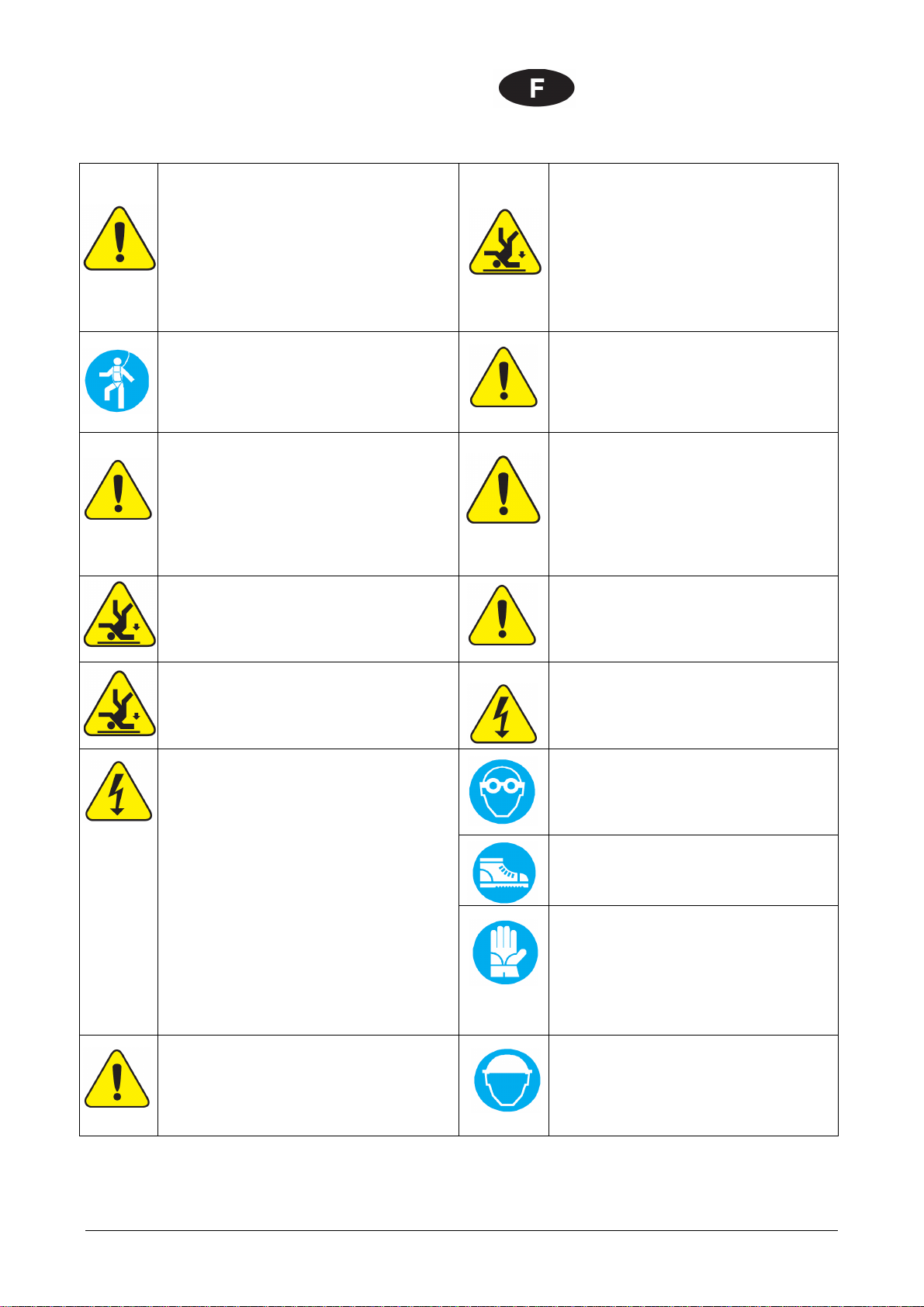
Installer le harnais de sécurité si possible au
dessus de l'utilisateur. Le harnais de sécurité doit
uniquement être fixé aux structures porteuses ou
points d'ancrage!
Au cas où les mesures de sécurité des personnes
ou de protection contre les chutes ne peuvent être
remplies, il est impératif d'utiliser des harnais de
sécurité.
Ne pas utiliser d'échelles endommagées, p. ex.
une échelle avec des échelons ou des barres
cassés ou échelles en métal tordues ou
défectueuses. Ne jamais réparer des barres,
limons ou échelons défectueux!
Utiliser uniquement des harnais de sécurité
autorisés et contrôlés par des organes de contrôle
(ceintures de maintien ou harnais antichute, longes
et sangles d'arrimage, cordons amortisseurs,
raccourcisseur de cordons).
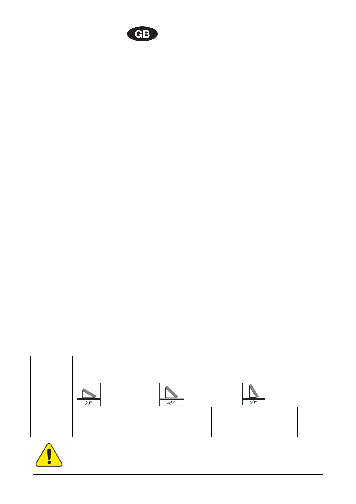
Poser l'échelle contre le mur de manière à ce
qu'elle ne puisse glisser. Respecter l'angle
d'inclinaison correct (68° - 75°). Sécuriser
l'échelle posée contre le mur de manière à ce
qu'elle ne puisse glisser, tomber ou s'enfoncer
dans le sol, p. ex. en renforçant les pieds
d'échelle, en adaptant les pieds au sol ou à l'aide
de dispositifs d'accrochage.
Si aucune protection antichute ou de rattrapage
n'est prévue et si aucun harnais de sécurité n'est
utilisé, il y a risque de chutes de grande hauteur et
donc de blessures graves voire mortelles!
Ne poser l'échelle que contre un point d'appui
solide. Sécuriser les échelles par des barrages
dans les zones de circulation de véhicules.
Lors de l'utilisation d'échelles, il y a risque de
chutes dangereuses si l'échelle s'enfonce dans le
sol, glisse ou tombe!
Ne jamais toucher les câbles électriques sous
tension: danger de mort.
Lors de l'utilisation de perceuses et d'un
maniement des capteurs à tubes sous vide
(danger d'implosion), porter des lunettes de
sécurité!
Lors du montage, porter des chaussures de
sécurité!
Ne réaliser des travaux à proximité de câbles
électriques sous tension où il y a risque de contact
que si:
- les câbles sont mis hors tension et sécurisés pour
la durée des travaux.
- les éléments sous tension sont recouverts ou
sécurisés.
- les distances de sécurité minimales sont
respectées.
Distance de tension:
1 m pour .....................une tension de 1 000 volts
3 m pour ....... une tension de 1 000 à 11 000 volts
4 m pour ......une tension de 11 000 à 22 000 volts
5 m pour ......une tension de 22 000 à 38 000 volts
> 5 m pour une tension inconnue
Lors du montage des capteurs solaires et d'un
maniement des capteurs à tubes (danger
d'implosion), porter des gants de travail
résistants aux coupures!
Le fabricant s'engage par la présente à reprendre
les produits portant le label de protection de
l'environnement et les matériaux utilisés et à
procéder à leur recyclage.
N'utiliser que le fluide caloporteur prescrit!
Lors du montage, porter un casque!
Instructions de sécurité

0DNO0009 Solar Plan 500V / 1000V - Installation-Utilisation 5/40
Les prescriptions, reglementations et directives suivantes doivent être observées pour le montage et le service :
- EN 12976 et EN 12977 : Raccordement d’installations thermiques, - NF P50-601-1 : DTU 65.12 : Réalisation des
installations de capteurs solaires plans, - Cahier du CSTB 1827 : Cahier des prescriptions Techniques communes aux
capteurs plans.
Généralités et consignes relatives au transport
Seuls les spécialistes en la matière sont autorisés à réaliser le montage. Toutes les instructions contenues dans le
présent guide s'adressent exclusivement aux spécialistes sus spécifiés. Utilisez toujours le matériel livré pour le
montage. Veuillez vous informer sur les normes et réglementations locales respectives en vigueur avant de procéder au
montage et à la mise en service de l'installation de capteurs solaires. Pour transporter le capteur solaire, il est
recommandé d'utiliser une grue de montage. Le capteur solaire doit être soulevé uniquement par les oreilles de levage
prémontées, jamais par les raccords. Évitez tout choc, torsion ou autre influence mécanique, prêtez une attention toute
particulière au verre solaire, à la face arrière du capteur solaire ainsi qu'aux raccords filetés du capteur.
Statique
Ne réalisez le montage que sur une surface de toit ou une sous construction suffisamment solides. Avant de procéder au
montage des capteurs solaires, la solidité statique de la toiture ou de la sous construction doit impérativement être
contrôlée sur site, éventuellement par un ingénieur B.T.P., en fonction des conditions locales et régionales. Pour se faire,
prêtez une attention toute particulière à la qualité de la sous construction pour assurer la solidité des raccords destinés à
fixer les dispositifs de montage des capteurs. Le contrôle de construction de l'ensemble du montage des capteurs
conformément aux réglements DTU P06-002 : ‘Règles NV65 – Règles définissant les effets de la neige et du vent sur les
construction et annexes’ et DTU P06-006 : ‘Règles N84 – Actions de la neige sur les constructions’ ou conformément
aux dispositions régionales en vigueur est indispensable dans les régions où il neige en abondance (remarque: 1 m³ de
neige poudreuse ~ 60 kg / 1 m³ neige mouillée ~ 200 kg) ou dans les régions dans lesquelles la vitesse du vent est
élevée (voir tableau " Réactions d'appui "). Il faut pour cela tenir compte des spécificités du lieu d'installation
(augmentation de la vitesse du vent dans certaines conditions, formation de tourbillons, etc.) qui peuvent entraîner une
charge plus importante. Les champs de capteurs sont à monter, en principe, de sorte que la neige éventuellement
retenue par les grilles à neige (ou par une situation particulière de montage) n'atteigne pas les capteurs. La distance par
rapport au faîtage/aux bords du toit doit être d'au moins 1 m.
Remarque: Le montage d'un champ de capteurs est une intervention dans un toit (existant); les
combles aménagés et habités ou les pentes de toit présentant une inclinaison inférieure à la normale (se
rapportant à la couverture) requièrent des mesures de construction supplémentaires afin de garantir une
sécurité optimale contre une intrusion d'eau liée à la pression du vent et à de la neige poudreuse. Pour
des champs de capteurs plus grands, il est recommandé dans la plupart des cas de monter les capteurs
solaires sur des supports de montage en profilés d'acier. Cette variante de fixation au moyen de blocs de
lest en béton et de suspentes permet un montage qui laisse la couverture du toit intacte. Les capteurs
solaires sont montés sur des blocs en béton. Nous recommandons d'utiliser des nattes inférieures en
caoutchouc pour renforcer le frottement statique entre le toit et les blocs de lest en béton ainsi que pour
éviter des endommagements de la couverture du toit. Si les dimensions des blocs de lest en béton sont
conformes au tableau ci-dessous, il n'est pas nécessaire de renforcer encore la fixation au moyen de
cordes en acier. Si le poids total (poids totaux des blocs de lest en béton et charge de neige maximale
possible) dépasse la portance statique de la sous construction, on pourra renforcer la fixation par des
blocs de lest en béton plus légers associés à des cordes en acier supplémentaires d'une section de 5 mm
(solidité minimale à la traction de 1 450 N/mm²).
Tableau: Dimensions des blocs de lest en béton en fonction de la charge du vent (non fourni)
Blocs de lest en béton (voir montage page 32)
Dimensions/poids pour chaque paire d’appui
Les données relatives au poids des blocs de lest en béton s'appliquent pour un coefficient de frottement de 0,6
(béton sur béton á l´état sec)
Vitesse du
vent [km/h]
L/B/H [m] kg L/B/H [m] kg L/B/H [m] kg
100
,40 x 0,30 x 0,17
295
2,40 x 0,30 x 0,21
365
,40 x 0,30 x 0,30
520
150
,40 x 0,30 x 0,46
795
2,40 x 0,30 x 0,48
830
,40 x 0,30 x 0,7
1245
Si l'on utilise des blocs de lest en béton dont le poids est inférieur aux indications requises dans le tableau ci-
dessus, il convient de les sécuriser au moyen de cordes en acier (5 mm / solidité minimale à la traction de 1 450
N/mm²)!
Supports version "High Load" (HL): 3kN/m de neige, 150 km/h de vent
Instructions de montage

0DNO0009 Solar Plan 500V / 1000V - Installation-Utilisation 6/40
Protection contre la foudre / liaison équipotentielle du bâtiment
Conformément à la norme actuelle relative à la protection contre la foudre, Annexe F de l’EN 12976-2:2000 :
‘Prescription relative à la protection contre la foudre’, le champ de capteurs ne peut être raccordé au
parafoudre du bâtiment. Une distance de sécurité d'1 m au minimum doit être respectée par rapport à
tout objet voisin envisageable. Pour les montages sur des sous constructions métalliques, il convient de
consulter des électriciens spécialisés agréés. Afin d'assurer l'équipotentialité du bâtiment, les tuyauteries
métalliques du circuit solaire ainsi que les boîtiers des capteurs ou les fixations doivent être raccordés au
rail de liaison équipotentielle principal par un électricien spécialisé agréé et conformément à la norme NF
C15-100 : ‘Installation électrique à basse tension – Complétée avec la mise à jour de juin 2005’ ou aux
normes nationales applicables.
Raccords
Les capteurs solaires, qui sont munis de quatre raccords filetés (G1 ¼" Mâle), sont à fixer les uns aux
autres ou à la tuyauterie avec des raccords à joints plats haute température. Vérifiez que les joints
plats ‘haute température’ sont bien serrés. Utilisez les compensateurs hydrauliques entre les capteurs
solaires afin de compenser la dilatation des tubes en cuivre résultant des variations de températures.
En utilisant les compensateurs de longueur, vous pouvez raccorder en série sur un même champ :
-8 capteurs solaires Solar Plan 500V de 5m² au maximum,
-4 capteurs solaires Solar Plan 1000V de 10m² au maximum.
Chaque champ de capteurs sera raccordé selon Tichelmann.
En serrant les raccords à l'aide d’une clef, ne dépassez pas un couple de serrage de 30 Nm pour ne pas
endommager la tuyauterie ou l'absorbeur.
Inclinaison des capteurs solaires – généralités
Les systèmes de fixation pour capteur solaire ont été conçus pour les types de montage présentant une
inclinaison de 30°, 45° et 60°, mais les capteurs solaires peuvent être également montés avec une
inclinaison de 5° minimum et de 75° maximum!
Protégez les raccords des capteurs et les ouvertures de purge contre les intrusions d'eau ainsi que contre
les salissures comme les entrées de poussières, etc.
Garantie
Les droits de garantie ne s'appliquent que si le fluide solaire d’origine du Groupe Atlantic est utilisé et que
l'entretien est effectué de manière conforme. Le recours à la garantie présuppose un montage réalisé par
des spécialistes en la matière dans le strict respect des instructions.
Montage des sondes
Le doigt de gant d'immersion de la sonde doit être montée à l'aller du circuit solaire, c'est-à-dire au
niveau du tube collecteur supérieur du dernier capteur solaire monté en série. Si plusieurs champs de
capteurs solaires sont réunis dans un circuit, le doigt de gant de la sonde de température départ capteur
devra être montée en sortie du circuit solaire, c'est-à-dire au niveau du tube collecteur supérieur du
dernier capteur solaire du champ le plus éloigné de la pompe de la station solaire.
Montage des purgeurs d’air
Installer un purgeur automatique d’air, adapté aux installations solaires, au point le plus haut de chaque
champ de capteurs. La fermeture de la vanne manuelle des purgeurs est obligatoire après la
purge complète de l’installation
Equilibrage des débits du fluide solaire
Une vanne d’équilibrage installée sur chaque champ de capteurs permet d’équilibrer les débits du fluide
solaire. Cela permet d’obtenir une bonne productivité solaire de l’installation et d’éviter les surchauffes.
Cette vanne d’équilibrage ne doit jamais être complètement fermée.
La vanne d'équilibrage du collecteur général sera placée sur la terrase afin de faciliter la mise au point de
l'équilibrage général de l'installation.
Instructions de montage

0DNO0009 Solar Plan 500V / 1000V - Installation-Utilisation 7/40
Raccordement des champs de capteurs
Pour l'installation des capteurs, il est recommandé d'employer des tubes cuivre avec raccords brasés en
cuivre également. Ne pas installer de vannes d’isolement sur le raccordement d’un capteur ou d’un
champ de capteur.
L'isolation de la tuyauterie extérieure doit être résistante aux températures, au rayonnement ultraviolet
et aux attaques aviaires.
N'employer que des joints et des composants Hautes températures spécifiques solaires.
Rinçage et remplissage
Pour des raisons de sécurité, veuillez effectuer le remplissage uniquement pendant les périodes de non
ensoleillement ou après avoir recouvert les capteurs d’une protection solaire. Pour bénéficier de
la garantie capteur, il est impératif d'utiliser du Tyfocor L à 45% (un mélange eau antigel
composé de 55 % d'eau et de 45 % d'antigel). L'installation solaire doit être remplie et mise en
service dans la semaine suivant son montage, car la montée en température des (champs de) capteurs
vides de fuide solaire, peut endommager les joints plats. Si toutefois cela n'est pas possible, il est
recommandé de remplacer les joints plats haute température avant la mise en service de l'installation
pour prévenir tout risque de fuite.
Attention:
Utilisez le fluide solaire composé de 45 % de Tyfocor L (propylène-1, glycol avec
inhibiteurs de corrosion) fourni par le Groupe ATLANTIC.
Remarque :
-45 % d’antigel Tyfocor L (55 %/d’eau) : Point de congélation= - 5°C / Point de solidification= -35°C
Il est possible que des capteurs une fois remplis ne puissent plus être entièrement vidés. Pour cette
raison, si le gel est un facteur à prendre en compte, veuillez ne remplir les capteurs qu'avec un mélange
eau antigel et ce, même pour effectuer les contrôles de pression et de fonctionnement. Le contrôle de
pression peut également être effectué avec de l'air comprimé ou un vaporisateur de détection des fuites
de gaz.
Pression de service
La pression de service maximale est de 10 bars.
Opérations de purge d’air
Il est nécessaire de purger l’installation de l’air qui s’y trouve:
- lors de la mise en service (après le remplissage)
- 4 semaines après la mise en service
- en cas de dysfonctionnement
Fermer les vannes des purgeurs d’air après la purge de l’installation
Avertissement:
Vapeur et fluide caloporteur brûlant ! Risque de brûlure
N'activez le purgeur d’air que lorsque la température du fluide caloporteur est de < 60° C.
Les capteurs ne doivent pas être chauds lors de la vidange de l'installation! Recouvrez les capteurs et
videz l'installation le matin de préférence.
Contrôle du fluide caloporteur
Il est nécessaire de procéder une fois par an à un contrôle du fluide caloporteur pour vérifier la protection
antigel et la valeur pH.
- Vérifiez le point de gel au moyen d'un réfractomètre; remplacez l'antigel ou rajoutez de l'antigel
le cas échéant! Valeur de référence approx. - 5° C.
- Vérifiez la valeur pH au moyen d'un indicateur de pH (valeur de référence approx. pH 7,5) : si la
valeur descend en dessous de la valeur limite de < pH 7, veuillez changer le fluide caloporteur.
Maintenance du capteur solaire
Le capteur solaire ou le champ de capteurs solaires doit être soumis à un contrôle optique annuel relatif à
des dommages divers, à l'étanchéité et à des encrassements. Si nécessaire, il est possible de changer la
vitre par module de ,5m².
Vous trouverez d'autres recommandations concernant le fonctionnement et la maintenance dans les
documents et les instructions relatives à la mise en service et à la maintenance :
-Rapport de Mise en Service des installations d’ECS solaire collective,
-Cahier de Maintenance des installations d’ECS solaire collective.
Recommandations d’emploi

0DNO0009 Solar Plan 500V / 1000V - Installation-Utilisation 8/40
Safety precautions: Before commencing mounting
work on roofs, it must be ensured in all cases that
the non-personal fall protection and fall-arrest
systems required by DIN 18338 (Roof Covering
and Roof Sealing Works) and DIN 18451
(Scaffolding Works) are in place. See also Builders'
Protection Ordinance
[Bauarbeiterschutzverordnung], Federal Law
Gazette 340/1994, paragraphs 7-10! Other country-
specific regulations must be observed!
Safety harnesses should be fixed above the
users whenever possible. Safety harnesses
should only be fastened to sufficiently load-
bearing structures or fixing points!
If non-personal fall protection or fall-arrest systems
cannot be installed for technical reasons, all
personnel must be secured by means of suitable
safety harnesses!
Never use damaged ladders (e.g., wooden
ladders with split runners or rungs, or bent or
buckled metal ladders). Never try to repair broken
runners, rungs or steps on wooden ladders!
Only use safety harnesses (safety belts, lanyards
and straps, shock absorbers, fall arresters) that
were tested and certified by authorized testing
bodies.
Ensure that ladders are put up safely. Observe
the correct leaning angle (68° - 75°). Prevent
ladders from sliding, falling over or sinking into
the ground (e.g. using wider feet, feet suited to
the ground or hooking devices).
If non-personal fall protection or fall-arrest systems
are not provided, working without the use of
suitable safety harnesses may lead to falls from
heights and therefore cause serious or lethal
injuries!
Only lean ladders against secure points. Secure
ladders in traffic areas by suitable cordoning.
Ladders not properly secured against sinking in,
sliding or falling over may lead to dangerous falls!
Contact with live electric overhead cables can be
lethal.
Wear protective goggles when drilling and
handling evacuated tube collectors (danger of
implosion)!
Wear safety shoes when carrying out installation
work!
Whenever you are near live overhead electric
cables where contact is possible, only work if:
- it is ensured that they are voltage-free and this is
secured for the duration of work.
- the live parts are secured by covering them or
cordoning them off.
-the prescribed safety distances are maintained.
Voltage radius:
1m with .......................voltages up to 1000V
3m with ........voltages from 1000V to 11000V
4m with ......voltages from 11000V to 22000V
5m with ......voltages from 22000V to 38000V
5m in case of unknown voltages
Wear cut-proof safety gloves when mounting
collectors and handling evacuated tube collectors
(danger of implosion)!
The manufacturer hereby guarantees to take back
products identified with an eco-label and to recycle
the materials used.
Only the heat transfer medium specified may be
used!
Wear a helmet when carrying out installation
work!
Safety information

0DNO0009 Solar Plan 500V / 1000V - Installation-Utilisation 9/40
The following regulations and directives must be observed for the assembly and the service :
- EN 12976 et EN 12977 : Thermal solar systems and compoments, - NF P50-601-1 : DTU 65.12 : Réalisation des
installations de capteurs solaires plans, - Cahier du CSTB 1827 : Cahier des prescriptions Techniques communes aux
capteurs plans.
General and transport instructions
Installation must only be carried out by qualified personnel. The entire information in these instructions is
intended exclusively for such qualified personnel. Only the supplied material should be used for the
installation. Prior to starting installation and operation of the solar collector system, please inform
yourself about the applicable local standards and regulations. We recommend using an assembly crane
for transporting the collector. The collector must only be lifted via the pre-mounted lifting rings and must
not be lifted at the connections. Avoid impacts and mechanical influences on the collector, in particular on
the solar glass, the collector rear panel and pipe connections.
Statics
The collectors may only be mounted on sufficiently load-bearing roof surfaces and substructures. It is
imperative that the static load bearing capacity of the roof or substructure is checked in terms of local
and regional conditions prior to installation of the collectors by the customer, if necessary through the
involvement of a structural engineer. Particular attention should be paid to the quality of the substructure
in terms of the stability of the screw connections necessary for fastening the collectors. The checking of
the entire collector structure by the customer as per DIN 1055 part 4 and 5 or as per the applicable
country-specific regulations is particularly important in areas with heavy snowfall (note: 1m³ powder
snow ~ 60kg / 1m³ wet snow ~ 00kg) or in areas exposed to high wind speeds (see table "Reactions to
requirements"). The assessment should also take into account any particular circumstances at the place
of installation (foehn wind, air jets or eddy formation etc.) which can lead to increased loads. As a rule,
collector arrays must be installed such that any possible collection of snow is prevented from reaching the
collectors by snow barriers (or through special forms of installation). The distance to roof ridges/edges
must be at least 1m.
Note: The installation of a collector array is an intervention into a (existing) roof; above all, converted
and inhabited loft spaces or roofs with less than the minimum slope (with regards to the covering)
require additional measures by the customer, e.g. sarking membranes, as protection against the
penetration of water through wind pressure and driving snow. With larger collector arrays, we
recommend installing the collectors on a special supporting structure made of steel channels.
Alternatively, it is possible to install the collectors without perforating the roof membrane by using
concrete ballast with guys. The collectors are mounted on concrete blocks. Rubber mats should be used if
necessary to protect the roof membrane against damage and to increase the friction between the roof
and the ballast blocks. If the dimensions of the concrete ballast blocks are adhered to as per the table
below, no additional securing through steel cables is required. If the total weight (total weight of the
concrete ballast blocks and maximum possible snow load) exceeds the static load bearing capacity of the
substructure, a combination of lighter concrete ballast blocks plus additional 5 mm steel cables (minimum
tensile strength 1450N/mm²) can be used for securing.
Table: Concrete ballast dimensions dependent on wind load
Betonballäste
Concrete ballasts
Dimensions/weight per support pair
The weight specifications of the ballast blocks apply under the assumption of a friction coefficient of 0.6
(concrete on concrete in dry condition)
Wind load
[km/h] L/B/H [m] kg L/B/H [m] kg L/B/H [m] kg
100
,40 x 0,30 x 0,17
295
2,40 x 0,30 x 0,21
365
,40 x 0,30 x 0,30
520
150
,40 x 0,30 x 0,46
795
2,40 x 0,30 x 0,48
830
,40 x 0,30 x 0,7
1245
If concrete ballast is used whose weight is below that given in the table above, additional securing with steel
cables (5mm / min. tensile strength 1450N/mm²) are required!
Mountingset "High Load" (HL): 3kN/m² snow, 150km/h wind
Assembly instructions

0DNO0009 Solar Plan 500V / 1000V - Installation-Utilisation 10/40
Lightning protection / equipotential bonding of the building
In accordance with the lightning protection standard ÖVE/ÖNORM EN 6 305 Part 1-4 the collector array
cannot be connected to the building's lightning protection. A safety distance of at least 1 m must be
maintained from any possible adjacent conducting object. For installations on metal substructures at the
installation site, generally qualified electricians must be consulted. To carry out a building potential
equalisation, the metal tubes of the solar circuit and all collector cases or fastenings must be connected
to the main potential equalisation bus by a qualified electrician in accordance with ÖVE/ÖNORM E 8001-1
or the country-specific standards.
Connections
The collectors are equipped with four screw connections (G1 ¼" male thread) and must be connected
with high temperature flat sealing to each other or to the system connection pipes. Ensure correct
placement of the high temperature flat gaskets. Length compensators must be used as connection
elements between the collectors in order to compensate the length expansion of the copper pipes during
temperature fluctuations. Provided that the length compensators are used, the collectors can be
connected in series as follows:
-8 collectors Solar Plan 500V de 5m² maximum,
-4 collectors Solar Plan 1000V de 10m² maximum.
Each field of collectors will be connected according to Tichelmann.
When tightening the connections with the spanner, a torque of 30Nm should not be exceeded so as to
prevent damage to the manifold or absorber.
Collector angle / General notes
The collector fixing systems are designed to be assembled at 30°, 45° and 60°. The collectors are
suitable for a minimum angle of 5° and a maximum angle of 75°!
The collector connections and the ventilation openings must be protected against the penetration of water
as well as against contamination through dust etc.
Warranty
Warranty claims can only be made if the Groupe Atlantic's own antifreeze has been used and
maintenance has been carried out correctly. Installation by qualified personnel with absolute adherence
to the instructions is a prerequisite for the justification of claims.
Installing the sensor
The sensor immersion sleeve must be installed on the solar supply, i.e. on the upper manifold of the last
collector connected in the series. If there are several series of collectors which are combined in a circuit,
the sensor immersion sleeve must be installed on the solar supply, i.e. on the upper manifold of the last
collector connected in the series farthest away from the pump.
Installation of air vent
Install an automatic air vent, adapted to the solar installations, the point highest of each field of collectors.
The closing of the manual valve of the air vent is obligatory after the complete bleeding of the
installation.
Balancing the flows of the solar fluid
A valve of balancing installed on each field of collectors makes possible to balance the flows of the solar fluid. That
makes it possible to obtain a good solar productivity of the solar system and to avoid overheatings. This valve of
balancing should never be completely closed.
The valve of balancing of the general collector will be placed on the flat roof in order to realize easily the
development of the general balancing of solar system.
Assembly instructions

0DNO0009 Solar Plan 500V / 1000V - Installation-Utilisation 11/40
Connection of the fields of collectors
For the installation of the collectors, it is recommended to use coppers pipe with connections brazed out of copper. Not to
install isolating valves on the connection of a sensor or a field of sensor.
Insulation of external piping must be resistant to the temperatures, the ultraviolet radiation and the avian attacks.
Use only gaskets and components for high temperatures solar specific.
Flushing and filling
For safety reasons, you should only fill the collectors when there is no direct irradiation from the sun (or
cover the collectors). Pour bénéficier de la garantie capteur, il est impératif d'utiliser du Tyfocor
L à 45% (55% water and 45 % antifreeze). The solar thermal system should be filled and commissioned
within one week of installation, because heat build-up in the collector (array) can damage the flat gaskets
in empty systems. If this is not possible, the haute temperature flat gaskets should be replaced before
commissioning to prevent leakage.
Attention:
Use the solar fluid made up of 45% of Tyfocor L (propylene-1,2 glycol with corrosion inhibitors)
provided by Groupe ATLANTIC!
Note: 45 % of antifreeze Tyfocor L (55 %/water) – Freezing point : - 5° C/ solidification point : -35° C
It may not be possible to completely empty collectors once they have been filled. For this reason,
collectors exposed to frost should only be filled with a water/antifreeze mixture, also for pressure and
function tests. Alternatively, the pressure test can also be carried out using compressed air and leak
detection spray.
Operating pressure
The maximum operating pressure is 10 bar.
Operating bleeding
The system must be bled:
- when commissioning the system (after filling the collectors)
- 4 weeks after commissioning
- when necessary, e.g. if there are malfunctions
Close the valves of the automatic air vent after the feeding of the installation
Warning:
Risk of scalding due to steam and hot heat transfer fluid!
Only operate the bleeding valve if the temperature of the heat transfer fluid is < 60°C .
When bleeding the system, the collectors must not be hot! Cover the collectors and, if possible, bleed the
system in the morning.
Check heat transfer fluid
The heat transfer fluid must be checked every two years with regard to its antifreeze and pH value.
- Check antifreeze using antifreeze tester and replace or refill if necessary! Target value is ca. - 5°
C.
- Check pH value with a pH indicator rod (target value approx. pH 7.5): If the limit pH value is less
than pH 7, replace the heat transfer fluid.
Maintenance of the collector
The collector or the collector array must be inspected visually, once a year, for any damage, leaks and
contamination.
If necessary, it is possible to change the glass by module of 2,5m ².
Additional recommendations on operation and maintenance can be found in the supplier's general
documentation and instructions on commissioning and maintenance:
-
Report of commissionning of the installations of solar systems
,
-
Book of maintenance of solar systems
.
Operating tips

0DNO0009 Solar Plan 500V / 1000V - Installation-Utilisation 12/40
Bei Dachmontagen vorschriftsmäßige
personenunabhängige Absturzsicherungen oder
Auffangeinrichtungen nach DIN 18338
Dachdeckungs- u. Dachdichtungsarbeiten und nach
DIN 18451 Gerüstarbeiten mit Sicherheitsnetz
unbedingt vor Arbeitsbeginn aufbauen!
Bauarbeiterschutz-Verordnung BGBL 340/1994 §7-
10! Sonstige, länderspezifische Vorschriften sind
unbedingt einzuhalten!
Sicherheitsgeschirr möglichst oberhalb des
Benutzers anschlagen. Sicherheitsgeschirr nur an
tragfähigen Bauteilen bzw. Anschlagpunkten
befestigen!
Falls personenunabhängige Absturzsicherungen
oder Auffangvorrichtungen aus arbeitstechnischen
Gründen nicht vorhanden sind, sind
icherheitsgeschirre zu verwenden!
Schadhafte Leitern nicht benutzen, z.B.
angebrochene Holme und Sprossen von
Holzleitern, verbogene und angeknickte
Metalleitern. Angebrochene Holme, Wangen und
Sprossen von Holzleitern nicht flicken!
Nur von autorisierten Prüfstellen gekennzeichnete
und geprüfte Sicherheitsgeschirre (Halte- oder
Auffanggurte, Verbindungsseile/bänder,
Falldämpfer, Seilkürzer) verwenden.
Anlegeleiter sicher aufstellen. Richtigen
Aufstellungswinkel beachten (68 ° - 75 °).
Anlegeleitern gegen Ausgleiten, Umfallen,
Abrutschen und Einsinken sichern, z.B. durch
Fußverbreiterungen, dem Untergrund angepasste
Leiterfüße, Einhängevorrichtungen.
Falls keine personenunabhängige
Absturzsicherungen oder Auffangvorrichtungen
vorhanden sind, kann es ohne Benutzung von
Sicherheitsgeschirren zu Abstürzen aus großen
Höhen und damit zu schweren oder tödlichen
Verletzungen kommen!
Leitern nur an sichere Stützpunkte anlehnen.
Leitern im Verkehrsbereich durch Absperrungen
sichern.
Bei Verwendung von Anlegeleitern kann es zu
gefährlichen Stürzen kommen, wenn die Leiter
einsinkt, wegrutscht oder umfällt!
Das Berühren spannungsführender, elektrischer
Freileitungen kann tödliche Folgen haben.
Bei Bohrarbeiten und beim Hantieren mit
Vakuum-Röhrenkollektoren (Implosionsgefahr)
Schutzbrille tragen!
Bei Montage Sicherheitsschuhe tragen!
In der Nähe spannungsführender, elektrischer
Freileitungen, bei denen ein Berühren möglich ist,
nur arbeiten, wenn
- deren spannungsfreier Zustand hergestellt und
für die Dauer der Arbeit sichergestellt ist.
- die spannungsführenden Teile durch Abdecken
oder Anschranken geschützt sind.
- die Sicherheitsabstände nicht unterschritten
werden.
Spannungsradius:
1 m bei .........................1000 Volt Spannung
3 m bei ..........1000 bis 11000 Volt Spannung
4 m bei ........11000 bis 000 Volt Spannung
5 m bei ........ 000 bis 38000 Volt Spannung
> 5 m bei unbekannter Spannungsgröße
Bei der Kollektormontage und beim Hantieren mit
Vakuum-Röhrenkollektoren (Implosionsgefahr)
schnittsichere Arbeitshandschuhe tragen!
Der Hersteller verpflichtet sich hiermit, die mit dem
Umweltzeichen gekennzeichneten Produkte und die
darin eingesetzten Materialien zurückzunehmen
und einer Wiederverwertung zuzuführen. Es darf
nur das vorgeschriebene Wärmeträgermedium
eingesetzt werden!
Bei Montage Helm tragen!
Sicherheitshinweise

0DNO0009 Solar Plan 500V / 1000V - Installation-Utilisation 13/40
Allgemeine - und Transporthinweise
Die Montage darf nur von fachkundigen Personen vorgenommen werden. Ausschließlich an solche
fachkundigen Personen richten sich sämtliche Ausführungen dieser Anleitung. Grundsätzlich ist zur
Montage das mitgelieferte Materialzu verwenden. Informieren Sie sich vor der Montage und dem Betrieb
der Sonnenkollektoranlage über die jeweilsgültigen örtlichen Normen und Vorschriften. Zum Transport
des Kollektors empfiehlt sich die Verwendung eines Montagekrans. Der Kollektor ist nur an den
vormontierten Kranösen hochzuheben und darf nicht an den Anschlüssenhochgehoben werden.
Vermeiden Sie Stöße und mechanische Einflüsse auf den Kollektor, insbesondere auf Solarglas,
Kollektorrückwand und Rohranschlüsse.
Statik
Die Montage darf nur auf ausreichend tragfähigen Dachflächen bzw. Unterkonstruktionen erfolgen. Die
statische Tragfähigkeit des Daches bzw. der Unterkonstruktion ist vor der Montage der Kollektoren
bauseits, allenfalls durch Beiziehung eines Statikers auf örtliche und regionale Gegebenheiten unbedingt
zu prüfen. Dabei ist besonderes Augenmerk auf die Güte des Unterbaus bezüglich der Haltbarkeit von
Schraubverbindungen zur Befestigung von Kollektormontagevorrichtungen zu legen. Die bauseitige
Überprüfung des gesamten Kollektoraufbaues gemäß DIN 1055 Teil 4 und 5 bzw. gemäß den
länderspezifisch geltenden Vorschriften ist besonders in schneereichen Gebieten (Hinweis: 1 m³
Pulverschnee ~ 60 kg / 1 m³ Nassschnee ~ 00 kg) bzw. in Gebieten mit hohen Windgeschwindigkeiten
erforderlich (siehe Tabelle „Auflagereaktionen“). Dabei ist auch auf alle Besonderheiten des
Aufstellungsortes (Föhn, Düseneffekte, Wirbelbildung, etc.) einzugehen, welche zu erhöhter Belastung
führen können. Grundsätzlich sind Kollektorfelder so zu montieren, dass ev. möglicher Schneerückstau
durch Schneefanggitter (oder durch besondere Aufstellungssituationen) die Kollektoren nicht erreicht. Der
Abstand zu Dachfirsten/-rändern muss zumindest 1 m betragen.
Hinweis: Die Montage eines Kollektorfeldes ist ein Eingriff in ein (bestehendes) Dach, besonders
ausgebaute und bewohnte Dachgeschosse bzw. unterschrittene Mindestdachneigungen erfordern
(bezogen auf die Eindeckung) – als Sicherheit gegen das Eindringen von Wasser durch Winddruck und
Flugschnee zusätzliche, bauseitige Maßnahmen wie z. B. Unterspannbahnen. Für größere Kollektorfelder
wird empfohlen, die Kollektoren auf eine eigene Tragekonstruktion aus Stahlprofilen zu montieren. Die
Befestigungsvariante mittels Betonballastblöcken und Seilverspannungen ermöglicht eine Montage ohne
Durchdringung der Dachhaut. Die Kollektoren werden auf Betonblöcke montiert. Um die Haftreibung
zwischen Dach und Betonballastblöcken zu erhöhen sowie um Beschädigungen der Dachhaut zu
vermeiden, sind gegebenenfalls Gummiunterlagsmatten zu verwenden. Werden die Dimensionen der
Betonballastblöcke entsprechend der unten angeführten Tabelle eingehalten, ist keine zusätzliche
Absicherung mittels Stahlseilen notwendig. Falls das Gesamtgewicht (Gesamtgewichte der
Betonballastblöcke und maximal mögliche Schneelast) die statische Tragbarkeit der Unterkonstruktion
überschreiten, so kann eine Kombination aus leichteren Betonballastblöcken plus zusätzlicher 5 mm
starken Stahlseilen (Mindestzugfestigkeit 1450 N/mm²) zur Sicherung verwendet werden.
Tabelle: Betonballastdimensionen in Abhängigkeit der Windlast
Betonballäste
Dimensionen/Gewichte je Stützenpaar
Die Gewichtsangaben der Ballastblöcke gelten unter der Annahme eines Reibungskoeffizienten von 0,6
(Beton auf Beton im trockenen Zustand)
Windlast
[km/h] L/B/H [m] kg L/B/H [m] kg L/B/H [m] kg
100
,40 x 0,30 x 0,17
295
2,40 x 0,30 x 0,21
365
,40 x 0,30 x 0,30
520
150
,40 x 0,30 x 0,46
795
2,40 x 0,30 x 0,48
830
,40 x 0,30 x 0,7
1245
Werden Betonballäste verwendet deren Gewicht unter den in obiger Tabelle geforderten
Angaben liegen, ist eine Absicherung mit Stahlseilen (5 mm / Mindestzugfestigkeit 1450 N/mm²) erforderlich!
Befestigungsausführung „High Load“ (HL): 3 kN/m² Schnee, 150 km/h Wind
Montagehinweise

0DNO0009 Solar Plan 500V / 1000V - Installation-Utilisation 14/40
Die folgenden Vorschriften, Bestimmungen und Richtlinen müssen bei der Montage und dem Betrieb
eingehalten werden:
- EN 12976 und EN 1277 : Anschluss thermischer Installationen, - NF P50-601-1 : DTU 65.12 : Realisierung von flachen
Sonnenkollektorinstallationen, - Heft des CSTB 1827 : Heft mit den der flachen Sonnenkollektoren gemeinsamen
technischen Vorschriften.
Blitzschutz / Gebäudepotentialausgleich
Gemäß der aktuellen Blitzschutznorm ÖVE/ÖNORM EN 6 305 Teil 1-4 darf das Kollektorfeld nicht an den
Gebäudeblitzschutz angeschlossen werden. Ein Sicherheitsabstand von mindestens 1 m zu einem
möglichem benachbartem, leitendem Objekt ist einzuhalten. Bei Montagen auf bauseitigen
Unterkonstruktionen aus Metall sind generell befugte Elektrofachkräfte zu konsultieren. Um einen
Gebäudepotentialausgleich durchzuführen, müssen die metallischen Rohrleiter des Solarkreises sowie alle
Kollektorgehäuse bzw. Befestigungen gemäß ÖVE/ÖNORM E 8001-1 bzw. Den länderspezifischen Normen
mit der Hauptpotentialausgleichsschiene durch eine befugte Elektrofachkraft verbunden werden.
Anschlüsse
(Schraubverbindungen)
Die Kollektoren sind mit vier verschraubbaren Anschlüssen (G1 ¼" Male) ausgestattet und untereinander
bzw. mit der System-Anschlussverrohrung flachdichtend zu verbinden. Auf korrekten Sitz der
Flachdichtungen ist zu achten. Als Verbindungselemente zwischen den Kollektoren sind
Längenkompensatoren zu verwenden, um die Längenausdehnungen der Kupferrohre bei
Temperaturschwankungen zu kompensieren.
Indem Sie Längenkompensatoren verwenden, können Sie auf demselben Feld in Reihe montieren:
-8 flache Sonnenkollektoren 500V mit einer maximalen Größe von 5m²,
-4 flache Sonnenkollektoren 1000V mit einer maximalen Größe von 10m².
Jedes Kaptorenfeld wird gemäß Tichelmann angeschlossen.
Beim Anziehen der Anschlüsse mit dem Schraubenschlüssel sollte ein Drehmoment von 30 Nm nicht
überschritten werden, damit die Sammelleitung bzw. der Absorber nicht beschädigt wird.
Kollektorneigung – Allgemeines
Die Kollektorbefestigungssysteme sind für die Montagevarianten 30 °, 45 ° und 60 ° ausgelegt. Die
Kollektoren sind für eine Neigung von minimal 5 ° und maximal 75 ° geeignet!
Die Kollektoranschlüsse und die Be-/ Entlüftungsöffnungen sind vor Wassereintritt sowie vor
Verschmutzungen wie Staubeintrag, etc. zu schützen.
Gewährleistung
Gewährleistungsanspruch nur in Verbindung mit Original-Frostschutz des Lieferanten und
ordnungsgemäß durchgeführter Wartung. Einbau durch fachkundige Personen in ausnahmsloser
Befolgung der Montageanleitung zur Anspruchsbegründung vorausgesetzt.
Fühlermontage
Die Fühlertauchhülse ist am Solar Vorlauf, d.h. am oberen Sammelrohr beim letzten in der Reihe
geschalteten Kollektor zu montieren. Bei mehreren Kollektorreihen, die in einem Kreislauf
zusammengefasst sind, ist die Fühlertauchhülse am Solar Vorlauf, d.h. am oberen Sammelrohr beim
letzten, in der von der Pumpe am weitest entferntesten Reihe geschalteten, Kollektor zu montieren.
Entlüftungshahn
Ein an Solarinstallationen angepasster automatischer Entlüftungshahn ist an dem höchsten Punkt eines
jeden Kaptorenfeldes zu installieren. Das Schließen des manuellen Ventils der Entlüftungen ist
nach dem vollständigen Entlüften der Installation zwingend erforderlich
Ausgleich der Durchsätze der Wärmeträgerflüssigkeit
Ein Ausgleichventil, das auf jedem Kollektorenfeld angebracht ist, erlaubt es, die Durchsätze der
Wärmeträgerflüssigkeit auszugleichen. Dies erlaubt, eine gute Solar-Produktivität der Installation zu
erhalten. Dieses Ausgleichventil darf nie vollständig geschlossen werden.
Das Ausgleichventil des Generalkollektors wird auf der Terrasse angebracht, um die Justierung des
allgemeinen Ausgleichs der Installierung zu erleichtern.
Montagehinweise

0DNO0009 Solar Plan 500V / 1000V - Installation-Utilisation 15/40
Anschluss der Kaptorenfelder
Für die Installation der Kaptoren empfiehlt es sich, Kupferrohe mit gelöteten Anschlüssen zu verwenden,
die ebenfalls aus Kupfer sind. Es dürfen keine Isolierungsventile auf dem Anschluss eines Kaptoren oder
eines Kaptorenfeldes installiert werden.
Die Isolierung der äußeren Rohrleitungen muss temperaturresistent sein, sowie den UV-Strahlen und den
Vogelangriffen widerstehen.
Es sind nur spezifische Solar-Hochtemperaturdichtungen und -komponente zu verwenden.
Spülung und Befüllung
Aus Sicherheitsgründen ist die Füllung ausschließlich während Zeiten ohne Sonneneinstrahlung oder mit
abgedeckten Kollektoren durchzuführen. Pour bénéficier de la garantie capteur, il est impératif
d'utiliser du Tyfocor L à 45% -igem Frostschutzmittel Wasser-Gemisch notwendig.
Die Solaranlage ist innerhalb einer Woche ab Montage zu befüllen und in Betrieb zu nehmen, da es durch
die Wärmeentwicklung im Kollektor(feld) bei leeren Anlagen zu Beschädigung der Flachdichtungen
kommen kann. Ist dies nicht möglich, sollten die Flachdichtungen vor der Inbetriebnahme erneuert
werden, um Undichtheiten vorzubeugen.
Achtung:
Benutzen Sie die Wärmeträgerflüssigkeit, die zu 45% aus Tyfocor L besteht (Propylen-1,
Glycol mit Hemmstoffen) von Groupe Atlantic.
Hinweis: 45 % Tyfocor L -Anteil (55%/H 0) - Gefrierpunkt: - 5 ° C / Stockpunkt: - 35 ° C
Es ist möglich, dass einmal befüllte Kollektoren nicht mehr vollständig entleert werden können. Deshalb
dürfen Kollektoren bei Frostgefahr auch für Druckproben und Funktionstests nur mit
Wasser/Frostschutzgemisch befüllt werden. Alternativ kann die Druckprobe mit Druckluft und
Lecksuchspray durchgeführt werden.
Betriebsdruck
Der maximale Betriebsdruck beträgt 10 bar.
Entlüften
Eine Entlüftung muss durchgeführt werden:
- bei Inbetriebnahme (nach dem Befüllen),
- 4 Wochen nach der Inbetriebnahme,
- bei Bedarf, z.B. Störungen.
Die Schieber der Entlüftungshahn nach dem vollständigen Entlüften der Installation schließen.
Warnung:
Verbrühungsgefahr durch Dampf bzw heiße Wärmeträgerflüssigkeit!
Entlüftungsventil nur betätigen, wenn die Temperatur der Wärmeträgerflüssigkeit < 60 °C ist.
Beim Entleeren der Anlage dürfen die Kollektoren nicht heiß sein! Kollektoren abdecken und Anlage
möglichst morgens entleeren.
Wärmeträgerflüssigkeit prüfen
Die Wärmeträgerflüssigkeit muss alle Jahre auf Frostschutz und pH-Wert überprüft werden.
- Frostschutz mittels Frostschutzprüfer prüfen und gegebenenfalls tauschen bzw. nachfüllen!
Sollwert ca. - 5 ° C bis - 30 ° C bzw. je nach klimatischen Gegebenheiten.
- pH-Wert mit einem pH-Indikatorstäbchen prüfen (Sollwert ca. pH 7,5): Bei Unterschreiten des
Grenz-pH-Wertes von ! pH 7 die Wärmeträgerflüssigkeit tauschen.
Wartung des Kollektors
Der Kollektor bzw. das Kollektorfeld ist jährlich durch eine optische Kontrolle auf div. Schäden, Dichtheit
und Verschmutzungen zu prüfen. Falls erforderlich, ist es möglich, die Scheibe durch Module in einer
Größe von ,5m². Korrosion), die von der Gruppe ATLANTIC geliefert werden, auszutauschen. Weitere
Empfehlungen zu Betrieb und Wartung finden Sie in den allgemeinen Inbetriebnahme- und
Wartungsunterlagen:
-Bericht über die Inbetriebnahme der kollektiven Warmwasser Solar-Installationen,
-Wartungsheft der kollektiven Warmwasser Solar-Installationen.
Betriebsempfehlungen

0DNO0009 Solar Plan 500V / 1000V - Installation-Utilisation 16/40
In caso di montaggio sul tetto costruire
necessariamente prima dell’inizio dei lavori
dispositivi anticaduta oppure di salvataggio a
norma generici, come previsto dalla DIN 18338
Lavori di copertura e di tenuta del tetto e dalla DIN
18451 Lavori su impalcature con rete di sicurezza!
Ordinamento di sicurezza del personale edile
BGBL 340/1994 §7-10! Rispettare assolutamente
le norme specifiche del relativo paese!
Agganciare l’imbracatura di sicurezza
possibilmente al di sopra dell’utente. Fissare
l’imbracatura di sicurezza soltanto ad elementi o
a punti di aggancio saldi!
Qualora per motivi tecnici di lavoro non esistessero
dispositivi anticaduta e di salvataggio generici,
vanno adottate imbracature di sicurezza!
Non utilizzare scale danneggiate, ad es. scale in
legno con corrimano e pioli spezzati, oppure
scale di metallo piegate e deformate. Non
rappezzare corrimano, staggio e pioli spezzati di
scale di legno!
Adottare soltanto imbracature di sicurezza
controllate e dotate di marchio rilasciato da enti
ufficiali di controllo (cinture di sostegno e di
salvataggio, funi/fasce di sicurezza, cinture
smorzacaduta, accorciafuni).
Posizionare le scale da appoggio in modo sicuro.
Rispettare il giusto angolo di appoggio (68 °- 75
°). Assicurare le scale da appoggio dal pericolo di
scivolamento, di caduta e di affossamento, ad es.
ingrandendone i piedi, adottando piedi idonei alla
superficie d’appoggio, usando dispositivi di
aggancio.
Qualora non esistano dispositivi anticaduta e di
salvataggio, la mancata adozione di imbracature di
sicurezza può essere causa di caduta da grandi
altezze con conseguenti lesioni gravi o mortali!
Appoggiare le scale solo a punti di sostegno
sicuri. In zone di traffico assicurare le scale
mediante sbarramenti.
In caso di impiego di scale da appoggio possono
verificarsi cadute pericolose qualora la scala si
affossi, scivoli, o cada.
Il contatto con linee elettriche scoperte in
tensione, può avere conseguenze mortali.
Durante i lavori di perforazione e maneggiando i
collettori a tubo sottovuoto portare gli occhiali
protettivi (pericolo di implosione)!
Durante il montaggio portare le scarpe di
sicurezza!
È consentito lavorare nei pressi di linee elettriche
scoperte in tensione, che possono essere anche
toccate, solo se
- manca la tensione e questa condizione è garantita
per tutta la durata dei lavori.
- le parti di conduzione della tensione sono protette
mediante copertura oppure sbarramento.
- vengono rispettate le distanze di sicurezza.
Raggio di te
1 m........................ con tensione di 1000 Volt
3 m...........con tensione da 1000 a 11000 Volt
4 m......... con tensione da 11000 a 22000 Volt
5 m......... con tensione da 22000 a 38000 Volt
> 5 m con tensione sconosciuta
Durante il montaggio dei collettori e
maneggiando i collettori a tubo sottovuoto portare
guanti di sicurezza antitaglio (pericolo di
implosione)!
Con la presente il produttore si impegna a ritirare i
prodotti contrassegnati con il marchio ecologico e i
materiali che essi contengono e a provvedere al
riciclaggio.
Usare esclusivamente il fluido termovettore
prescritto!
Durante il montaggio portare il casco di
sicurezza!
Avvertenze per la sicurezza

0DNO0009 Solar Plan 500V / 1000V - Installation-Utilisation 17/40
Informazioni generali e per il trasporto
L'installazione deve essere eseguita solo da personale competente. Tutte le versioni del presente
documento sono destinate unicamente a personale qualificato. Di norma si raccomanda di utilizzare per il
montaggio il materiale d'installazione fornito. Prima del montaggio e della messa in esercizio è opportuno
informarsi sulle norme e disposizioni del luogo in cui è situato l'impianto a collettori solari. Per il trasporto
del collettore si consiglia l'impiego di una gru di montaggio. Il collettore deve essere sollevato solo
mediante gli occhielli di sollevamento premontati e non deve essere sollevato servendosi degli attacchi.
Evitate che il collettore subisca urti e azioni meccaniche, proteggete soprattutto il vetro solare, la parete
posteriore del collettore e gli attacchi per i tubi.
Statica
Il montaggio deve avvenire soltanto su superfici di tetti o sottostrutture sufficientemente robusti. La
capacità statica del tetto o della sottostruttura deve essere assolutamente verificata sul posto prima di
procedere al montaggio dei collettori; rivolgersi eventualmente ad un ingegnere strutturista che conosca
le caratteristiche locali e regionali del terreno. In questa operazione deve essere attentamente valutata
l'idoneità del legno dell'intelaiatura riguardo alla tenuta dei collegamenti a vite predisposti per il fissaggio
dei collettori. La verifica realizzata dal costruttore dell'intera intelaiatura del collettore in base alle norme
DIN 1055 parti 4 e 5 o secondo le norme vigenti nel rispettivo paese è richiesta in particolare in zone
soggette a forti precipitazioni nevose (nota: 1 m³ di neve farinosa ~ 60 kg / 1 m³ di neve bagnata ~ 00
kg) ovvero in regioni esposte a forti venti (vedere tabella "Forze di appoggio"). In questi casi occorre
tener conto di tutte le caratteristiche del luogo di montaggio (föhn, effetto ugello, formazione di vortici,
ecc.), che possono comportare maggiori sollecitazioni. I campi di collettori devono essere assemblati in
modo tale da impedire che accumuli di neve, causati da griglie paraneve o da altri fattori dovuti al loro
posizionamento, arrivino fino ai collettori. La distanza dai colmi/bordi del tetto deve essere almeno di
1 m.
Nota: il montaggio di un campo di collettori costituisce un intervento tale da modificare la struttura
(preesistente) del tetto; in particolare attici aggiunti ed abitati o pendenze minime del tetto inferiori ai
valori richiesti (riferiti alla copertura) richiedono l'adozione di misure costruttive aggiuntive atte ad
impedire infiltrazioni d'acqua dovute alla pressione del vento e della neve tra cui, ad esempio, la stesura
di membrane impermeabilizzanti. Per campi di collettori di grandi dimensioni è consigliabile montare i
collettori su un'apposita struttura portante in profili d'acciaio. La variante di fissaggio mediante blocchi di
zavorra in cemento e corde permette di installare i collettori senza perforare la copertura. I collettori
vengono assemblati su blocchi di cemento. Per aumentare l'aderenza fra il tetto e i blocchi di cemento ed
evitare danni alla copertura, si raccomanda l'impiego di tappetini di gomma. Se i valori riportati nella
tabella qui di seguito per le dimensioni dei blocchi zavorra in cemento vengono rispettati non è necessario
provvedere ad un ulteriore ancoraggio mediante funi in acciaio. Se il peso totale (peso totale dei blocchi
zavorra in cemento e carico da neve massimo consentito) eccedesse la capacità statica della
sottostruttura, si potrebbe adottare per sicurezza una combinazione tra blocchi zavorra in cemento più
leggeri e funi in acciaio con un diametro di 5 mm (resistenza minima alla trazione 1450 N/mm²).
Tabella: Dimensioni delle zavorre in cemento dipendenti dal carico da vento
Zavorre in cemento
Dimensioni/Pesi per coppia di sostegni
I valori di peso dei blocchi zavorra vengono calcolati basandosi su un coefficiente di attrito di 0,6
(a cemento su cemento asciutto))
Carico da
vento [km/h] L/B/H [m] kg L/B/H [m] kg L/B/H [m] kg
100
,40 x 0,30 x 0,17
295
2,40 x 0,30 x 0,21
365
,40 x 0,30 x 0,30
520
150
,40 x 0,30 x 0,46
795
2,40 x 0,30 x 0,48
830
,40 x 0,30 x 0,7
1245
Se vengono utilizzate zavorre in cemento il cui peso è inferiore a quello indicato nella tabella qui
sopra, è necessario utilizzare cavi d'acciaio di sicurezza (5 mm / resistenza minima alla trazione
1450 N/mm²)!
Escuzione del fissaggio "High Load" (HL): 3 kN/m² neve, 150 km/h vento
Istruzioni di montaggio

0DNO0009 Solar Plan 500V / 1000V - Installation-Utilisation 18/40
Le prescrizioni, regolamentazioni e direttive seguenti devono essere osservate per il montaggio e il servizio :
- EN 12976 et EN 12977 : Collegamento d’installazione termica, - NF P50-601-1 : DTU 65.12 : Realizzazione delle
installazioni dei collettori solari piani, - Libro del CSTB 1827 : Libro delle prescrizioni tecniche comuni ai collettori piani.
Protezione antifulmine / compensazione del potenziale dell'edificio
In base all'attuale norma di protezione contro i fulmini CEI EN 6 305 Parti 1-4, è vietato collegare il
campo di collettori alla protezione antifulmine dell'edificio. Qualsiasi eventuale oggetto conduttore nelle
vicinanze deve essere posto ad una distanza di sicurezza pari almeno a 1 m. Nei montaggi su
sottostrutture di metallo si raccomanda in generale di consultare tecnici elettrici autorizzati. Per realizzare
la compensazione del potenziale dell'edificio, è necessario collegare le condotte metalliche del circuito
solare, nonché tutti gli alloggiamenti dei collettori e i fissaggi in base alle norme specifiche in vigore.
Attacchi (collegamenti a vite)
I collettori sono dotati di quattro attacchi a vite (G1 ¼" Male) e devono essere collegati a guarnizione
piatta tra di loro e con le condutture di collegamento del sistema. Verificare che le guarnizioni piatte si
trovino nella posizione corretta. Come elementi di raccordo tra i collettori adottare dei compensatori di
lunghezza al fine di compensare la dilatazione lineare dei tubi in rame in caso di oscillazioni di
temperatura.
Utilizzando i compensatori di lunghezza,potete montare in serie su uno stesso campo:
-8 collettori solari Solare Piano 500V di 5m² al massimo,
-4 collettori solari Solare Piano 1000V di 10m² al massimo.
Ogni campo di collettori sarà collegato secondo l’anello Tichelmann (circuito compensato).
Per il serraggio degli attacchi mediante una chiave dinamometrica non si dovrebbe superare il momento
torcente di 30 Nm, onde evitare il danneggiamento dei tubi di raccolta o dell'assorbitore.
Inclinazione dei collettori - Informazioni generali
I sistemi di fissaggio dei collettori sono dimensionati per varianti di montaggio di 30 °, 45 ° e 60 °. I
collettori sono adatti ad un'inclinazione minima di 5 ° e una massima di 75 °!
Tutti i collegamenti dei collettori e fori d'aerazione devono essere protetti da infiltrazioni d'acqua e
sporcizia come polvere ecc.
Garanzia
Il diritto di garanzia sussiste solo a condizione che si utilizzi l'antigelo del fornitore e si esegua la
manutenzione secondo le regole. La garanzia può essere fatta valere solo a condizione che il montaggio
sia stato eseguito da persone qualificate nel rispetto assoluto delle istruzioni fornite.
Montaggio del sensore
L'astuccio di immersione della sonda deve essere montato sul lato di mandata solare ovvero sul tubo di
raccolta superiore dell'ultimo collettore collegato nella fila. In caso di più file di collettori riuniti in un
circuito l'astuccio di immersione della sonda deve essere montato sul lato di mandata ovvero sul tubo di
raccolta superiore dell'ultimo collettore nella fila collegata più lontana dalla pompa.
Montaggion del spurgo d’aria
Installare uno spurgo automatico d’aria, adattato alle installazioni solari, nel punto più alto di ogni campo
dei collettori. L’arresto della valvola manuale degli spurghi è obbligatorio dopo lo spurgo
completo dell’installazione
Bilanciamento delle portate dei fluidi solari
Una valvola di bilanciamento installata su ogni campo di collettori permette di bilanciare le portate del
fluido solare. Questo permette di ottenere una buona produttività solare dell’installazione, questa valvola
di bilanciamento non deve mai essere completamente chiusa.
La valvola di bilanciamento del collettore generale sarà posizionata sul terrazzo al fine di facilitare
l’operazione di bilanciamento generale dell’installazione.
Istruzioni di montaggio

0DNO0009 Solar Plan 500V / 1000V - Installation-Utilisation 19/40
Collegamento dei campi dei collettori
Per l’installazione dei collettori, è consigliato utilizzare dei tubi in rame con dei raccordi brasati
ugualmente in rame. Non installare delle valvole d’isolamento sul collegamento di un collettore o di un
campo di collettore.
L’isolazione della tubatura esterna deve essere resistente alle temperature, ai raggi ultravioletti e agli
attacchi aviari.
Utilizzare delle guarnizioni e dei componenti di alte temperature specifiche solari.
Risciacquo e riempimento
Per ragioni di sicurezza eseguire l'operazione di riempimento esclusivamente quando non splende il sole o
dopo aver coperto i collettori. Per beneficiare della garanzia colletori,
è imperativo utilizare di antigelo
Tyfocor L (una soluzione di acqua al 55% e antigelo al 45 %). L'impianto solare deve essere riempito nel
giro di una settimana dal montaggio e messo in funzione, poiché, a causa dello sviluppo di calore nel
(campo) collettore, con impianti vuoti le guarnizioni piatte potrebbero subire danni. Se ciò non è
possibile, le guarnizioni piatte dovrebbero essere sostituite prima della messa in funzione, per prevenire
difetti di tenuta.
Attenzione:
Utilizzare il fluido solare composto di 45 % di Tyfocor L (propilene-1, glicol con inibitori di
corrosione) fornito dal Gruppo ATLANTIC!
Indicazione: Antigelo Tyfocor L al 45 % (55%/acqua) - punto di congelamento: - 5 °C / punto di
solidificazione: - 35 °C
È possibile che i collettori già riempiti non possano più essere svuotati completamente. Per questo, in
caso di rischio di gelo i collettori devono essere riempiti con una soluzione di acqua e antigelo anche per
prove di funzionamento e di pressione. In alternativa, la prova di pressione può essere seguita con aria
compressa e spray rivelatore di perdite.
Pressione d'esercizio
La pressione massima d'esercizio è di 10 bar.
Ventilazione
La ventilazione deve essere eseguita:
- al momento della messa in funzione (dopo il riempimento)
- 4 settimane dopo la messa in funzione
- all'occorrenza, ad es. in caso di guasti
Chiudere le valvole dei purgeurs dopo la purga dell'impianto.
Avvertenza:
Pericolo di ustioni per contatto con vapore o il liquido termovettore!
Azionare la valvola di ventilazione soltanto se la temperatura del liquido termovettore è di < 60 °C .
Quando si svuota l'impianto i collettori devono essere freddi! Coprire i collettori e svuotare l'impianto
possibilmente al mattino.
Controllo del liquido termovettore
Controllare periodicamente (ogni anni) le proprietà antigelo e il valore del pH del liquido termovettore.
- Controllare l'antigelo con un indicatore di controllo e sostituirlo o riempirlo se necessario!
Valore nominale da - 5 °C a - 30 °C circa, o a seconda delle condizioni climatiche.
- Controllare il valore di pH con uno strumento di misurazione (valore nominale del pH ca. 7,5):
se scende sotto il valore limito di ! pH 7, sostituire il liquido termovettore.
Manutenzione del collettore
Controllare visivamente una volta all'anno il collettore, ossia il campo di collettori, in modo da accertare
l'eventuale presenza di danni o sporcizia e verificarne la tenuta. Se necessario, è possibile cambiare il
vetro per modulo di ,5m².
Per ulteriori suggerimenti sull'esercizio e la manutenzione consultare la documentazione/le direttive
relative alla messa in funzione e manutenzione:
-Rapporto di accensione delle installazioni d’ACS solare collettivo,
-Libretto di manutenzione delle installazioni d’ACS solare collettivo.
Consigli per la messa in funzione

0DNO0009 Solar Plan 500V / 1000V - Installation-Utilisation 20/40
Para el montaje sobre tejados es estrictamente
necesario, antes de iniciar los trabajos, instalar
protecciones anticaídas o dispositivos de
protección según la norma DIN 18338 referente a
trabajos de revestimiento e impermeabilización de
tejados, y redes de seguridad para trabajos con
andamios según la norma DIN 18451 sobre la
prevención de riesgos laborales en obras de
construcción. Deben respetarse estrictamente las
prescripciones nacionales vigentes.
A ser posible, fije el arnés de seguridad por
encima del usuario. Fíjelo exclusivamente a
estructuras firmes y estables o puntos de
enganche.
Si, por motivos técnicos, no dispone de dispositivos
anticaídas o de protección, debe utilizar arneses de
seguridad.
No utilice escaleras defectuosas, p. ej. escaleras
de madera con travesaños o peldaños rotos, o
escaleras de metal deformadas. No trate de
reparar largueros, segmentos o peldaños de
escaleras de madera.
Utilice exclusivamente aquellos arneses de
seguridad debidamente autorizados y probados
(con correas de sujeción o seguridad, cuerdas y
cintas de unión, amortiguadores de caída,
reductores de correa).
Coloque la escalera de mano de forma segura.
Observe el ángulo de apoyo correcto (68 ° - 75
°). Asegure la escalera de mano contra posibles
deslizamientos, caídas, escurrimientos y
hundimientos, p. ej. ampliando el pie de la
escalera, con pies guía adecuados para el suelo
o dispositivos de suspensión.
Si no dispone de dispositivos anticaídas o de
protección, corre el riesgo de exponerse a caídas
desde grandes alturas que, sin el uso de arneses
de seguridad, podrían originar lesiones graves o
incluso la muerte.
Apoye las escaleras sólo en los puntos de apoyo
seguros. Asegúrelas mediante acordonamiento
en zonas transitadas.
Cuando se utilizan escaleras de mano pueden
producirse caídas peligrosas, ya que la escalera
puede hundirse, escurrirse o desplomarse.
El contacto con cables aéreos de alta tensión
eléctrica puede ocasionar la muerte.
Al taladrar y trabajar con colectores de tubo de
vacío (peligro de implosión) utilice gafas
protectoras.
Utilice botas de seguridad durante el montaje.
Cerca de cables aéreos de alta tensión, en donde
hay posibilidad de contacto, sólo es posible trabajar
cuando:
- no circule corriente por los cables, manteniéndose
este estado a lo largo de la ejecución del trabajo.
- las partes en tensión hayan sido cubiertas o se
haya colocado una barra de separación.
- se respete la distancia de seguridad.
Radio de tensión:
1 m para ......................... 1000 voltios de tensión
3 m para .........de 1000 a 11000 voltios de tensión
4 m para .......de 11000 a 22000 voltios de tensión
5 m para .......de 22000 a 38000 voltios de tensión
> 5 m si se desconoce la tensión
Al montar los colectores y trabajar con colectores
de tubo de vacío (peligro de implosión) utilice
guantes de trabajo a prueba de cortes.
El fabricante se compromete a aceptar la
devolución de productos y materiales marcados
con el signo del medio ambiente y llevarlos a un
punto de reciclaje.
Sólo se puede utilizar el medio caloportador
prescrito.
Utilice el casco durante el montaje.
Advertencias de seguridad
This manual suits for next models
1
Table of contents
Languages:
Popular Solar Panel manuals by other brands

rollease acmeda
rollease acmeda AUTOMATE Series instructions

Free Hot Water
Free Hot Water FHWFC 4000 Series user guide

CanadianSolar
CanadianSolar CS3U-MB-FG installation manual

GOAL ZERO
GOAL ZERO NOMAD 5 user manual

CanadianSolar
CanadianSolar CS5AH-180M installation manual

CORAB
CORAB D-035 installation manual