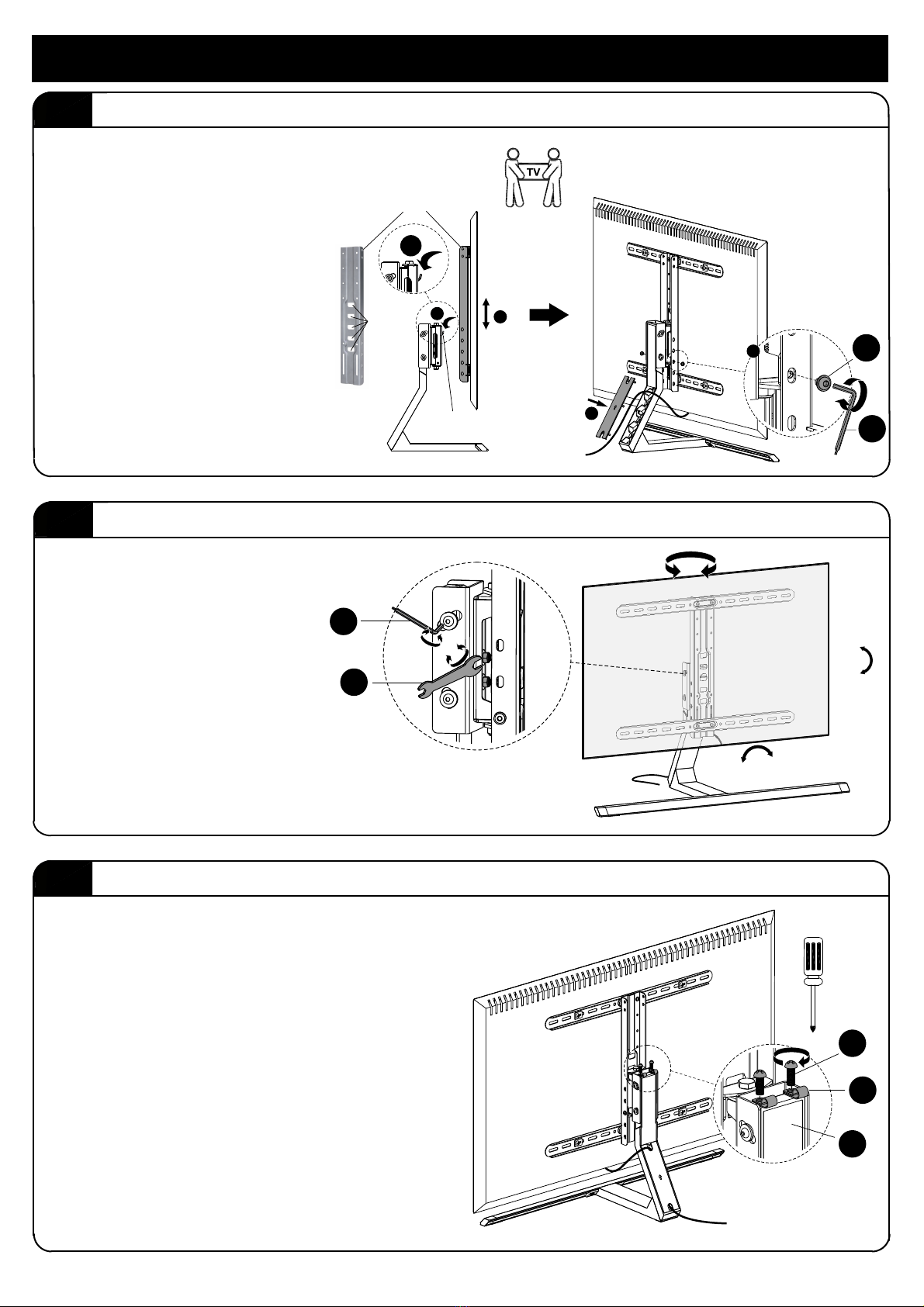
4.2 Adjust TV tilt, level and swivel.
Attach and secure Stand to TV.4.1
STEP 4 Attach, adjust and lock Stand to TV
4.3 Attach Cable Clamps to Stand.
Attach two cable clamps (N) with
two screws (L) into the top of the
Stand arm (A). Tighten with a Phillips
screwdriver (not included).
±35°
+5°
-10°
+3 ° - 3 °
Adjust the tilt (+5° to -10°)
and level (+3° to -3°). Then
tighten two captive screws
with the larger Allen wrench
(S). Finally, adjust the swivel
(+35° to -35°) and tighten
captive screws with open
wrench (T).
1
2
4
3
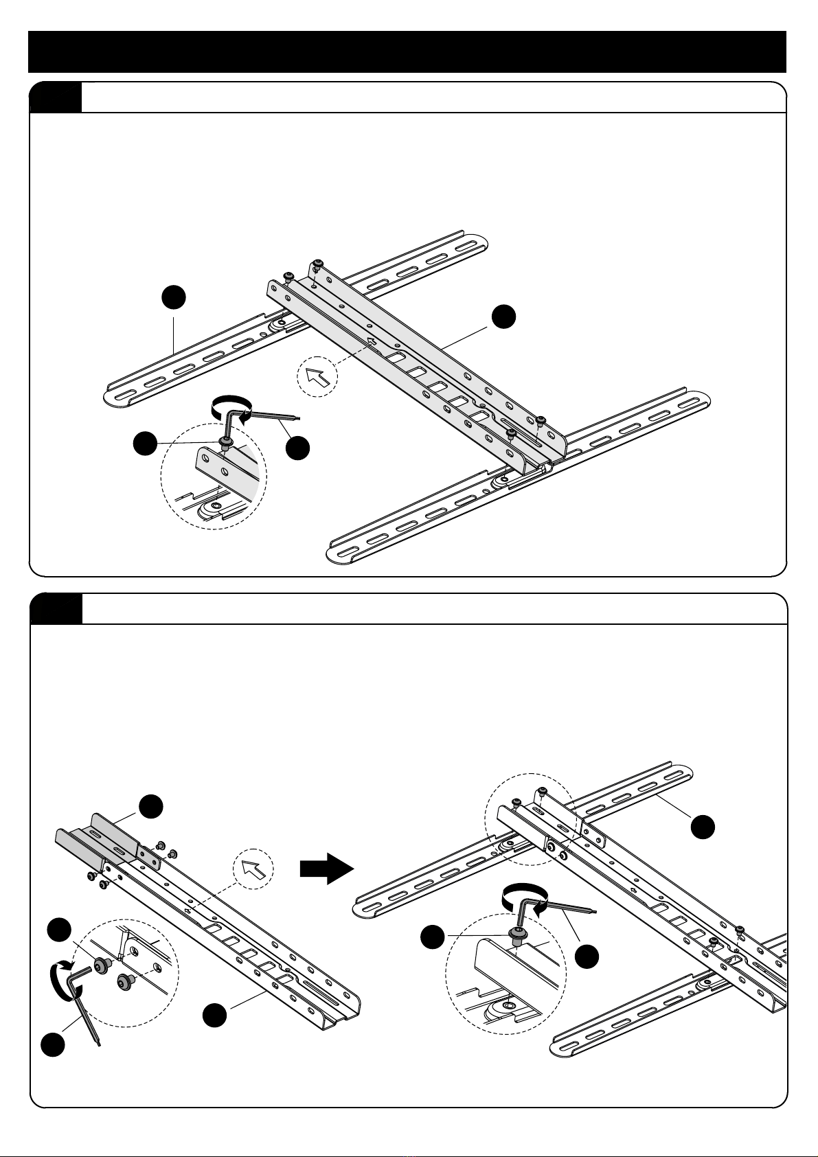
Vertical Bar
Two people must hold the TV.
[1] Lift the TV so the hook on the
stand is below the connection
latch.
[2] Look behind the TV to
align the hook and latch to
the desired height (5 levels).
Don’t let go of the TV until it
is secured.
[3] Then secure with locking
screws (I) on either side using
the larger Allen wrench (S).
[4] Route cables and attach
cover plate.
Hook
Latch
I
S
T
S
L
N
A
7