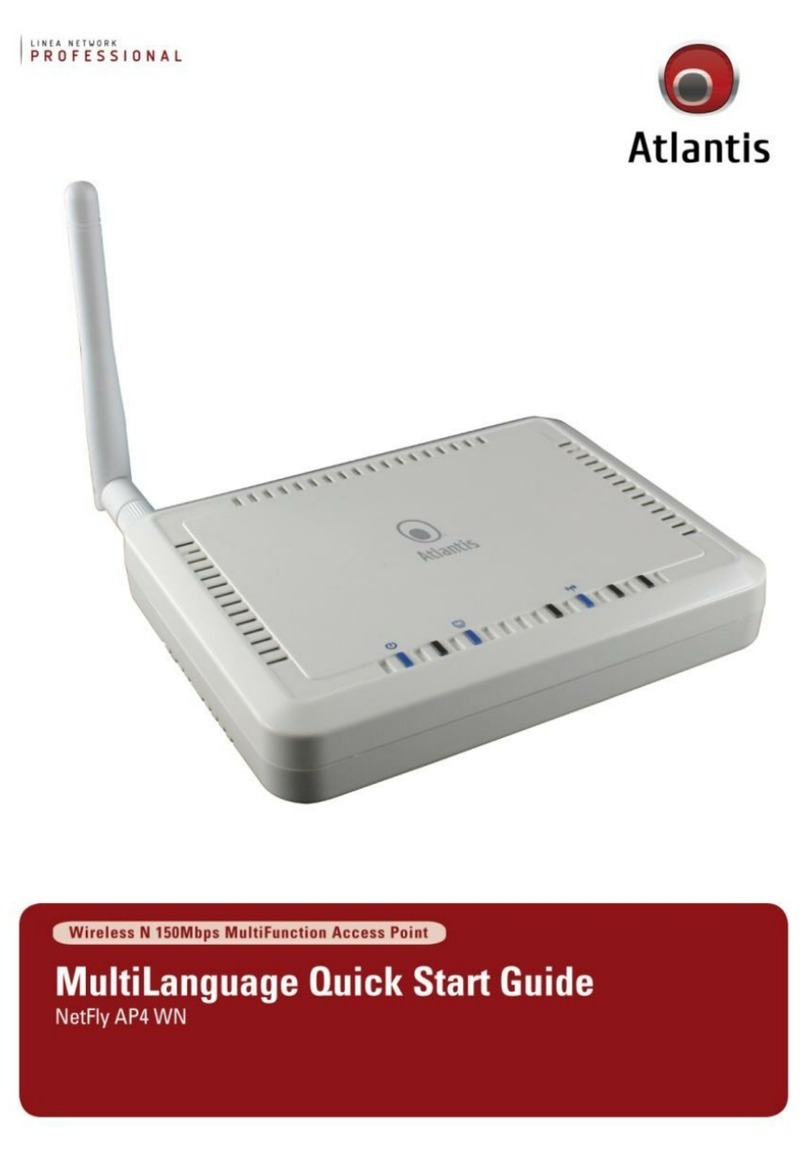
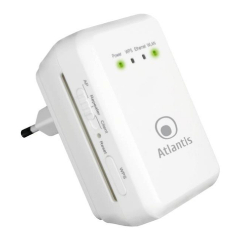
Atlantis NetFly AP4 WN User manual


2
ITALIANO
Questo prodotto è coperto da garanzia Atlantis della durata di 2 anni. Per maggiori
dettagli in merito o per accedere alla documentazione completa in Italiano fare
riferimento al sito www.atlantis-land.com.
ENGLISH
This product is covered by Atlantis 2 years warranty. For more detailed informations
please refer to the web site www.atlantis-land.com.
For more detailed instructions on configuring and using this device, please refer to
the online manual.
FRANCAIS
Ce produit est couvert par une garantie Atlantis de 2 ans. Pour des informations
plus détaillées, référez-vous svp au site Web www.atlantis-land.com.
DEUTSCH
Dieses Produkt ist durch die Atlantis 2 Jahre Garantie gedeckt. Für weitere
Informationen, beziehen Sie sich bitte auf Web Site www.atlantis-land.com.
ESPAÑOL
Este producto esta cubierto por Atlantis con una garantía de 2 años. Para mayor
información diríjase a nuestro sitio Web www.atlantis-land.com.

3
INDEX
1. Product Overview ............................................................................. 10
1.1 System Requirements ................................................................ 11
1.2 Package contents....................................................................... 11
1.3 Front LEDs ................................................................................ 11
1.4 Rear panel and ports.................................................................. 12
1.5 Cabling ...................................................................... 13
1.6 Factory Default Settings ............................................................. 13
1.7 TCP/IP Configuration.................................................................. 14
Windows 2000................................................................................. 14
Windows XP ....................................................... 15
Windows VISTA............................................................................... 15
Configuring PC (Windows 7)........................................................... 15
2. Configuring NetFly AP4 ..................................................................... 16
2.1 Browser configuration ................................................................ 16
2.2 Switching between Operating Modes........................................... 17
3. WEB Configuration............................................................................ 19
3.1 System ....................................................................... 19
3.1.1 Status......................................................................... 20
3.1.2 Schedule..................................................................... 21
3.1.3 Event Log ................................................................... 22
3.1.4 Monitor ....................................................................... 23
3.1.4.1 Switching between Operating Modes ............................ 25
3.1.4.2 Access Point Operating Mode ....................................... 26
3.1.4.2.1 Status......................................................................... 27
3.1.4.2.2 Basic........................................................................... 28
3.1.4.2.3 Advanced.................................................................... 30
3.1.4.2.4 Wireless Security Mode ................................................ 32
3.1.4.2.4.1 Security Disabled......................................................... 32
3.1.4.2.4.2 WEP (Wired Equivalent Privacy) ................................... 34
3.1.4.2.4.3 WPA (Wi-Fi Protected Access) / Pre-shared Key............. 37
3.1.4.2.4.4 WPA RADIUS (802.1x) ................................................. 39
3.1.4.2.5 Filter........................................................................... 41
3.1.4.2.6 Client List.................................................................... 42
3.1.4.2.7 VLAN .......................................................................... 43

4
3.1.4.2.8 WMM (Wireless Multimedia) ......................................... 43
3.1.4.3 Client Bridge Operating Mode....................................... 44
3.1.4.3.1 Status......................................................................... 45
3.1.4.3.2 Basic........................................................................... 45
3.1.4.3.3 Advanced.................................................................... 47
3.1.4.3.4 AP Profile .................................................................... 48
3.1.4.3.4.1 Manage AP Profile ....................................................... 48
3.1.4.3.5 WMM (Wireless Multimedia) ......................................... 49
3.1.4.4 WDS Operating Mode .................................................. 50
3.1.4.4.1 Status......................................................................... 51
3.1.4.4.2 Basic........................................................................... 51
3.1.4.4.3 Advanced.................................................................... 54
3.1.4.4.4 WMM (Wireless Multimedia) ......................................... 55
3.1.4.5 Repeater Operating Mode ............................................ 57
3.1.4.5.1 Status......................................................................... 58
3.1.4.5.2 Basic........................................................................... 58
3.1.4.5.3 Advanced.................................................................... 61
3.1.4.5.4 Wireless Security Mode ................................................ 63
3.1.4.5.4.1 Security Disabled......................................................... 63
3.1.4.5.4.2 WEP (Wired Equivalent Privacy) ................................... 64
3.1.4.5.4.3 WPA (Wi-Fi Protected Access) / Pre-shared Key............. 66
3.1.4.5.5 Filter........................................................................... 68
3.1.4.5.6 Client List.................................................................... 69
3.1.4.5.7 WMM (Wireless Multimedia) ......................................... 69
3.2 Network...................................................................... 70
3.2.1 Status......................................................................... 70
3.2.2 LAN / DHCP Client, Server............................................ 70
3.3 Management ............................................................... 72
3.3.1 Admin......................................................................... 72
3.3.2 SNMP.......................................................................... 73
3.3.3 Firmware Upgrade....................................................... 74
3.3.4 Restore to Factory Default ........................................... 75
3.3.5 Backup Settings........................................................... 76
3.3.6 Restore Settings .......................................................... 76
3.3.7 Reset.......................................................................... 76
3.4 Tools .......................................................................... 77

5
3.4.1 Time Setting ............................................................... 77
3.4.2 Diagnosis .................................................................... 78
4. Support............................................................................................ 79
APPENDIX
APPENDIX A: Troubleshooting............................................................... 80
A.1 Using LEDs to diagnose problems ............................................... 80
A.1.1 Power LED ............................................................................. 80
A.1.2 LAN LED................................................................................. 80
A.2 WEB Configurator ...................................................................... 80
A.4 Login Username e Password....................................................... 81
A.5 LAN Interface ............................................................................ 81
A.6 Frequently Asked Question......................................................... 82
APPENDIX B: Country Channel List ........................................................ 85
APPENDIX C: Technical Features ........................................................... 86
A02-AP4-WN(v1.0)_ME01 (July 2010)

6
Copyright Statement
No part of this publication may be reproduced, stored in a retrieval system, or
transmitted in any form or by any means, whether electronic, mechanical,
photocopying, recording or otherwise without the prior writing of the publisher.
Windows™ 98SE/2000/ME/XP/VISTA are trademarks of Microsoft® Corp. Pentium is
trademark of Intel. All copyright reserved.
The Atlantis logo is a registered trademark of Atlantis. All other names mentioned
mat be trademarks or registered trademarks of their respective owners. Subject to
change without notice. No liability for technical errors and/or omissions.
Wireless LAN, Health and Authorization for use
Radio frequency electromagnetic energy is emitted from Wireless LAN devices. The
energy levels of these emissions however are far much less than the
electromagnetic energy emissions from wireless devices like for example mobile
phones. Wireless LAN devices are safe for use frequency safety standards and
recommendations. The use of Wireless LAN devices may be restricted in some
situations or environments for example:
On board of airplanes, or
In an explosive environment, or
In case the interference risk to other devices or services is perceived or
identified as harmful
In case the policy regarding the use of Wireless LAN devices in specific
organizations or environments (e.g. airports, hospitals, chemical/oil/gas industrial
plants, private buildings etc.) is not clear, please ask for authorization to use these
devices prior to operating the equipment.
Regulatory Information/disclaimers
Installation and use of this Wireless LAN device must be in strict accordance with
the instructions included in the user documentation provided with the product. Any
changes or modifications made to this device that are not expressly approved by the
manufacturer may void the user‟s authority to operate the equipment. The
Manufacturer is not responsible for any radio or television interference caused by
unauthorized modification of this device, of the substitution or attachment.
Manufacturer and its authorized resellers or distributors will assume no liability for
any damage or violation of government regulations arising from failing to comply
with these guidelines.
CE Mark Warning
In a domestic environment, this product may cause radio interference, in which case
the user may be required to take adequate measures.

7
CE in which Countries where the product may be used freely:
Germany, UK, Italy, Spain, Belgium, Netherlands, Portugal, Greece, Ireland,
Denmark, Luxembourg, Austria, Finland, Sweden, Norway and Iceland.
France: except the channel 10 through 13, law prohibits the use of other channels.
CE/EMC Restriction of Liability
The product described in this handbook was designed, produced and approved
according to the EMC-regulations and is certified to be within EMC limitations.
If the product is used in an uncertified PC, the manufacturer undertakes no
warranty in respect to the EMC limits. The described product in this handbook was
constructed, produced and certified so that the measured values are within EMC
limitations. In practice and under special circumstances, it may be possible, that
the product may be outside of the given limits if it is used in a PC that is not
produced under EMC certification. It is also possible in certain cases and under
special circumstances, which the given EMC peak values will become out of
tolerance. In these cases, the user himself is responsible for compliance with the
EMC limits.
Declaration of Conformity
This equipment has been tested and found to comply with Directive 1999/5/CE of
the European Parliament and of the Council on radio equipment and
telecommunications terminal equipment and the mutual recognition of their
conformity. After assessment, the equipment has been found to comply with the
following standards: EN 300.328 (radio), EN 301 489-1, EN 301 489-17
(electromagnetic compatibility) and EN 60950 (safety). This equipment may be used
in all European Union contries and in all countries applying Directive 1999/5/CE,
without restriction, with the exception of the following countries:
France (FR):
When this equipment is used outdoors, output power is limited to
within the frequency bans listed on the chart. For more info, consult the website
www.art-telecom.fr.
Location
Frequency Band (MHz)
Power (EIRP)
Indoor (no restriction)
2400-2483,5
100mW(20dBm)
Outdoor
2400-2454
2454-2483,5
100mW(20dBm)
10mW(10dBm)
Italy(IT):
For more info, consult the website
www.comunicazioni.it
Luxembourg:
General authorization requie for network and service supply.

8
Norway (NO):
This subsection does not apply for geographical area within a radius
of 20 km from the center of Ny Alesund.
Russia (CCP):
only for indoor application.
Declaration of Conformity
Hereby We declare that this product is in compliance with the essential
requirements and other relevant provisions of Directive “Electromagnetic
Compatibility” and 1999/5/CE within CE Marking Requirememnt.
CE Declaration is available on the web site www.atlantis-land.com.
Important information for the correct recycle/treatment
procedures of this equipment
The crossed-out wheeled bin symbol printed on the unit label or unit packaging
indicates that this equipment must not be disposed of as unsorted municipal waste
but it should be collected separately.
The waste of electric and electronic equipment must be treated separately, in order
to ensure that hazardous materials contained inside the equipment are not buried
thereby providing potential future problems for the environment and human health.
Moreover, it will be possible to reuse and recycle some parts of the waste of electric
and electronic equipment, contributing to reduce the quantities of waste to be
disposed of and the depletion of natural resources.
As user of this equipment, you are responsible to return this waste of electronic
equipment to an authorised collection facility set up by your Municipality. More
detailed information on your nearest collection centre can be obtained from your
Municipality or from other competent local entities.
If you are replacing the old equipment with a new equivalent product, the
distributor must take-back the old equipment free of charge on a one-to one basis
as long as the equipment is of equivalent type and fulfilled the same functions as
the supplied equipment.
Your rôle in participating to the separate collection of waste of electric and
electronic equipment is essential to ensure that environmental protection and

9
human health objectives connected to a responsible treatment and recycling
activities are achieved.
PS.: The above mentioned information are reported herewith in compliance with Directive
2002/96/CE, which requires a separate collection system and specific treatment and disposal
procedures for the waste of electric and electronic equipments (WEEE). For further and more
detailed information, we invite you to visit our website at www.atlantis-land.com
CE Logo with attention Mark ( ) aren‟t fully
compliant with minimum dimensions requirement to
European Directive due to limited sticker area.
WEEE BIN Logo ( ) isn‟t fully compliant with
minimum dimensions requirement to European Directive
due to limited sticker area.
Atlantis suggest to vistit the web site www.atlantis-
land.com in order to retrieve update manual, techsheet
and driver.
Before starting, take a few minutes to read this manual.
Read all of instructions and save this manual for later
reference.

10
Thank You for choosing an Atlantis Product. For more detailed instructions on
configuring and using the NetFly AP4, please refer to the online manual into CD.
1. Product Overview
IEEE 802.11n Wireless
Thanks to its embedded Access Point, based on the most recently 802.11n
specifications, is possible to create high performance WLANs with extended
coverage. NetFly AP4 is designed to operate in every working environment
(domestic or SoHo).
No more dead zones and high speed (up to 6 times than traditional IEEE802.11b/g
networks) are the most impressive characteristics of this innovative wireless
technology, that ensure excellent throughtput performances merging with total
freedom of mobility.
The chipsets fully support Wi-Fi Protected Access (WPA/WPA2) and the IEEE802.1x
(Supplicant function in CB mode) security standards in hardware and high-speed
encryption engines with no performance degradation.
Multi-Function Access Point
The WDS (up to 4 AP) feature makes the device an ideal solution for quickly
creating and extending a wireless local area network (WLAN) in offices or other
workplaces. A pair of Wireless Multi-Function APs operating under Bridge mode to
act as the bridge that connect two Ethernet networks or Ethernet enabled clients
together.
Repeater Mode is able to extend the effective range and coverage of the wireless
network.
Last but not least the AP will be a Wireless Ethernet Adapter transforms any
Ethernet-enabled (Console, Pinter, DLNA player, TV, NAS) devices to have the
wireless function.
When Router function is enabled, it is possible to add between the 2 interfaces,
Wireless and Ethernet, different services (NAT, firewall and QoS).
Virtual AP
The device supports up to 4 SSIDs (client isolation) with VLAN tag that allows
NetFly to perform as multiple virtual access points.
Wall Plug mount and compact size for an easy installation.

11
1.1 System Requirements
Before installing Router, your PC should meet the following:
TCP/IP protocol must be installed on each PC
Web browser, such as Microsoft Internet Explorer 5.0 or later, Netscape
Navigator 6.0 or later
1.2 Package contents
Unpack the package and check all the items carefully. Also, keep the box and
packing materials in case you need to ship the unit in the future. The package
should contain the following items:
NetFly AP4
Power Adapter AC-DC (12V, 1A)
UTP cat. 5 cable (RJ-45 connector), 2 dBi Antenna
Quick Start Guide (English, Italian and French)
Cd-Rom contained manual
Warranty Card & WEEE Disclaimer
If any item contained is damaged or missing, please contact your local
dealer as soon as possible.
1.3 Front LEDs
LED
MEANING
PWR
Lit Blue when power is plugged in and the system is
ready.

12
LAN
Lit when connected to Ethernet device (Blue for
10/100Mbps)
Blinking when data transmit/received.
WLAN
Flashes when sending/receiving data. Lit blue when the
wireless connection is established
1.4 Rear panel and ports
PORT
MEANING
DC-IN
Connect the supplied power adapter to this jack.
RJ45(LAN)
Connect an UTP Ethernet cable to one of the four LAN
ports when connecting to a PC or an office/home network
of 10Mbps or 100Mbps.
Reset
After the device has turned on, press it to reset (10
seconds or above) the device will be restored to factory
default settings (this is used when you can not login to
the router, e.g. forgot the password)
R-SMA
Connect the supplied Antenna here.

13
1.5 Cabling
First you must connect the product to the RJ45 ports the PCs of your Lan or others
Switch. In the end connect the DC Adapter to the socket then to the NetFly AP4.
Once you‟ve done all the connections the product will carry on immediately a
autotest (120 seconds). With the power source on, once the device is connected,
the Power, LAN and WLAN port LEDs will light up indicating a normal status.
If the LAN Port‟s Link indicator does not light up then check the RJ-45 cable if it is
firmly feed to the RJ45 port, while the LAN is link up to the Switch/Hub, the LAN
port‟s LED will light up.
The control LEDs of the device are clearly visible and the status of the network link
can be seen instantly.
1.6 Factory Default Settings
The Wireless Multi-Function Access Point can be configured with your Web browser.
The product provides a very easy and user-friendly interface for configuration.

14
This section describes the configuration required by LAN-attached PCs that
communicate with the Wireless Multi-Function Access Point, either to configure the
device or for network access. These PCs must have an Ethernet interface (or
wireless adapter) installed properly, be connected to the Wireless Multi-Function
Access Point either directly or through an external repeater hub or by wireless, and
have TCP/IP installed and configured with a fixed IP address that must be in the
same subnet of the Wireless Multi-Function Access Point. The default IP address of
the Wireless Multi-Function Access Point is 192.168.1.2 and subnet mask is
255.255.255.0. For example, when the default network address of the default IP
address of the AP is 192.168.1.1, then the manager PC should be set at 192.168.1.x
(where x is a number between 5 and 254), and the default subnet mask is
255.255.255.0.
Please follow the steps below for PC‟s network environment installation. First of all,
please check your PC‟s network components. The TCP/IP protocol stack and
Ethernet network adapter must be installed. If not, please refer to MS Windows
related manuals.
Before you configure this Wireless Multi-Function Access Point, you need to know
the following default settings:
Username:admin
Password: atlantis
IP LAN address: (192.168.1.2), Subnet Mask (255.255.255.0)
DHCP Server: disable
Mode: Client Bridge
When NetFly AP4 works as Access Point/Bridge the IP
192.168.1.1.
1.7 TCP/IP Configuration
Windows 2000
Go to Start / Settings / Control Panel. In the Control Panel, double-click
on Network and Dial-up Connections.
Double-click LAN Area Connection.
In the LAN Area Connection Status window, click Properties.
Select Internet Protocol (TCP/IP) and click Properties.
Select Use the Following IP Address (EG IP=192.168.1.5 and subnet
Mask=255.255.255.0).
Click OK to finish the configuration.

15
Windows XP
Go to Start / Control Panel (in Classic View). In the Control Panel,
double-click on Network Connections.
Double-click LAN Area Connection.
In the LAN Area Connection Status window, click Properties.
Select Internet Protocol (TCP/IP) and click Properties.
Select Use the Following IP Address (EG IP=192.168.1.5 and subnet
Mask=255.255.255.0).
Click OK to finish the configuration.
Windows VISTA
Go to Start -> Control Panel (in Classic View). In the Control Panel,
double-click on Network and Sharing Center icon.
Click Manage Network connections then double-click Local Area
Connection and click Properties.
Click Continue (Windows needs your permission to continue).
Select Internet Protocol (TCP/IP) and click Properties.
Select Use the Following IP Address (EG IP=192.168.1.5 and subnet
Mask=255.255.255.0).
Click OK to finish the configuration.
Configuring PC (Windows 7)
Go to Start / Control Panel (select Large/Small Icon). In the Control
Panel, double-click on Network and Sharing Center icon.
Click Change Adapter Settings then double-click Local Area Connection
(or Wireless) and click Properties.
Click Continue (Windows needs your permission to continue).
Select Internet Protocol (TCP/IP) and click Properties.
Select Use the Following IP Address (EG IP=192.168.1.5 and subnet
Mask=255.255.255.0).
Click OK to finish the configuration.

16
2. Configuring NetFly AP4
2.1 Browser configuration
Open the web browser, enter the local port IP address of this NetFly AP4, which
default at 192.168.1.2, and click Go to get the login page.
The default username is admin, password atlantis and click OK to continue. At
the configuration homepage, the left navigation pane where bookmarks are
provided links you directly to the desired setup page, including:
System
Wireless
Network
Management
Tools
Logout
Click on the desired item to expand the page with all settings in the main
navigation panel.

17
2.2 Switching between Operating Modes
Click on the System link on the navigation drop-down menu. You will then see five
options: Operation Mode, Status, Schedule, Event Log, and Monitor. Click on
Operation Mode. A dialog box will appear to notify you that the system will
restart in order for the change to take effect. Click on the OK button to continue.
Client Wireless (Operation Mode=Client Bridge, Router Function=disable):
transforms any Ethernet-enabled (Console, Pinter, DLNA player, TV, NAS)
devices to have the wireless function.
Client Wireless Router (Operation Mode=Client Bridge, Router
Function=disable): In order to configure NetFly AP4 as a Router, select Access
Client Bridge with Router function from the Operating Mode drop-down list.
Access Point (Operation Mode=Access Point, Router Function=disable): In
order to configure NetFly AP4 as an Access Point, select Access Point from the
Operating Mode drop-down list. IP is 192.168.1.1
Router (Operation Mode=Access Point, Router Function=enable): In order to
configure NetFly AP4 as a Router, select Access Point with Router function
from the Operating Mode drop-down list. IP is 192.168.1.1
WDS Bridge (Operation Mode=WDS Bridge): The WDS (up to 4 AP) feature
makes the device an ideal solution for quickly creating and extending a
wireless local area network (WLAN) in offices or other workplaces. A pair of
Wireless Multi-Function APs operating under Bridge mode to act as the bridge
that connect two Ethernet networks or Ethernet enabled clients together. IP
is 192.168.1.1
Universal Repeater (Operation Mode=Repeater):NetFly AP4 is able to
extend the effective range and coverage of the wireless network.

18
A dialog box will appear to notify you that the system will restart in order for the
change to take effect. Click on the OK button to continue
For more detailed instructions on configuring and using the NetFly AP4, please refer
to the online manual into CD.

19
3. WEB Configuration
3.1 System
Click on the System link on
the navigation drop-down menu. You will
then see five options: Operation Mode,
Status, Schedule, Event Log, and Monitor.
Each option is described in detail below.

20
3.1.1 Status
Click on the Status link under the System drop-down menu. The status
page displays a summary of current system settings. Information such
as operating mode, system up time, firmware version, serial number,
kernel version and application version are displayed in the „System‟
section. LAN IP address, subnet mask, and MAC address are displayed in
the „LAN‟ section. In the „WLAN‟ section, the frequency, channel is
displayed. Since this device supports multiple-SSIDs, the details of each
SSID, such as ESSID and its security settings are displayed in the
„SSID_#‟ section.
Other manuals for NetFly AP4 WN
1
Table of contents
Other Atlantis Wireless Access Point manuals

Atlantis
Atlantis NetFly AP4 W300N+ User manual

Atlantis
Atlantis NetPower 303 WN User manual

Atlantis
Atlantis NetFly AP5 W300N User manual

Atlantis
Atlantis A02-AP2-W54M User manual

Atlantis
Atlantis NetFly AP4 WN User manual

Atlantis
Atlantis NetFly A02-AP1-W54 User manual

Atlantis
Atlantis NetFly AP3 WN User manual
Popular Wireless Access Point manuals by other brands

SMC Networks
SMC Networks EZ Connect SMCWEB-N Quick installation guide

Tosibox
Tosibox Lock 100 user manual

4IPNET
4IPNET EAP717 Quick installation guide

Sony
Sony PCWA-A100 - Wireless Lan Access Point operating instructions

D-Link
D-Link AirPremier N DAP-2690 user manual

HP
HP Aruba 310 Series installation guide