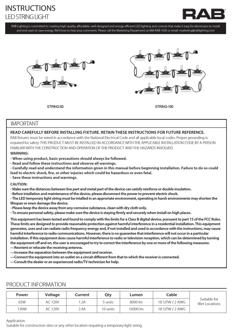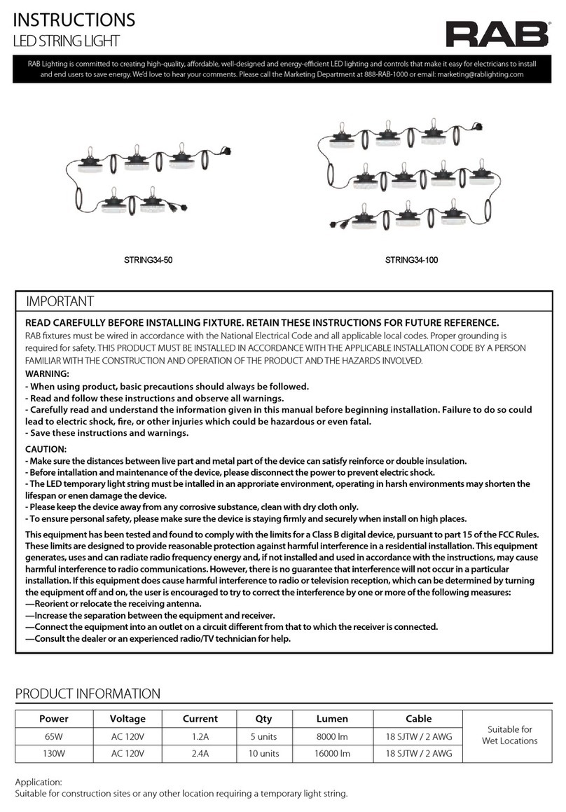
SUITABLE FOR BELOW LAMP
1. 8-80W LED products with 0-10V dimming capability, and ensure
the LED product system power below 20W when dimming to 1V.
2. 8-21W LED products without 0-10V dimming capability also can
be used.
TEST SWITCH
Emergency kit will go into emergency mode if test switch
is pressed when main supply is on, while it will go into
charging mode if test switch is not pressed.
Note: These instructions do not cover all details or variations in equipment nor do they provide for every possible situation during installation, operation or maintenance.
LED INDICATOR
1. Red stable: charging mode or fully charged.
2. Red o: main power o or discharging mode.
3. 2 second slow ashing (compatibility test standby mode):
represents that the battery is at a low voltage and needs
charging.
CLEAR FAILURE MODE
Check wiring, solve the problem and connect mains power. Then
press test button and go to compatibility test, LED indicator will
be permanent red if compatibility test passes, meanwhile failure
mode is removed.
TESTING PROCEDURES
1. Press the test button to cut the power to the AC driver and
switch the system to emergency mode.
2. Release the test button to return to normal mode.
3. Switch o the circuit breaker to simulate a full power outage.
Monthly
1. Ensure that the test button light is illuminated.
2. Conduct a 30-second discharge test by depressing the test
button.
3. The LED load should operate at reduced output.
Annually
1. Allow a 24-hour charge before conducting test.
2. Ensure that the test button light is illuminated.
3. Conduct a full 90-minute discharge test.
4. The unit should operate as intended for the duration of the test.
Written records of the testing shall be kept by the owner for inspection
by the authority having jurisdiction.
SERVICING SHOULD BE PERFORMED BY QUALIFIED PERSONNEL.
FAILURE MODE
0.5 second fast ashing-represents failure mode (No battery or
open circuit in emergency mode or LED load wattage is higher than
nominal emergency power).
EMERGENCY DRIVER
and
end
users
to
save
energy
.
We
’
d
love
to
hear
your
comments.
Please
call
the
Marketing
Depar
tment
at
888-RAB-1000
or
email:
[email protected]INSTRUCTIONS
MOUNTING METHOD (cont’d)
Mounting method 2
With Straps (Fig. 2)
Run the straps through the mounting tabs of the unit for
securing to a beam or column near the xture. Multiple strap kits
can be used in conjunction with each other for larger diameter
requirements.
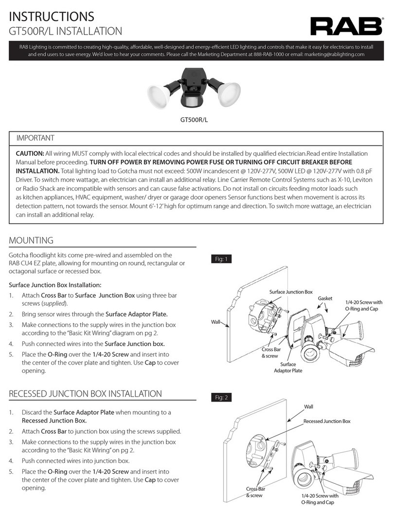
DRI-21-EMGR-DC-D10

