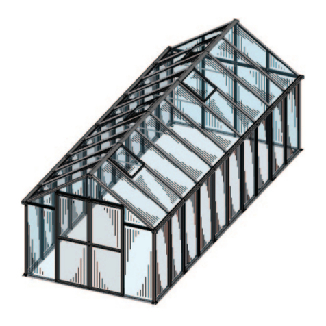
Atlas SCHOLAR Series User manual

Contractors/Installers Note:
This manual is the property of the customer. Please leave it in the possession of the customer.
SCHOLAR
SERIES GREENHOUSE
Assembly Instructions
Applies to
16’ Wide

Greenhouse in accordance with your Order.
This Instruction Manual is specifically made for and has been customized for your
Thank you for choosing Atlas Manufacturing, Inc.
The Greenhouse described in this manual is a "Cold Frame" structure. It is intended for
early spring coverage and is classified as a "Non-Coded Greenhouse". It is designed for
a limited amount of wind and snow but is not designed for typical wind, snow, ice, and
Thank you again for choosing Atlas
structural failure and/or damages including but not limited to collateral damage resulting
in financial losses or personal injury due to this Non-coded Structure not complying with
your local code requirements
Atals Manufacturing, Inc. cannot and will not be held liable or responsible for
siesmic conditions referred to as "Loads" required by most local building authorities.


!! IMPORTANT!!
Footings and/or foundations shown in the following pages of this
manual are intended as a guideline only and may not be correctly
sized for your building.
Soil types and densities vary from location to location even within
your county. Larger footings may be required based on your specific
soil conditions and other factors including the spacing of your posts
(4', 5' or 6' etc. on center), wind load, and snow load.
Atlas Manufacturing, Inc. can provide, upon your request, the
building "reactions" (engineering calculations) to assist you in
determining your actual foundation requirements.
It is the responsibility of the customer to install this structure on an
adequate foundation designed to meet the local building codes. This
information can be obtained from your local code enforcement
department. REMEMBER: Your structure is only as strong as your
foundation.

IMPORTANT NOTICE
WE DO NOT GUARANTEE SAFE DELIVERY

WARRANTIES & DISCLAIMERS
AT ATLAS MANUFACTURING, INC., WE TAKE PRIDE IN OUR WORKMANSHIP AND STRIVE TO PROVIDE OUR
CUSTOMERS WITH THE BEST STRUCTURES AND EQUIPMENT FOR THE MONEY. WE ARE MAKING EVERY EFFORT
TO ENSURE THAT YOUR DECISION TO BUY ONE OF OUR GREENHOUSES IS A HAPPY ONE FOR YEARS TO COME.
TO HELP ENSURE THAT OUR GREENHOUSES CONTINUE TO BE OF HIGH QUALITY AFTER THEY LEAVE OUR
ESTABLISHMENT, WE HAVE PUT TOGETHER THESE PAGES OF WARNINGS AND RECOMMENDATIONS. PLEASE
READ THEM CAREFULLY AND KEEP FOR FUTURE REFERENCE. PURCHASER UNDERSTANDS AND RECOGNIZES
THAT GREENHOUSES AND RELATED PRODUCTS MANUFACTURED AND/OR SOLD BY ATLAS MANUFACTURING,
INC. ARE SUBJECT TO VARIED CONDITIONS DUE TO THE MANNER IN WHICH THEY ARE TO BE INSTALLED AND
USED. PURCHASER FURTHER RECOGNIZES AND AGREES THAT SUITABILITY OF ANY PRODUCT SOLD OR
MANUFACTURED BY ATLAS MANUFACTURING, INC. FOR A PARTICULAR APPLICATION IS THE PURCHASER'S
DECISION AND THAT THE PURCHASER IS NOT RELYING ON THE SKILL OR JUDGMENT OF ATLAS
MANUFACTURING, INC. REGARDING SUITABILITY OF ANY PRODUCT OR SERVICE. ATLAS MANUFACTURING, INC.
MAKES NO WARRANTIES WHATSOEVER, EXPRESSED OR IMPLIED, ORAL OR WRITTEN TO PURCHASER. LIABILITY
IS LIMITED TO REPAIR OR REPLACEMENT OF DEFECTIVE PARTS TO ORIGINAL PURCHASER. ATLAS
MANUFACTURING, INC. IS NOT LIABLE FOR ANY CONSEQUENTIAL DAMAGES, EXPENSES, OR INJURY ARISING
FROM THE USE, MISUSE, OR ADVERSE WEATHER OF ANY PRODUCT MANUFACTURED OR SOLD BY ATLAS
MANUFACTURING, INC. THERE IS NO WARRANTY OF ADVERSE WEATHER CONDITIONS OR MERCHANTABILITY.
ATLAS MANUFACTURING, INC. RESERVES THE RIGHT TO MAKE CHANGES IN DESIGN OR ADD TO OR IMPROVE
THEIR PRODUCT WITHOUT INCURRING ANY OBLIGATION TO INSTALL THE SAME ON ANY PRODUCTS
PREVIOUSLY MANUFACTURED. THIS WARRANTY SHALL NOT APPLY TO ANY PRODUCT WHICH HAS BEEN
ALTERED IN ANY WAY SO AS IN OUR JUDGMENT TO AFFECT ITS INTENDED USE; NOR WHICH HAS BEEN SUBJECT
TO IMPROPER INSTALLATION, MISUSE, ABUSE, NEGLIGENCE OR ANY OTHER OCCURRENCE BEYOND THE
CONTROL OF ATLAS MANUFACTURING, INC.
ATLAS MANUFACTURING, INC. CANNOT AND WILL NOT BE HELD RESPONSIBLE FOR PRODUCT OR EQUIPMENT
FAILURE WHERE EXCESSIVE WEATHER CONDITIONS SUCH AS SNOW, WIND, FIRE, OR HAIL HAS OCCURRED, AND
SUCH OCCURRENCES HAVE EXCEEDED THE DESIGN LOADS STATED IN ENGINEERING SPECIFICATIONS.
FURTHERMORE, ATLAS MANUFACTURING, INC. CANNOT AND WILL NOT BE HELD RESPONSIBLE FOR PRODUCT
OR EQUIPMENT FAILURE DUE TO IMPROPER INSTALLATION, INADEQUATE COMMON MAINTENANCE OR
FAILURE TO FOLLOW THE MANUFACTURER'S RECOMMENDATIONS AND INSTRUCTIONS. FAILURE TO FOLLOW
MANUFACTURER'S RECOMMENDATIONS AND INSTRUCTIONS COULD RESULT IN ULTIMATE STRUCTURE AND
EQUIPMENT FAILURE.
ATLAS MANUFACTURING, INC. CANNOT AND WILL NOT BE HELD RESPONSIBLE FOR STRUCTURAL DAMAGE, LOSS
OF INCOME, BODILY INJURY OR PROPERTY DAMAGE DUE TO FIRE. THE FOUNDATION DRAWINGS ARE EXAMPLES
ONLY. THESE DRAWINGS DO NOT TAKE INTO ACCOUNT VARIOUS SOIL TYPES AND LOCAL CODES. YOU MUST
HAVE A LOCAL ENGINEER DESIGN A PROPER FOUNDATION FOR YOUR SOIL TYPE. ATLAS MANUFACTURING, INC.
DISCLAIMS ALL RESPONSIBILITY FOR ANY INJURY OR DAMAGE CAUSED BY THE GREENHOUSE OR EQUIPMENT.
IT IS THE CUSTOMER'S RESPONSIBILITY TO OBTAIN ALL NECESSARY PERMITS. ATLAS-MANUFACTURING, INC.
CANNOT AND WILL NOT BE HELD RESPONSIBLE FOR PRODUCT FAILURE WHERE EXCESSIVE WEATHER
CONDITIONS SUCH AS SNOW, WIND, FIRE, OR HAIL HAVE OCCURRED, AND SUCH OCCURRENCES HAVE
EXCEEDED THE DESIGN LOADS STATED IN ENGINEERING SPECIFICATIONS. FURTHERMORE, ATLAS
MANUFACTURING, INC. CANNOT AND WILL NOT BE HELD RESPONSIBLE FOR PRODUCT FAILURE DUE TO
IMPROPER INSTALLATION OR FAILURE TO FOLLOW THE MANUFACTURER'S RECOMMENDATIONS AND
INSTRUCTIONS. IT IS THE CUSTOMER'S RESPONSIBILITY TO UNDERSTAND: PROPER INSTALLATION AND
MAINTENANCE AS DESCRIBED IN THIS MANUAL IS VITAL IN ACHIEVING SNOW AND WIND LOAD RATINGS. ATLAS
DISCLAIMS ALL RESPONSIBILITIES OF ANY INJURY OR DAMAGE CAUSED BY THE GREENHOUSES OR EQUIPMENT.
ATLAS, MANUFACTURING, INC. CANNOT AND WILL NOT BE HELD RESPONSIBLE FOR BODILY INJURY DURING
CONSTRUCTION. IT IS THE BUYER'S RESPONSIBILITY TO ADDRESS ALL SAFETY ISSUES WHEN RECEIVING HIS OR
HER ORDER AND DURING INSTALLATION.

EQUIPMENT WARRANTY & WARRANTY PROCEDURES
ATLAS MANUFACTURING, INC. IS A DISTRIBUTOR FOR PRODUCTS AND EQUIPMENT USED IN THE
GREENHOUSE INDUSTRY SUCH AS HEATERS, FANS, COVERINGS, PUMPS, CONTROLLERS, AND OTHERS.
THESE PRODUCT MANUFACTURERS HAVE SET FORTH WARRANTY PROCEDURES THAT MUST BE
FOLLOWED TO VALIDATE THE WARRANTY. WARRANTY PROCEDURES ARE NORMALLY FOUND IN THE
BOX WITH THE PRODUCT (I.E. MOTORS, CONTROLLERS, HEATERS, ETC). EACH PRODUCT MANUAL
SHOULD BE RETAINED FOR SERVICING THE PRODUCT AND WARRANTY PROCEDURES. IF THE SERVICE
MANUAL AND/OR WARRANTY PROCEDURE CANNOT LOCATED, CALL ATLAS MANUFACTURING, INC.
AND WE WILL ADVISE YOU OF THE NECESSARY PROCEDURES. PLEASE ASK FOR TECHNICAL SUPPORT.
PURCHASER UNDERSTANDS THAT THE COST OF STRUCTURAL CERTIFICATION NOT REQUESTED AT
TIME OF PURCHASE BUT REQUESTED AFTER PURCHASER RECEIVED STRUCTURE AND SIGNED DELIVERY
RECEIPT WILL BE CHARGED TO PURCHASER. IN ADDITION, ANY COMPONENTS (ADDITIONAL TRUSSES,
PURLINS, SPACINGS, BRACES, ETC.) NECESSARY TO MEET REQUIRED CERTIFICATION WILL BE CHARGED
TO THE PURCHASER. PURCHASER IS RESPONSIBLE FOR INFORMING ATLAS OF REQUIRED LOADS FOR
THE COUNTY IN WHICH THE STRUCTURE IS TO BE LOCATED.
IMPORTANT: INSPECT, IDENTIFY, AND RECOGNIZE ALL BUNDLES, PARTS, AND EQUIPMENT
PERTAINING TO YOUR ORDER BEFORE YOU START!!! WE HAVE FOUND MANY CLAIMS OF
SHORTAGES TO BE THAT THE CUSTOMER HAS THE PART BUT DOES NOT RECOGNIZE IT OR HAS
MISTAKENLY APPLIED THE PART TO THE GREENHOUSE IN THE WRONG PLACE.
IF YOU NEED ASSISTANCE, PLEASE CALL OUR SERVICE SUPPORT NUMBER AT (229) 532-2905 AND ASK
TO SPEAK TO TECHNICAL SUPPORT. ATLAS WILL WARRANTY ANY DEFECTIVE MOTOR OR PART FOR
FANS, SHUTTER, PUMP,
HEATER, THERMOSTAT OR CURTAIN MOTOR FOR 1 FULL YEAR. HOWEVER, ALL WARRANTIES WILL
BECOME NULL AND VOID WHEN IMPROPERLY WIRED OR USED. ATLAS WILL IMMEDIATELY SEND
REPLACEMENT MOTOR OR PART TO CUSTOMER AT NO CHARGE. HOWEVER, ATLAS REQUIRES
RECEIVING DEFECTIVE MOTOR OR PART WITHIN 10 DAYS OR CUSTOMER WILL BE BILLED. IN
ADDITION, IF UPON INSPECTION AND TESTING WE FIND THE MOTOR OR PART WAS IMPROPERLY
WIRED, CUSTOMER WILL BE BILLED.
ATLAS MANUFACTURING, INC. IS NOT RESPONSIBLE FOR LOSS OF INCOME, MERCHANDISE, OR
LIVELIHOOD DUE TO DEFECTIVE PART SOLD BY ATLAS MANUFACTURING, INC.
COMMENTS: OVER THE YEARS WE HAVE FOUND 90% OF CLAIMS OF A DEFECTIVE NEW
MOTOR OR PART TO BE CAUSED BY INITIAL IMPROPER WIRING. IN A GENUINE EFFORT TO LOOK
AFTER YOUR BEST INTERESTS, WE ENCOURAGE AND RECOMMEND THAT ALL MOTORS BE WIRED BY A
PROFESSIONAL EXPERIENCED IN WIRING COMMERCIAL MOTORS AND HEATERS.

WARRANTIES & RECOMMENDATIONS
WE RECOMMEND STORING ALL SQUARE AND RECTANGLE TUBING IN A DRY AREA. IN ADDITION, ALL GAL
VANIZED "HAT" (SHAPED) PURLINS MUST BE STORED IN A DRY AREA. SQUARE AND RECTANGLE TUBING AND
HAT PURLINS ARE BUNDLED IN TIGHT "NEST" BUNDLES WHICH DO NOT ALLOW AIR TO DRY OUT MOISTURE
INSIDE. THIS WILL RESULT IN WHITE OXIDATION. IF INSIDE DRY STORAGE IN UNAVAILABLE, WE RECOMMEND
CUTTING BUNDLE STRAPS AND SPREADING OUT (SEPARATING) TUBING TO ALLOW AIR TO DRY OUT TRAPPED
MOISTURE.
IT IS THE CUSTOMER'S RESPONSIBILITY TO UNDERSTAND THAT PROPER INSTALLATION AND MAINTENANCE OF
THE STRUCTURE AND EQUIPMENT, AS DESCRIBED IN THIS MANUAL, IS VITAL IN ACHIEVING SNOW AND WIND
LOAD RATINGS. THE CODES THAT GOVERN THE DESIGN OF GREENHOUSES (INTERNATIONAL BUILDING CODE,
/BC 2000) INCLUDES AS PART OF THEIR REQUIREMENTS. A CONTINUOUS INSIDE TEMPERATURE OF 50 AT 3'
ABOVE FLOOR LEVEL TO BE MAINTAINED AT ALL TIMES DURING COLD WEATHER OR WINTERY CONDITIONS. WE
RECOMMEND THE INSIDE TEMPERATURE TO BE INCREASED DURING EXCESSIVE ACCUMULATION OF SNOW, THIS
MEANS THAT HIGHER TEMPERATURES MAY BE REQUIRED IF SNOW CONTINUES TO ACCUMULATE. FAILURE TO
ADEQUATELY HEAT YOUR GREENHOUSE WILL ALLOW SNOW AND ICE TO ACCUMULATE ENORMOUSLY, WHICH
MAY RESULT IN ULTIMATE STRUCTURAL FAILURE.
IT IS THE CUSTOMER'S RESPONSIBILITY TO ENSURE THAT GREENHOUSES WITH DOUBLE POLY ARE INFLATED AT
ALL TIMES. IN CASE OF ELECTRICAL FAILURE, KEEP THE INFLATION SYSTEM RUNNING USING A GENERATOR. IN
ADDITION, POLY MUST NOT BE ALLOWED TO SAG BETWEEN FRAMING MEMBERS.
ALL GREENHOUSES MUST HAVE ANCHOR POSTS SET IN 3000 PSI. COMMERCIAL-GRADE CONCRETE.
BE SURE THAT ALL NUTS, SOL TS, ETC. ARE TIGHTENED SECURELY WHEN CONSTRUCTION IS FINISHED.
THIS IS CRITICAL.
ATLAS HIGHLY RECOMMENDS ALL WIRING BE DONE BY A STATE LICENSED, CERTIFIED ELECTRICIAN TO MEET
YOUR STATE ELECTRICAL CODES AND REQUIREMENTS (NOT A JACK-OF-ALL-TRADES).
IN CASE OF FAILURE DUE TO DEFECTIVE PART OR OTHERWISE, WE RECOMMEND HAVING AN ALTERNATIVE HEAT
SOURCE AND/OR GENERATOR AND SPARE PARTS TO ALLOW PRODUCT TO FUNCTION UNTIL REPAIRS CAN BE
MADE OR THE PART CAN BE REPLACED.
ALL GREENHOUSES MUST BE HEATED DURING SNOW AND/OR ICE CONDITIONS. ALL GREENHOUSES WITH
DOUBLE POLY SHOULD BE INFLATED AT ALL TIMES -ESPECIALLY IN EXTREME HIGH WINDS OR SNOW. IN CASE OF
ELECTRICAL FAILURE KEEP THE INFLATION, SYSTEM RUNNING USING A GENERATOR. WE RECOMMEND THAT
THE PURCHASER REMOVE (CUT OFF) POLY FROM GREENHOUSE WHEN TORNADOS, HURRICANES OR EXTREME
WEATHER CONDITIONS ARE PREDICTED.
NOTE: THE INSTRUCTION BOOK COVERS MANY OPTIONS THAT YOU MAY NOT HAVE PURCHASED. USE THESE
ILLUSTRATIONS AND IDEAS TO BENEFIT YOUR GREENHOUSE AND ALL OF YOUR GROWING NEEDS. WE URGE
YOU TO DO A GREAT JOB INSTALLING YOUR NEW ATLAS SNOW ARCH SERIES
GREENHOUSE BECAUSE YOUR GREENHOUSE REFLECTS YOUR BUSINESS.
IT IS VERY IMPORTANT TO MAINTAIN POLY COVERING ON ROOF "SNUG" OR "ALMOST TIGHT" YEAR-ROUND. IF
POLY BECOMES LOOSE, IT WILL SAG BETWEEN FRAMING MEMBERS, RESULTING IN POCKETING OF RAIN
AND/OR SNOW THAT WILL CAUSE SERIOUS DAMAGE OR
STRUCTURAL FAILURE. REMEMBER, POLY WILL EXPAND AND CONTRACT DUE TO CHANGING TEMPERATURES
AND WIND.
READ AND UNDERSTAND ALL INSTRUCTIONS BEFORE BEGINNING CONSTRUCTION. IF YOU HAVE ANY
QUESTIONS, GIVE US A CALL AT (229)532-2905 BEFORE YOU BEGIN CONSTRUCTION.

**NOTICE**
ATLAS EXTRUSIONS THAT REQUIRES A “SNAP
CAP” ARE DESIGNED FOR 2 LAYERS OF 6 MIL.
POLY IN ORDER TO ADEQUATELY HOLD THE
POLY INTO PLACE. THE FOLLOWING ATLAS
EXTRUSIONS REQUIRE SNAP CAP:
SINGLE WIDE LOCK,
DOUBLE WIDE LOCK,
CHANNEL LOCK,
Z-LOCK,
SNOW ARCH, RT, AND PRO-COM GUTTER,
WALL AND HINGE EXTRUSION.
IF YOU ARE USING ONE OF THE ABOVE
MENTIONED EXTRUSIONS AND ARE USING A
SINGLE LAYER OF 6 MIL POLY YOU WILL NEED
TO SUBSTITUE STAINLESS STEEL WIRE FOR THE
SNAP CAP OR SIMPLY FOLD THE POLY CREATING
A DOUBLE LAYER AT THE LOCKING POINT. THESE
EXTRUSIONS ARE NOT DESIGNED TO LOCK 4 MIL
SEASONAL POLY. ATLAS CANNOT AND WILL NOT
BE HELD LIABLE FOR LOSS OF OR DAMAGE TO
POLY FILM DUE TO A SINGLE LAYER OF POLY
SLIPPING THRU THE SNAP CAP.

ENDWALL DISCLAIMER
SHOULD YOU AS THE CUSTOMER CHOOSE
NOT TO PURCHASE THE STEEL ENDWALL
FRAMING PACKAGE FROM ATLAS
MANUFACTURING, INC., IT IS THE SOLE
RESPONSIBILITY OF THE CUSTOMER TO
PROVIDE ADEQUATE FRAMING TO RESIST
WIND AND/OR SNOW LOADS TO PREVENT
POSSIBLE DAMAGE OR STRUCTURAL
FAILURE

VERY IMPORTANT
Our engineering specifications require the posts to
be set a full 3’ deep in the ground and a maximum of
your specific sidewall height above the ground. If the
posts are set more than your specific sidewall height
above the ground or less than 3’ deep in the ground
all warranties will be void!
NOTICE:
Concrete settings in this book are Layout Reference
Only. Actual footing/foundation size is based on
several factors, soil type, bearing pressure, wind
and/or snow loads. We recommend that you should
have a local engineer design an appropriate
foundation or concrete setting for your structure.

rebar continuous at perimeter
laps a minimum of 25'' with
4 ties evenly spaced
FOUNDATION - (Typical)
IMPORTANT: It is very important to begin with a level surface. Check your foundation to ensure it
is level at every point. You must assure your foundation is square and level before beginning
assembly.
After choosing a location, proper preparation of the site is essential. The site must be level.
The Scholar greenhouse can be mounted two ways: on concrete slab or concrete footer.
OVER HEAD VIEW
concrete slab
turndown varies
3''
4'' slab
45°
END VIEW OF TYPICAL CONCRETE SLAB
When pouring concrete slab be sure to make the slab 10'' longer and 8'' wider than your order size.
An example is shown below: OVERHEAD VIEW concrete slab. Set front/rear groundrail 4'' inward from edge of
concrete and side groundrails are set 4'' inward from edge of concrete.
turndown
varies
12''
3''
Clearance
3" Clearance
rebar continuous at perimeter
laps a minimum of 25'' with
4 ties evenly spaced
12''
LENGTH + 10"
WIDTH + 8"
FOOTER - (Typical)
When pouring footer be sure to make the footer 10'' longer and 8'' wider than your order size. Example is
shown below. Set front/rear groundrail 4'' inward from edge of concrete and side groundrails are set 4'' inward
from edge of concrete.
4" from edge 4" from edge
ground rails
END VIEW OF TYPICAL FOOTER
OVER HEAD VIEW
FOOTER
LENGTH + 10"
WIDTH + 8"
12"
12"
groundrails
3'' Clearance
Clearance
Page 1

OPTIONAL
POST IN GROUND

GROUNDRAIL ASSEMBLY
1. Identify groundrail components: 1 front groundrail, 1 rear groundrail, 2 side groundrails or side rails
* front & rear groundrails will be identical in appearance *
2. Locate "L" brackets for groundrails and install them onto the inside of the groundrails at every welded
stanchion and 3'' to 4'' from the corners on the side groundrails. see below illustration
welded stanchions
GROUNDRAIL
"L" BRACKETS
SIDE
GROUNDRAIL
FRONT/REAR
GROUNDRAIL
3''- 4''
#14 tek screws
stanchion for
2'' x 2'' Leg
stanchion for front/rear
groundrail
stanchion for
2'' x 2'' Leg
GROUNDRAIL "L" BRACKET
TOP OF GROUNDRAIL
INSIDE OF
GROUNDRAIL
TOP OF
GROUNDRAIL
Page 2

GROUNDRAIL ASSEMBLY cont'd
front/rear
groundrails
front/rear
groundrails
#14 tek screws
to attach front/rear
groundrails to side
groundrails
front/rear
groundrails side
groundrail
welded stanchion
for leg
Detail A
3. Connect the front & rear groundrails to the side groundrails, all "L" brackets
should be facing toward the inside of your greenhouse. see Detail A
* Make sure groundrails are "square" before securing to foundation*
4. Secure assembled groundrails to foundation see Detail B.
equal measurements
side
groundrails
side
groundrails
DETAIL B.
1
2" x 5 1
2"
concrete
anchor bolts
Page 3

CENTER
CONNECTOR
BOLT HOLE
for RIDGE
EXTRUSION
#14 x1''
TEK
SCREWS
HALF BOW (95'')
1
4" NUTS
5
16" x 2 1
2"
CARRIAGE BOLT
1
4" x 2 1
4"
U- BOLT
PURLIN HANGER
"L" BRACKET (aluminum)
5
16" NUT
2'' X 2''
HALF BOW
RAFTER ASSEMBLY
1. Identify rafter/bow parts (refer to packing slip for specific quantities of each part)
2. Attach "L" brackets to half bows as shown below for a 16' wide Scholar.
3. Slide half bows onto center connector and secure with #14 x 1'' tek screws.
4. Attach U-bolts to each "L" bracket using 1
4" nuts - do not tighten at this stage.
Purlin Hanger "L" brackets MUST be
facing the inside of the greenhouse
on END BOWS.
Brackets on Intermediate rafter can
be placed on either side of the rafter.
HALF BOW (95'')
pre-punched
truss upright
hole
pre-punched
truss upright
hole
Page 4

Rafter Assembly cont'd
Leg Rafter
Column Bracket
tek screw
tek screw
(place no lower than 1"
from top of leg)
1. Identify legs for sidewalls: 2'' x 2'' square tubing,
quantity depending on order (refer to packing slip).
The length of the legs depend on the sidewall height
of your order. A sidewall height of 5'-0'' will have legs
58'' long, so the legs will measure 2'' shorter than the
ordered sidewall height.
2. Attach the assembled rafter to legs using
column brackets & #14 tek screws.
Note on End Rafters, the corner bracket ears have
to be facing each other as indicated in Detail A.
Leg
Rafter
intermediate rafter
end rafter
end rafter
corner bracket holes are
facing each other
@ end rafters
line indicates
lip of leg
A
1. Identify truss chord (2" x 2" x 15'-8").
2. Flush L bracket at ends of truss chord.
3. Attach the truss chord to legs (flush with top of legs.)
4. Identify truss uprights ( 1-3/8" dia. x 47").
5. Secure one end of the upright to the truss chord's pre
punched hole using 516" x 212" carriage bolt & nut.
6. Attach the opposite end to the rafter at the pre
punched hole closest to the center connector.
INSTALLING TRUSS CHORD
(intermediate rafters ONLY)
FOR 8' SIDE WALL HEIGHT
truss chord
L bracket
truss upright
516" x 212"
carriage bolt & nut
Page 5

Attaching Rafter to Ground Rail
INSIDE VIEW @
INTERMEDIATE LEG
TWO PEOPLE WILL BE NEEDED FOR THESE STEPS OF THE
CONSTRUCTION PROCESS.
1. After the assembly of all rafter and legs are complete, stand the rafter up and slide one leg of the rafter over
the ground rail stanchion.
2. The other person will need to "push inward" on opposite leg of the rafter to get that leg over & onto the
other stanchion.
3. Secure each leg/stanchion connection using #14 x 1" tek screws as shown below in details A & B.
1
2
INSIDE VIEW @
CORNER LEG
A B
END RAFTER SHOWN HERE
Page 6

Sidewall & Roof Purlin
Sidewall Horizontal Purlin (2'' x 2'' square tubing) will need to be cut
into 70'' pieces, this should be the distance between each leg.
Before cutting, measure from inside to inside of each leg to make
certain that this is your measurement.
5' sidewall = 29"
6' sidewall = 35''
8' sidewall = 47"
70''
2'' x 2'' sidewall horizontal
purlin
side groundrail
legs
1. Depending on sidewall height ordered, measuring up from the top of
the groundrail place purlin at 29'' for 5'-0'' sides or 47'' for 8'-0'' sides.
2. Attach purlin to legs using 3'' x 3'' L brackets & #14 tek screws see
detail B.
leg
purlin
#14 tek
screws
3x3
L bracket
2''x 2'' sidewall
horizontal
purlin
roof
purlin
detail B
PREPARING of ROOF PURLIN
Identify 1 3/8" x 12'-5'' purlin with swedge.
1. connect the appropriate number of purlin
together to equal the length of your
greenhouse see detail C. You may have
excess, you will cut it off at a later time.
2. Next, lay the connected purlin, on the
ground flush with the end of the side
groundrail see overhead view of corner.
3. Make a mark 2'' from the end - this
represents the width of the leg on the
purlin. Then move down and mark one side
of the intermediate leg (on the purlin) and
then the other side of the leg (on the purlin)
4. Repeat this process for the length of the
structure and all runs of purlin.
Overhead View
of Corner
line = purlin flush
w/ end of
groundrail
mark purlin here
(line-up mark
for rafter)
purlin
detail C
detail C.
purlin (male end)
purlin (female end)
tek screw
purlin
connected
together
groundrail
Page 7

Roof Purlin cont'd
When installing roof purlin start from the front or rear and slide the
purlin through the U-bolts on the purlin hanger "L" brackets that are
already attached to the rafters.
5. Flush one end of the purlin with the End Rafter (front or rear)
using the marks that you made on the purlin, line up the back
side of the rafter and tighten u-bolt on to the purlin.
6. Move to the next rafter, using the marks on the purlin line up the
rafter and tighten u-bolt onto purlin.
7. Repeat this process for the remaining runs of purlin. Individually
tightening u-bolts as you go and keeping the 70'' distance
between each rafter
8. Cut off excess roof purlin flush with end rafter
roof
purlin
end rafter
Page 8
This manual suits for next models
12
Table of contents
Popular Greenhouse Kit manuals by other brands

Greenhouse
Greenhouse 10 LE SYSHR 10X6 manual

Palram
Palram Harmony 6'x4' - Clear Glazing Assembly instructions

ClearSpan
ClearSpan R030B00008 manual

R & M Int'l.
R & M Int'l. CGC-1e user manual

HOKLARTHERM
HOKLARTHERM Livingten Assembly instructions

General Hydroponics
General Hydroponics AeroFlo2 30 Assembly guide

DrivhusSenter
DrivhusSenter Forta vegg pluss Assembly manual

WILLAB GARDEN
WILLAB GARDEN Green Room 3012-FD Assembly instructions

Gardebruk
Gardebruk 991468 Assembly instructions

Dancover
Dancover Polytunnel Greenhouse manual

Alton
Alton EVOLUTION TWELVE 12x6 instruction manual

Palram
Palram Canopia Base Kit How to assemble