Poly-Tex Superior EZ5006 User manual

IMPORTANT
Please read these instructions carefully before beginning to assemble this structure.
Save instructions for future reference.
Superior Series
Revision: AE-201007
Page 2 - LIMITED WARRANTY
Page 2 - SAFETY GUIDELINES
Page 3 - BILL OF MATERIALS EZ5006
Page 4 - BILL OF MATERIALS EZ5012
Page 5 - BILL OF MATERIALS EZ5018
Page 6 - BILL OF MATERIALS EZ5024
Page 7 - ANCHORING LAYOUT
Page 8 - DOOR FRAME ASSEMBLY EZ2011
Page 9 - DOOR FRAME ASSEMBLY EZ2011
Page 10 - INTERIOR FRAME ASSEMBLY EZ2013
Page 11 - END FRAME ASSEMBLY EZ2012
Page 12 - END FRAME ASSEMBLY EZ2012
Page 13 - CONNECTING THE FRAMES
Page 14 - CONNECTING THE FRAMES
Page 15 - CONNECTING THE FRAMES
Page 16 - SLIDE SIDE INSTALLATION EZ2014
Page 17 - SLIDE SIDE INSTALLATION EZ2014
Page 18 - SLIDE SIDE INSTALLATION EZ2014
Page 19 - END FRAME POLY INSTALLATION EZ2015
Page 21 - ROOF POLY INSTALLATION EZ2015
Page 21 - LEVELING THE DOOR HEADER
Page 22 - OPTIONAL BENCHING PACKAGE INSTALLATION
Assembly Instructions
9601 Newton Ave S- Suite A
Bloomington, MN 55431
800-852-3443

SAFETY GUIDELINES
PLEASE READ THE INSTALLATION INSTRUCTIONS CAREFULLY BEFORE BEGINNING TO
ASSEMBLE THE STRUCTURE. SAVE THESE INSTRUCTIONS FOR FUTURE REFERENCE.
This structure is intended to be self-supporting, provided it is constructed with all frames,
hardware, sheathing, sheeting, bracing, cables, and membrane in place, and secured to the
foundation as shown in the manual. Stability during construction, from winds and loads
imposed during erection, is the sole responsibility of the installer. Observe safety codes
required by your jurisdiction, and relevant safety practices for working at heights. Avoid the
risk of electrical shock from overhead lines or electrical storms. Poly-Tex recommends
contracting a licensed electrician to perform electrical work. Eye protection is recommended
under all circumstances and hearing protection is recommended when cutting components
with power tools.
Foundations
These instructions include minimum guidance for foundations based on the International
Building Code. These minimums are suitable for some areas of the country but not all. Obtain
a building permit if required in the local jurisdiction. Engineered and Certified foundation plans
may be required by a building official before issuing a permit. Even if not required, seeking
guidance from a qualified structural or civil engineer for the foundation design may improve
the life of the structure.
No part of this structure is engineered to function as an anchorage point for a fall arrest
system. Use a safety net or work from a safe work platform (i.e. scaffolding). Select a calm
day for work. Wind can be sufficient enough to knock materials or workers off a work platform
or ladder, resulting in a potentially deadly fall.
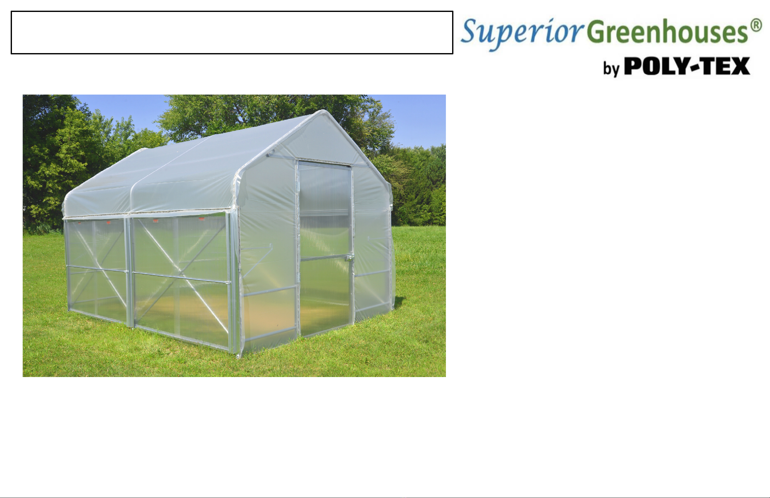
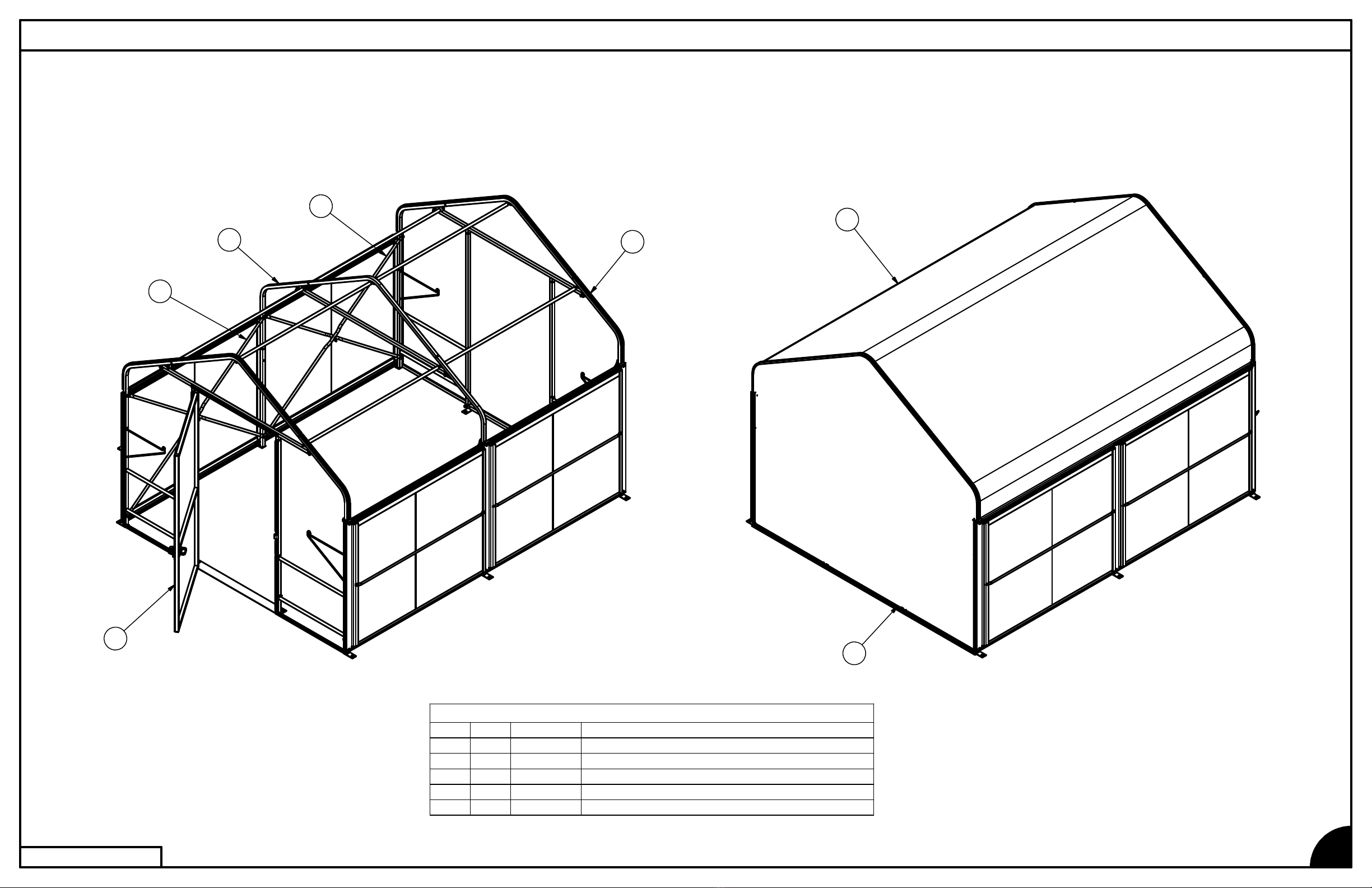
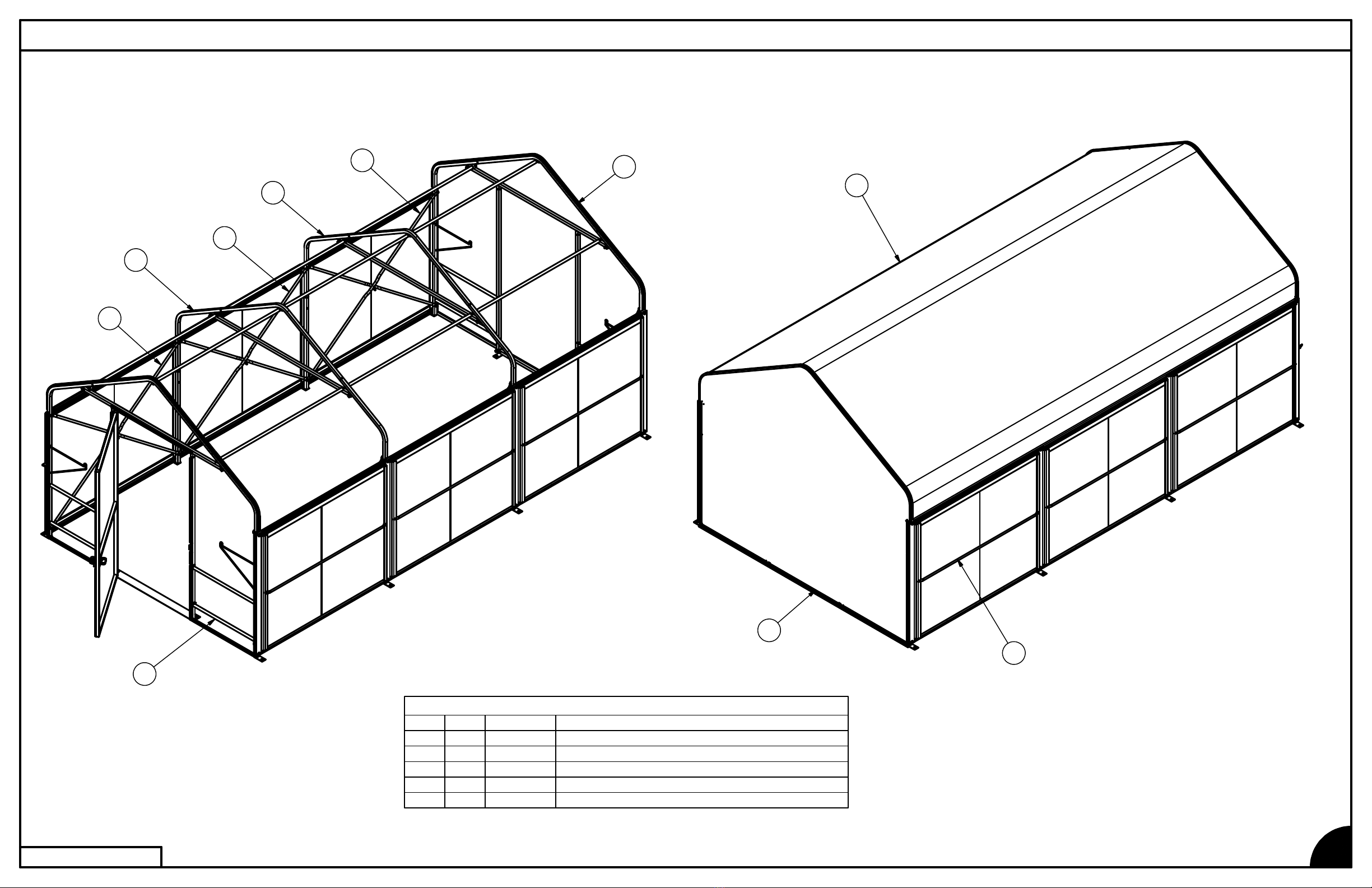
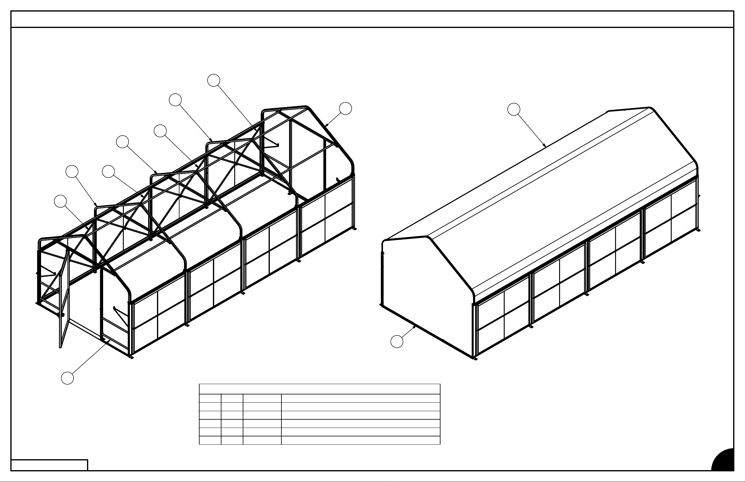
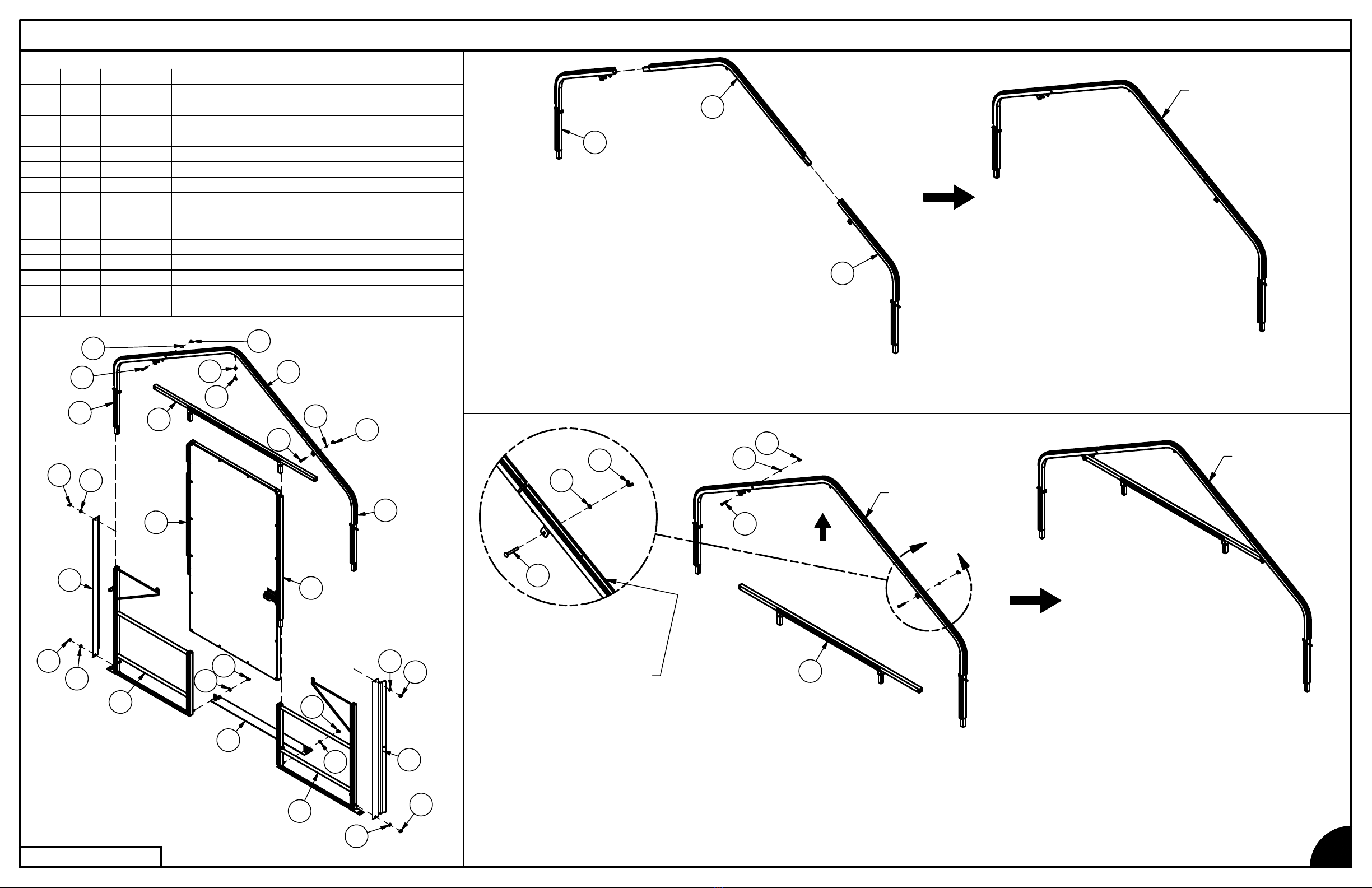
Overview of assembly procedure
While each structure and site is unique, and may require special considerations, these
instructions are for a tilt-up method (where frames are assembled on the ground and tilted
onto ground stakes or anchor rods using ropes or lifts). If installer is not confident to erect the
structure, Poly-Tex suggests hiring a general contractor, carpenter, or similar licensed
business familiar with construction, to assemble and erect the structure.
Do not overload structure. Consult with a Poly-Tex representative prior to adding any
amount of weight over the specified capacity of this structure. Basket purlins, shelving or any
objects of significant weight shall not be hung, attached, or secured to roof or truss members
in a manner that will overload the structure.
Do not walk on polycarbonate sheets. If structure is to be covered with polycarbonate
sheets, always use scaffolding for the erection process to avoid damage to sheeting and to
ensure safety. Polycarbonate sheeting has UV coating protected with vinyl film on the exterior
surface. Install sheets with the film intact and toward the exterior. Remove film once the
sheet has been fastened in place.
2
Limited Warranty
Poly-Tex, Inc. warrants its products to be free from defects in material and
workmanship for a period of (1) year from date of invoice. This warranty is
provided to the original purchaser of the product and is not transferable.
Poly-Tex does not warrant parts not manufactured by Poly-Tex, but does
assign any transferable manufacturer or supplier warranties. Should any
defect be found, full repair or replacement will be rendered to the customer at
no cost following inspection by a Poly-Tex representative and the return of the
defective product to our Castle Rock, MN facility. Expenses for removal or
reinstallation of defective products will not be covered by the warranty.
Non-code compliance or non-engineered structures purchased by our
customers are done so at the customer's own risk. Customers shall indemnify
Poly-Tex from any liabilities or cost for structural failure or any legal action
taken by governing agencies against purchases of non-code compliance
structures. Failure to comply with proper installation or any modifications
to the product will void warranty.
Purchaser will indemnify and hold Poly-Tex and its officers and
agents harmless (to the extent provided by law) from and against all loss,
liability, cost, damage or expense incident to any claim, action or proceeding
against Poly-Tex arising out of the installation, maintenance, use or operation
of the products by purchaser.
POLY-TEX SHALL NOT BE HELD RESPONSIBLE FOR ANY SPECIAL OR
CONSEQUENTIAL DAMAGES, OR FOR ANY DELAY IN PERFORMANCE
OF THIS WARRANTY BEYOND OUR CONTROL. THIS WARRANTY IS
EXCLUSIVE AND IN LIEU OF ALL OTHER WARRANTIES WHETHER
IMPLIED, WRITTEN OR ORAL INCLUDING THE WARRANTIES OF
MERCHANTABILITY AND FITNESS FOR A PARTICULAR PURPOSE.
This warranty does not cover damage from customer abuse, misuse, improper
installation, customer modifications, customer negligence in performing normal
maintenance or damage resulting from acts of nature.
LIMITED WARRANTY
REV: AE-201007

EZ5006 - SUPERIOR 10 x 6 w/ CLEAR ROOF, CLEAR ENDS, ONE DOOR
BILL OF MATERIALS EZ5006
3
REV: AE-201007
BILL OF MATERIALS
DESCRIPTIONITEM CODEQTY
ID
END PKG, DOOR, EZ
EZ201111
END PKG, NO DOOR, EZEZ201212
FRAME CONNECTOR PKG, EZ
EZ201413
COVER PKG, EZ
EZ201514
4
2
1
3

EZ5012 - SUPERIOR 10 x 12 w/ CLEAR ROOF, CLEAR ENDS, ONE DOOR
BILL OF MATERIALS EZ5012
4
REV: AE-201007
BILL OF MATERIALS
DESCRIPTIONITEM CODEQTY
ID
END PKG, DOOR, EZ
EZ201111
END PKG, NO DOOR, EZEZ201212
INTERIOR FRAME PKG, EZ
EZ201313
FRAME CONNECTOR PKG, EZ
EZ201424
COVER PKG, EZEZ20151
5
5
2
2
4
3
4
1

EZ5018 - SUPERIOR 10 x 18 w/ CLEAR ROOF, CLEAR ENDS, ONE DOOR
BILL OF MATERIALS EZ5018
5
REV: AE-201007
BILL OF MATERIALS
DESCRIPTIONITEM CODEQTY
ID
END PKG, DOOR, EZEZ201111
END PKG, NO DOOR, EZ
EZ201212
INTERIOR FRAME PKG, EZ
EZ201323
FRAME CONNECTOR PKG, EZEZ20143
4
COVER PKG, EZ
EZ20151
5
5
2
2
4
3
4
3
4
1
4

EZ5024 - SUPERIOR 10 x 24 w/ CLEAR ROOF, CLEAR ENDS, ONE DOOR
BILL OF MATERIALS EZ5024
6
REV: AE-201007
BILL OF MATERIALS
DESCRIPTIONITEM CODEQTYID
END PKG, DOOR, EZ
EZ201111
END PKG, NO DOOR, EZ
EZ201212
INTERIOR FRAME PKG, EZEZ201333
FRAME CONNECTOR PKG, EZ
EZ201444
COVER PKG, EZ
EZ20151
5
5
2
2
4
3
4
3
43
4
1

EZ5006 EZ5012
EZ5018 EZ5024
ANCHORING LAYOUT
7
REV: AE-201007
1. Prepare a hard level foundation for your product. The product must be
built on a solid level surface in order to perform properly. We recommend
using concrete or wood deck as base.
2. Prepare for assembly of this product by gathering the following tools:
step ladder, rubber mallet, wire cutters, safety glasses, and gloves.
3. Determine the structure model which you have purchased and refer
to the overview on one of the pages 3-6.
4. Open the packaging and sort components by the bill of materials for
each of the packages EZ2011 - EZ2015. Refer to the bills of materials
on pages 3-6, as some models do not need all the packages.
5. Do not place this structure on a slope that exceeds 3 degrees of slope
without blocking the frames to be within this slope.
6. After assembly, secure the product to the ground surface at the
designated securement locations using suitable anchoring. (Not supplied)
6'-0"
3'-2 7/8"
3'-8 1/4"
3'-2 7/8"
10'-2"
6'-0" 6'-0"
3'-2 7/8"
3'-8 1/4"
3'-2 7/8"
12'-0"
10'-2"
18'-0"
3'-2 7/8"
3'-8 1/4"
3'-2 7/8"
10'-2"
6'-0" 6'-0" 6'-0"
3'-2 7/8"
3'-8 1/4"
3'-2 7/8"
24'-0"
10'-2"
6'-0" 6'-0" 6'-0" 6'-0"

EZ2011 - END PKG, DOOR, EZ
DETAIL A
BILL OF MATERIALS
DESCRIPTIONITEM CODEQTY
ID
BENCH FRAME, DOOR END, LHEZ100311
BENCH FRAME, DOOR END, RH
EZ100512
THRESHOLD, DOOR
EZ110713
HEADER, DOOREZ11101
4
PEAK, ENDEZ11241
5
PEAK SUPPORT, END, LH
EZ112616
PEAK SUPPORT, END, RHEZ11281
7
JAMB, DOOR, LATCH SIDE
EZ113118
DOOR, PREHUNG, 42.75 x 80, LHREZ113819
END CAP, GM2000GMSA51210
CARRIAGE BOLT, 5/16"x2-1/2", G5
NB1816211
WASHER, LOCK, 5/16" ZPNB1862212
WING NUT, 3/8" ZP
NB1901713
WING NUT, 5/16" ZP
NB1903214
WASHER, FLAT, NYLONNB1923
7
15
A
DOOR FRAME ASSEMBLY EZ2011
8
REV: AE-201007
PEAK
SUBASSEMBLY
1. Assemble Frames on a flat surface in the
following order:
2. Assemble the RH Peak Support (EZ1128),
End Peak (EZ1124) and LH Peak Support
(EZ1126) as shown.
3. Parts may need to be shaken or wiggled
to insert the swaged end of a component
into the receiving part. A moderate tap of
the rubber mallet may also be required to
completely set all insertions.
4. Position the PEAK SUBASSEMBLY, so that the
WIGGLE WIRE BASE is facing up.
5. Attach the Door Header (EZ1110) to the PEAK
SUBASSEMBLY using (2) 5/16" Carriage Bolts (NB1816),
(2) 5/16" Lock Washers (NB1862), and (2) 5/16" Wing Nuts
(NB1903).
3
14
12
11
11
14
12
15
13
4
5
7
10
13
15
13
15
2
1
9
8
10
15
13
15
13
15
13
13
15
6
6
5
7
PEAK / HEADER
SUBASSEMBLY
4
PEAK
SUBASSEMBLY
11
12
14
11
12
14
WIGGLE WIRE BASE
(PREASSEMBLED)

EZ2011 - END PKG, DOOR, EZ
BILL OF MATERIALS
DESCRIPTIONITEM CODEQTY
ID
BENCH FRAME, DOOR END, LHEZ100311
BENCH FRAME, DOOR END, RH
EZ100512
THRESHOLD, DOOR
EZ110713
HEADER, DOOREZ11101
4
PEAK, ENDEZ11241
5
PEAK SUPPORT, END, LH
EZ112616
PEAK SUPPORT, END, RHEZ11281
7
JAMB, DOOR, LATCH SIDE
EZ113118
DOOR, PREHUNG, 42.75 x 80, LHREZ113819
END CAP, GM2000GMSA51210
CARRIAGE BOLT, 5/16"x2-1/2", G5
NB1816211
WASHER, LOCK, 5/16" ZPNB1862212
WING NUT, 3/8" ZP
NB1901713
WING NUT, 5/16" ZP
NB1903214
WASHER, FLAT, NYLONNB1923
7
15
DOOR FRAME ASSEMBLY EZ2011
9
REV: AE-201007
6. Attach the Door (EZ1138), Door Jamb (EZ1131),
& (2) Door End Bench Frames (EZ1003, EZ1005)
to the PEAK / HEADER SUBASSEMBLY. (The
WIGGLE WIRE BASE on the PEAK / HEADER
SUBASSEMBLY should line up with the WIGGLE
WIRE BASE on the Bench Frames (EZ1003, EZ1005).)
7. Attach the Threshold (EZ1107) to the DOOR FRAME
SUBASSEMBLY using (2) Nylon Washers (NB1923)
and (2) 3/8" Wing Nuts (NB1901).
8. Set aside the remaining (2) End Caps (GMSA51), (5)
Nylon Washers (NB1923), and (5) 3/8" Wing Nuts
(NB1901) for now.
14
6
13
15
13
13
15
13
15
13 15
10 8
9
1
2
15
15
13
10
7
5
4
13
15
12
11
11
12
14
3
PEAK / HEADER
SUBASSEMBLY
8
9
2
1
DOOR FRAME
SUBASSEMBLY
13
15
10
10
15
13
15
13
15
13
15
13
15 13
15
13
3
DOOR FRAME
SUBASSEMBLY

EZ2013 - INTERIOR FRAME PKG, EZ
BILL OF MATERIALS
DESCRIPTIONITEM CODEQTY
ID
DIVIDER, GM2000GMSA5021
PEAK, INTERIOR
EZ112212
WING NUT, 3/8" ZP
NB1901
5
3
WASHER, FLAT, NYLONNB1923
54
LOWER FRAME INTERMEDIATE
EZ10082
5
TUBE, 1.250 SQ x 14GA, 79 IN
EZ11031
7
WLDMT, PEAK SUPPORT, ENDEZ111928
CARRIAGE BOLT, 5/16"x2-1/2", G5
NB181629
WING NUT, 5/16" ZPNB1903210
WASHER, LOCK, 5/16" ZPNB1862211
INTERIOR FRAME ASSEMBLY EZ2013 (FOR ALL SIZES 10' X 12' AND GREATER)
10
REV: AE-201007
8
2
7
5
5
1
3
4
3
4
9
11
10
4
3
9
11
10
8
4
3
1
4
3
1. Assemble (2) Peak Supports (EZ1119), Interior Peak
(EZ1122), and Tube (EZ1103) as shown.
2. Set aside the remaining (2) Dividers (GMSA50),
(5) Nylon Washers (NB1923), and (5) 3/8" Wing Nuts
(NB1901) for now.
5
8
7
5
8
2
9
9
11
10
11
10
1
4
3
4
3
1
4
3
4
3
INTERMEDIATE
FRAME
SUBASSEMBLY
INTERMEDIATE
FRAME
SUBASSEMBLY

EZ2012 - END PKG, NO DOOR, EZ
DETAIL B
BILL OF MATERIALS
DESCRIPTIONITEM CODEQTY
ID
BENCH FRAME, REAR END, LHEZ100411
BENCH FRAME, REAR END, RH
EZ100612
TUBE, 1.250 SQ x 14GA, 55.5 IN
EZ110123
WLDMT, HEADER, 79 INEZ11041
4
REAR BASE
EZ111415
PEAK, ENDEZ112416
PEAK SUPPORT, END, LHEZ11261
7
PEAK SUPPORT, END, RH
EZ112818
END CAP, GM2000GMSA51
29
CARRIAGE BOLT, 5/16"x2-1/2", G5NB1816210
WASHER, LOCK, 5/16" ZP
NB1862211
WING NUT, 3/8" ZP
NB1901
7
12
WING NUT, 5/16" ZPNB1903213
WASHER, FLAT, NYLON
NB1923714
B
END FRAME ASSEMBLY EZ2012
11
REV: AE-201007
13
11 10
12
14
9
14
12
14
12
3
3
13
11
10
6
7
8
4
1
2
12
14
14
12
12
14
9
12
14
5
1. Assemble the RH Peak Support (EZ1128),
End Peak (EZ1124), and LH Peak Support
(EZ1126) as shown.
8
6
7
2. Position the PEAK SUBASSEMBLY, so that the
WIGGLE WIRE BASE is facing away from you.
3. Attach the Header (EZ1104) to the PEAK
SUBASSEMBLY using (2) 5/16" Carriage Bolts
(NB1816), (2) 5/16" Lock Washers (NB1862), and
(2) 5/16" Wing Nuts (NB1903).
13
11
10
4
10
13
11
PEAK
SUBASSEMBLY
PEAK
SUBASSEMBLY
PEAK / HEADER
SUBASSEMBLY
WIGGLE WIRE BASE
(PREASSEMBLED)

EZ2012 - END PKG, NO DOOR, EZ
BILL OF MATERIALS
DESCRIPTIONITEM CODEQTY
ID
BENCH FRAME, REAR END, LHEZ100411
BENCH FRAME, REAR END, RH
EZ100612
TUBE, 1.250 SQ x 14GA, 55.5 IN
EZ110123
WLDMT, HEADER, 79 INEZ11041
4
REAR BASE
EZ11141
5
PEAK, ENDEZ112416
PEAK SUPPORT, END, LHEZ11261
7
PEAK SUPPORT, END, RH
EZ112818
END CAP, GM2000GMSA5129
CARRIAGE BOLT, 5/16"x2-1/2", G5NB1816210
WASHER, LOCK, 5/16" ZP
NB1862211
WING NUT, 3/8" ZPNB1901
7
12
WING NUT, 5/16" ZP
NB1903213
WASHER, FLAT, NYLON
NB1923
7
14
END FRAME ASSEMBLY EZ2012
12
REV: AE-201007
8
5
14
12
9
14
12
12 14
14
12
2
1
4
7
6
10
11
13
3
3
12
14
12 14
9
14
12
10
11
13
4. Attach the (2) End Frame Tubes (EZ1101) & (2) End
Bench Frames (EZ1004, EZ1006), to the PEAK /
HEADER SUBASSEMBLY. (The WIGGLE WIRE BASE
on the PEAK / HEADER SUBASSEMBLY should line up
with the WIGGLE WIRE BASE on the Bench Frames
(EZ1004, EZ1006).
5. Attach the Rear Base (EZ1114) to the END FRAME
SUBASSEMBLY using (2) Nylon Washers (NB1923)
and (2) 3/8" Wing Nuts (NB1901).
6. Set aside the remaining (2) End Caps (GMSA51), (5)
Nylon Washers (NB1923), and (5) 3/8" Wing Nuts (NB1901)
for now.
2
3
3
PEAK / HEADER
SUBASSEMBLY
1
END FRAME
SUBASSEMBLY
END FRAME
SUBASSEMBLY
12
12
14 5
12
14
12
12
14
14 12
14
12
9
14
9
14
END FRAME
SUBASSEMBLY

EZ2014 - FRAME CONNECTOR PKG, EZ
BILL OF MATERIALS
DESCRIPTIONITEM CODEQTY
ID
X-BRACEEZ1100
4
1
PURLIN, BASKET, 73 1/2"GM4000
32
SLIDE BAR, GM 2000GMSA52
23
ASSY, S.A. BOTTOM RAIL, 74"SA40132
4
ASSY, S.A. TOP RAIL, 74" (BROWN)SA4018
2
5
3'-0" x 55 1/4" 8MM CLR PCSSSS1005
46
CARRIAGE BOLT, 1/4"x 3/4", G5NB1820
47
WASHER, LOCK, 1/4" ZP
NB186048
WING NUT, 1/4" ZPNB190249
SNAPPER PIN, .250" x 2.25"NB1996210
CONNECTING THE FRAMES
13
REV: AE-201007
1. Raise the DOOR FRAME SUBASSEMBLY into upright
position and open the door to use as a 'kick stand'.
3
9
9
1
9
8
7
9
8
7
6
6
5
4
8
7
1
1
5
4
6
6
2
2
7
10
8
1
3
2
2. Raise INTERMEDIATE FRAME ASSEMBLY into
upright position and attach (2) Purlins (GM4000)
to connect the two frames as shown.
(Note: for an EZ5006 10' x 6' structure, your 2nd
and final frame will be an END FRAME ASSEMBLY.)
2
2
DOOR FRAME
SUBASSEMBLY
INTERMEDIATE
FRAME
SUBASSEMBLY

EZ2014 - FRAME CONNECTOR PKG, EZ
DETAIL C
(2 PLACES)
BILL OF MATERIALS
DESCRIPTIONITEM CODEQTY
ID
X-BRACEEZ1100
4
1
PURLIN, BASKET, 73 1/2"GM4000
32
SLIDE BAR, GM 2000GMSA52
23
ASSY, S.A. BOTTOM RAIL, 74"SA40132
4
ASSY, S.A. TOP RAIL, 74" (BROWN)SA4018
2
5
3'-0" x 55 1/4" 8MM CLR PCSSSS1005
46
CARRIAGE BOLT, 1/4"x 3/4", G5NB1820
47
WASHER, LOCK, 1/4" ZP
NB186048
WING NUT, 1/4" ZPNB190249
SNAPPER PIN, .250" x 2.25"NB1996210
C
CONNECTING THE FRAMES
14
REV: AE-201007
1
1
2
6
3
1
1
8
10
7
2
2
6
6
4
5
1
1
7
8
4
5
6
78
9
7
8
9
9
93
1
1
10
3. Install (2) X-Braces (EZ1100) on each interior side of
structure by alternately twisting braces into place onto
the hooks as shown.
4. Connect each pair of X-Braces (EZ1100) with a Snapper
Pin (NB1996) as shown.
5. Repeat steps 2 - 4 for each additional INTERMEDIATE
FRAME ASSEMBLY and END FRAME ASSEMBLY.
DOOR FRAME
SUBASSEMBLY
INTERMEDIATE
FRAME
SUBASSEMBLY
END FRAME
SUBASSEMBLY

EZ2014 - FRAME CONNECTOR PKG, EZ
DETAIL R
BILL OF MATERIALS
DESCRIPTIONITEM CODEQTY
ID
X-BRACEEZ1100
4
1
PURLIN, BASKET, 73 1/2"GM4000
32
SLIDE BAR, GM 2000GMSA52
23
ASSY, S.A. BOTTOM RAIL, 74"SA40132
4
ASSY, S.A. TOP RAIL, 74" (BROWN)SA4018
2
5
3'-0" x 55 1/4" 8MM CLR PCSSSS1005
46
CARRIAGE BOLT, 1/4"x 3/4", G5NB1820
47
WASHER, LOCK, 1/4" ZP
NB186048
WING NUT, 1/4" ZPNB190249
SNAPPER PIN, .250" x 2.25"NB1996210
CONNECTING THE FRAMES
15
REV: AE-201007
R
3
9
9
9
8
7
9
8
7
6
5
4
8
7
1
1
5
4
6
6
2
2
7
10
8
1
1
3
6
2
6. Attach roof Purlins (GM4000) to Frame
Subassemblies using a Nylon Washer (NB1923)
and 3/8" Wing Nut (NB1901), saved from previous
assembly step, for each Frame Subassembly as shown.
Nylon Washer (NB1923)
from Frame Subassemblies
3/8" Wing Nut (NB1901)
from Frame Subassemblies

EZ2014 - FRAME CONNECTOR PKG, EZ
DETAIL T
DETAIL U
BILL OF MATERIALS
DESCRIPTIONITEM CODEQTY
ID
X-BRACEEZ1100
4
1
PURLIN, BASKET, 73 1/2"GM4000
32
SLIDE BAR, GM 2000GMSA52
23
ASSY, S.A. BOTTOM RAIL, 74"SA40132
4
ASSY, S.A. TOP RAIL, 74" (BROWN)SA4018
2
5
3'-0" x 55 1/4" 8MM CLR PCSSSS1005
46
CARRIAGE BOLT, 1/4"x 3/4", G5NB1820
47
WASHER, LOCK, 1/4" ZP
NB186048
WING NUT, 1/4" ZPNB190249
SNAPPER PIN, .250" x 2.25"NB1996210
SLIDE SIDE INSTALLATION
16
REV: AE-201007
T
U
2
6
3
1
1
8
10
7
2
2
6
6
4
5
1
1
7
8
4
5
6
78
9
7
8
9
9
93
1. Place the Top and Bottom Slide Side Rails (SA4013 and SA4018)
onto the threaded studs as shown.

EZ2014 - FRAME CONNECTOR PKG, EZ
DETAIL V
DETAIL W
BILL OF MATERIALS
DESCRIPTIONITEM CODEQTY
ID
X-BRACEEZ1100
4
1
PURLIN, BASKET, 73 1/2"GM4000
32
SLIDE BAR, GM 2000GMSA52
23
ASSY, S.A. BOTTOM RAIL, 74"SA40132
4
ASSY, S.A. TOP RAIL, 74" (BROWN)SA4018
2
5
3'-0" x 55 1/4" 8MM CLR PCSSSS1005
46
CARRIAGE BOLT, 1/4"x 3/4", G5NB1820
47
WASHER, LOCK, 1/4" ZP
NB186048
WING NUT, 1/4" ZPNB190249
SNAPPER PIN, .250" x 2.25"NB1996210
SLIDE SIDE INSTALLATION
17
REV: AE-201007
V
W
3
9
9
9
8
7
9
8
7
6
5
4
8
7
1
1
5
4
6
6
2
2
7
10
8
1
1
3
6
2
2. Place the End Caps (GMSA51) and Dividers (GMSA50)
from previous assembly step onto the threaded studs for
each Frame Subassembly as shown.
3. Secure each End Cap and Slide Side Divider using a
Nylon Washer (NB1923) and 3/8" Wing Nut (NB1901),
saved from previous assembly step, for each
Frame Subassembly as shown.
Nylon Washer (NB1923)
from Frame Subassemblies
3/8" Wing Nut (NB1901)
from Frame Subassemblies
Nylon Washer (NB1923)
from Frame Subassemblies
3/8" Wing Nut (NB1901)
from Frame Subassemblies
End Cap (GMSA51)
from Frame Subassemblies
Divider (GMSA50)
from Frame Subassemblies

EZ2014 - FRAME CONNECTOR PKG, EZ
DETAIL Y
BILL OF MATERIALS
DESCRIPTIONITEM CODEQTY
ID
X-BRACEEZ1100
4
1
PURLIN, BASKET, 73 1/2"GM4000
32
SLIDE BAR, GM 2000GMSA52
23
ASSY, S.A. BOTTOM RAIL, 74"SA40132
4
ASSY, S.A. TOP RAIL, 74" (BROWN)SA4018
2
5
3'-0" x 55 1/4" 8MM CLR PCSSSS1005
46
CARRIAGE BOLT, 1/4"x 3/4", G5NB1820
47
WASHER, LOCK, 1/4" ZP
NB186048
WING NUT, 1/4" ZPNB190249
SNAPPER PIN, .250" x 2.25"NB1996210
SLIDE SIDE INSTALLATION
18
REV: AE-201007
Y
2
6
3
1
1
8
10
7
2
2
6
6
4
5
1
1
7
8
4
5
6
78
9
7
8
9
9
93
4. Remove the protective film from the Clear Polycarbonate Panels (SS1005) and be certain to install the Panels with the
UV protective (blue) side to the outside of the structure.
5. Set the Panels into the Bottom Rail and bend the middle outward until the panel is short enough to insert into the Top Rail.
6. Slide the Panels toward the center of the opening and attach the Slide Bars (GMSA52) to the End Caps (GMSA51) and
Dividers (GMSA50) using a 1/4" Carriage Bolt (NB1820), 1/4" Lock Washer (NB1860) , and 1/4" Wing Nut (NB1902) at each
Slide Bar end as shown.
7. Secure the structure to the ground surface as shown in the ANCHORING LAYOUT instructions.
1/4" Carriage Bolt
(NB1820)
1/4" Lock Washer
(NB1860) 1/4" Wing Nut
(NB1902)

EZ2015 - COVER PKG, EZ
BILL OF MATERIALS
DESCRIPTIONITEM CODEQTY
ID
10' x 14' CLEAR END POLYBM505221
16' x 26' CLEAR ROOF -24' BM
BM506812
END FRAME POLY INSTALLATION
19
REV: AE-201007
1
1
1. Lay out Wiggle Wire pieces at the base of the end frames. Unroll End Poly Sheets (BM5052) near each end frame. Center the poly in
front of the frame.
2. Using the edge of an End Poly Sheet to act as a guide, leave a surplus of 2" of material and begin installing poly and Wiggle Wire at the
base on one corner using an up and down motion to install the wire over the layer of poly into the wiggle wire base. Proceed
across to the opposite corner, skipping over the door, if present.
3. Lift the poly to the top of the end frame, tension the poly, and attach the first piece of wiggle wire over the peak of the frame.
Continuing to tension the poly, install Wiggle Wire to secure the poly to each side of the roof end.
4. Proceed to install the poly on the other end of the structure. Clip the surplus Wiggle Wire at the corners with wire cutters.
5. Trim poly around door and at perimeter, leaving a minimum of 1" extra material for future tensioning.
2
Wiggle Wire

EZ2015 - COVER PKG, EZ
BILL OF MATERIALS
DESCRIPTIONITEM CODEQTY
ID
10' x 14' CLEAR END POLYBM505221
16' x 26' CLEAR ROOF -24' BM
BM506812
ROOF POLY INSTALLATION
20
REV: AE-201007
HELPFUL HINT: If poly covering is installed on a cool day, the poly may expand as the temperature warms causing the film to loosen.
It may be necessary to re-tension the poly again at a later date. Try to select a calm day for installation of the roof poly.
1. Lay out the Wiggle Wire pieces around the perimeter of the structure so that the pieces are handy. Unroll the Roof Poly Sheet (BM5068)
on the ground along the length of the structure. Be sure to have a minimum of one foot of surplus material at each end of the structure
when installing the Roof Poly Sheet. Because one size of cover is provided for several lengths of structure, there may be a piece left
over for other customer uses.
2. Drape the Roof Poly Sheet over the roof and position with even surplus at each side. Begin installing the Wiggle Wire pieces along one
side using an up and down motion to install the wire over the layer of poly into the wiggle wire base. Maintain approximately the same
amount of surplus poly as a guide to attach the poly in a straight pattern.
HELPFUL HINT: For best performance, a second person may tension the poly a few feet ahead of the installer.
3. On the second side of the structure, secure the poly with Wiggle Wire, starting from the middle of the structure and work outward each
way until the side is complete.
4. Beginning at the roof peak, tension and install Wiggle Wire over the peak and down each side of the end frame. Repeat on the other end
frame. Clip the surplus Wiggle Wire at the corners with wire cutters.
2
Wiggle Wire
2
1
1
This manual suits for next models
3
Table of contents
Other Poly-Tex Greenhouse Kit manuals
Popular Greenhouse Kit manuals by other brands

ClearSpan
ClearSpan CL108545 manual

Growing Spaces
Growing Spaces Doorway installation manual

ClearSpan
ClearSpan R020B00002 installation guide

ClearSpan
ClearSpan EZ-Grow Greenhouse manual

Alton
Alton Victorian Internal Shading instruction manual

Palram Applications
Palram Applications Snap & Grow 8x8 instructions