RHINO Premium User manual

Premium
Greenhouses Direct Ltd
www.greenhousesdirect.co.uk
Service department open Monday to Friday 9am - 5.30pm
0344 493 1929
10x10, 10x12, 10x14, 10x16, 10x18, 10x20
Assembly instructions
Rhino Premium 10ft instructions 0721

Rhino Premium 10ft wide
Online video
Go to our YouTube channel: www.youtube.com/user/Rhinogreenhouses
Premium
Please start by watching the Greenhouse delivery and installation video,
this will provide important background information.
QR codes
As you will be in your garden erecting the greenhouse it may well be
that you will nd it easier to watch the videos on a smartphone or
tablet. To help with this, each video has been assigned a QR code.
QR code scanners can be downloaded for free online. Once installed,
simply scan the code with your smartphone or tablet and it will take you
directly to the correct video.
Digitally printed on 120gsm Recycled Evolution paper
Dynamic Print Norwich capture the CO2 emissions from their
paper purchases by planting native woodland, right here in the UK,
through the Woodland Trust and the Woodland Carbon scheme.

10x12
10x14
10x10
10x16
10x20
10x18

R72
R31
R32
R33
R85
R15
R71
R16
R83
R17
R18
R75R74
R86
R05
R79
Part No Description 10x10 10x12 10x14 10x16 10x18 10x20
R93/45 Bayliss XL Autovent Opener 4 6 8 8 10 12
End pack
R05/1 Heavy glazing bar rear size 8 2351mm 2 2 2 2 2 2
R05/3 Heavy glazing bar rear size 6 1928mm 2 2 2 2 2 2
R15/1 2ft Door x member top 614mm 2 2 2 2 2 2
R16/1 2ft Door transom 575mm 4 4 4 4 4 4
R17/4 10’ door track mount 1886mm 1 1 1 1 1 1
R18/3 10’ door track 3088mm 1 1 1 1 1 1
R31/4 Door track support 368mm 2 2 2 2 2 2
R32/41 10’ top stay rear 3068mm 1 1 1 1 1 1
R32/43 10’ top stay front 923mm 4 4 4 4 4 4
R33/2 end stay 1535mm 8 8 8 8 8 8
R33/4 10’ stay roof 2215mm 4 4 4 4 4 4
R71/1 Door post 1993mm 2 2 2 2 2 2
R72/10 Base 10’ end 3160mm 1 1 1 1 1 1
R72/23 Base Flush Door end LH 961mm 1 1 1 1 1 1
R72/24 Base Flush Door end RH 961mm 1 1 1 1 1 1
R74/5 Lower Door guide 10ft wide 1 1 1 1 1 1
R75/3 Ramp 4ft 1238mm 2 2 2 2 2 2
R79/3 Glazing bar ctr front 440mm 2 2 2 2 2 2
R79/4 Glazing bar 1910mm 2 2 2 2 2 2
R83/1 Door stile 1913mm 3 3 3 3 3 3
R85/1 Meeting stile 1913mm 1 1 1 1 1 1
R86/1 Door x member bottom 614mm 2 2 2 2 2 2
R92/9 Glazing Bead long 2347mm 18 18 18 18 18 18
R92/57 Door Wool Pile Classic/Premium Fitted 1 1 1 1 1 1
R92/58 Guide Rail woolpile Fitted 1 1 1 1 1 1
R92/21 Low modulus clear silicone 1 1 1 1 1 1
R93/55 Corner Base Anchor 4 4 4 4 4 4
R92/14 H Section (Above Door) 588mm 3 3 3 3 3 3
R92/64 Guide rail ller strip 926mm 2 2 2 2 2 2
Door xings pack
R90/10 M8 Hexagonal Lock Nuts Stainless Steel 8 8 8 8 8 8
R90/11 M8 nyloc Insert Nuts Stainless Steel 4 4 4 4 4 4
R90/9 M8x25 hex set stainless steel 4 4 4 4 4 4
R91/5 Glazing clips “W” 12 12 12 12 12 12
R92/1 Door wheels 4 4 4 4 4 4
R92/6 Door handle nylon male 2 2 2 2 2 2
R92/7 Door handle nylon female 2 2 2 2 2 2
R94/28 Door stop bracket 2 2 2 2 2 2
R90/46 M6 Flat nut stainless steel 4 4 4 4 4 4
R90/47 M6x8mm Socket button head stainless steel 4 4 4 4 4 4
R90/48 M4x8mm Pozi pan stainless steel 4 4 4 4 4 4
R90/49 Door stop buffer 4 4 4 4 4 4
Plate xings pack
R91/3 Eave plate 4 4 4 4 4 4
R91/4 Ridge plate 2 2 2 2 2 2
R93/56 Zed Bracket 2 2 2 2 2 2
R32/5 staging /hanging bskt cleat 16mm 4 4 4 4 4 4
R93/53 Guide Rail End Cap 2 2 2 2 2 2
R90/40 3.9x9.5mm Pan pozi self tapper stainless steel 4 4 4 4 4 4
Gutter xings pack
R92/25 LH oulet 1 1 1 1 1 1
R92/26 RH oulet 1 1 1 1 1 1
R92/27 LH stopend 1 1 1 1 1 1
R92/28 RH stop end 1 1 1 1 1 1
R92/29 LH downpipe clip 1 1 1 1 1 1
R92/30 RH downpipe clip 1 1 1 1 1 1
R92/31 32mm Bend-45 Degree Black 4 4 4 4 4 4
R90/23 M4 x 12mm hex set stainless steel 2 2 2 2 2 2
R90/24 3.5 x 12mm stainless self tapping screw 2 2 2 2 2 2
R90/3 M4 hex full nut stainless steel 2 2 2 2 2 2 Wrapped together

R32 R33
R21
R08
R34
R24
R04
R23
R72
R79
Part No Description 10x10 10x12 10x14 10x16 10x18 10x20
LP1 Length pack 1
R04/3 ridge 10’ long 3113mm 1
R04/4 ridge 12’ long 3731mm 1
R04/5 ridge 14’ long 4349mm 1
R04/6 ridge 16’ long 4967mm 1
R04/7 ridge 18’ long 5585mm 1
R04/8 ridge 20’ long 6203mm 1
R08/11 hd eave 10’ long 3113mm 2
R08/12 hd eave 12’ long 3731mm 2
R08/13 hd eave 14’ long 4349mm 2
R08/14 hd eave 16’ long 4967mm 2
R08/15 hd eave 18’ long 5585mm 2
R08/16 hd eave 20’ long 6203mm 2
R34/22 10’ hanging basket rail 3050mm 2
R34/23 12’ hanging basket rail 3668mm 2
R34/24 14’ hanging basket rail 4286mm 2
R34/25 16’ hanging basket rail 4904mm 2
R34/26 18’ hanging basket rail 5522mm 2
R34/27 20’ hanging basket rail 6140mm 2
R72/3 Base 10’ side 3121mm 2
R72/4 Base 12’ side 3739mm 2
R72/5 Base 14’ side 4357mm 2
R72/6 Base 16’ side 4975mm 2
R72/7 Base 18’ side 5593mm 2
R72/8 Base 20’ side 6211mm 2
LP2 Length pack 2
R21/1 vent cill 1 bay 597mm 2 2
R21/4 vent cill large cut out 2 bay 1215mm 2 2 4 4 4 6
R23/2 large vent side 960mm 4 8 8 8 12 12
R24/1 Large vent hinge 1bay 630mm 2 2
R24/2 Large vent hinge 2 bay 1248mm 2 2 4 4 4 6
R32/7 vent crossbar 1 bay LARGE (87 degree) 634mm 4 6 8 8 10 12
R33/1 side/roof stay 1606mm 4 4 4 4 4 4
R79/7 Large vent glazing bar 960mm 2 2 4 4 4 6
R91/1 M8 ‘J’ Bolt 9 9 11 11 11 13
R91/6 Tie rod Brackets 2 2 4 4 4 6
R92/12 glazing rubber 124 136 148 160 172 184
R92/16 H section glass joint 13 13 13 13 13 13
R92/17 H section glass joint 10/12ft roof 6 6 6 8 8 8
R92/35 32mm outlet pipe 1 metre Black 2 2 2 2 2 2
R92/46 Louvre Glass Seal Strip 558mm 8 8 10 10 12 12
R93/2 Louvre 5 blade frame 460mm 4 4 5 5 6 6
Anchor xings pack
R90/15 M8 Full Nut Stainless Steel 22 22 30 30 30 38
R90/16 M8 at washer stainless steel 22 22 30 30 30 38
R91/20 6 x 75 HEX FLANGE ANKERBOLT ZINC 9 9 11 11 11 13
R93/54 Base Anchor 5 5 7 7 7 9
Nut and bolt xings pack
R90/19 M6 x 11 bolt High Tensile 430 450 470 490 500 520
R90/2 M6x22 Cruciform Head Aluminium Screws 2 2 2 2 10 2
R90/20 M6 Nut High Tensile 436 456 476 496 506 526
R90/22 M3 x 8mm bolt Stainless st 8 8 16 16 16 24
R90/38 M3 nyloc inserts stainless steel 8 8 16 16 16 24
Vent and louvre xings pack
R90/5 M6x11 cropped head aluminium 2 4 4 4 6 6
R91/17 Large window lock L/H 2 3 4 4 6 6
R91/22 Large window lock R/H 1
R92/49 Louvre End Cap 16 16 20 20 24 24
R92/55 Roof Vent Stops 4 8 8 8 12 12
R92/7 Door handle nylon female 2 4 4 4 6 6

R34
R05
R07
R05
R07
Part No Description 10x10 10x12 10x14 10x16 10x18 10x20
RP Roof pack
R05/10 Heavy glazing bar, 10’ roof 1866mm 8 10 12 14 16 18
R07/13 10’ corner roof LH 1866mm 2 2 2 2 2 2
R07/14 10’ corner roof RH 1866mm 2 2 2 2 2 2
R91/7 Tie rod 1800mm 1 1 2 2 2 3
R92/45 glazing bead 10ft roof 1924mm 25 29 33 37 41 45
SP Side pack
R05/2 Heavy glazing bar size 1 1492mm 8 10 12 14 16 18
R07/1 corner side LH 1492mm 2 2 2 2 2 2
R07/2 corner side RH 1492mm 2 2 2 2 2 2
R34/20 Eave brace 360mm 8 10 12 14 16 18
R34/21 Ridge brace 680mm 4 5 6 7 8 9
R92/8 Glazing beads medium 1489mm 25 29 33 37 41 45
Glass
RG/A 295x405 Glass A 295x405 2 2 2 2 2 2
RG/B 605x972 Glass B 605x972 10 12 14 16 18 20
RG/C 605x1502 Glass C 605x1502 13 15 16 18 19 21
RG/E 605x610 Glass E 605x610 4 4 4 4 4 4
RG/F 605x421 Glass F 605x421 3 3 3 3 3 3
RG/G 605x903 Glass G 605x903 14 12 14 16 18 20
RG/K 605x512 Glass K 605x512 2 2 2 2 2 2
RG/L 542x100 Glass L 542x100 20 20 25 25 30 30
RG/N Apex Glass N Apex 2 2 2 2 2 2
RG/R 605x848 Glass R 605x848 4 4 5 5 6 6
RG/S Triangle Shape Glass S Triangle Shape 8 8 8 8 8 8
RG/T 605x192 Glass T 605x192 4 4 5 5 6 6
RG/V 605x410 Glass V 605x410 2 2 2 2 2 2
RG/Z 295x1502 Glass Z 295x1502 2 2 2 2 2 2

Please note: Drawings are not shown to scale
You will need the following:
Someone to assist you
Sturdy stepladder
10mm spanner
10mm nut driver
13mm spanner
Hacksaw-preferably small
Tape measure
Skeleton gun for silicone
Spirit level
Drill (drill bits HSS 4.5 & 7mm. Masonry 6mm)
plus a few common tools
Bags of readymix for the anchors if erecting
on a soil site
In addition there are a few tools which are
useful but not essential:
Glass sucker (for handling and adjusting the
large panes of glass) a rubber mallet and a
glazing paddle
These, more specialist tools, are available from
Greenhouses Direct if you wish to buy them.
Thoughts & considerations
Where you choose to site your greenhouse will
usually be dictated by the design of your garden
and personal choice so we will conne ourselves
to considering the different types of ground that
it is built on. Rhinos can be sited on either soil or a
hardstanding. Either way the main requirements
are that the greenhouse is erected both square
& level.
Soil bases are perfect provided that the soil is
compactedsothatitdoesn’tsubsideorgetwashed
away, avoid freshly dug soil for this reason. If
siting on a lawn we would recommend that the
turf is cleared from an area at least 300mm (1ft)
greater than the size of the greenhouse - you
won’t want grass inside and this will allow an
edge to mow over rather than cut right up to the
greenhouse base.
General Points
before you start
1st of 6 pages
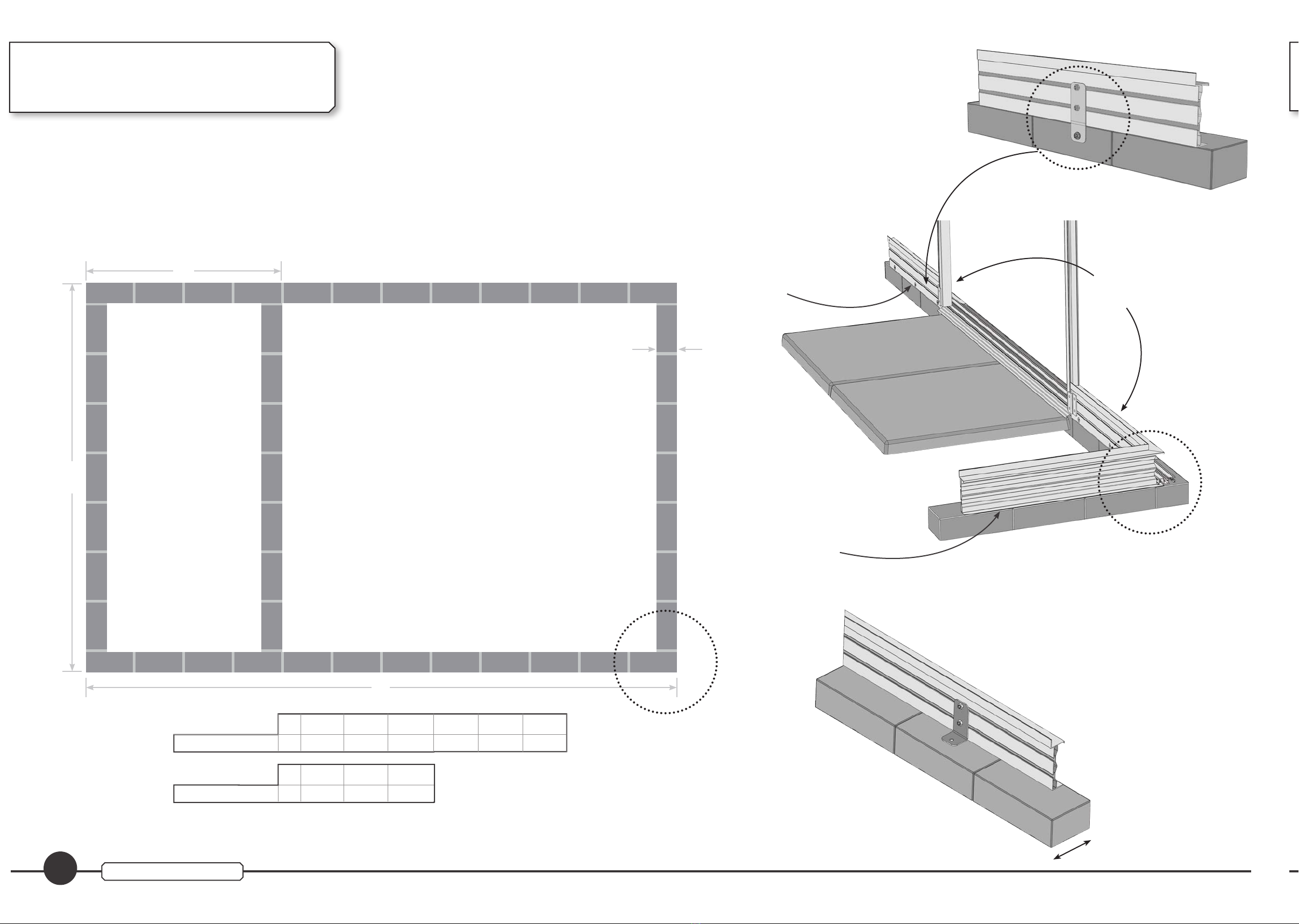
Rhinos all include integral aluminium bases
which sit directly onto the soil and have sturdy
ground anchors which can be concreted in to
the ground at strategic points. The concreting is
done last of all once the greenhouse is glazed.
Hardstanding bases are no problem for the
Rhino as the integral base has a wide lip.
Brick plinth bases are perfect for the Rhino,
but please make sure you study the specic
base plan on page 4.
Please also consider the following points:
Is the site level?
If not nd some means of packing underneath
the aluminium base it must be level.
Is the area likely to ood?
Water on the outside of an oversize concrete pad
is likely to make its way under the aluminium
base and settle inside the greenhouse unless
steps are taken to seal the base or drain the
water away.
How will you x it down?
Please see the next page
Proximity to fences, buildings etc
If at all possible leave adequate room all round
the Rhino to ease initial construction and any
subsequent maintenance for the greenhouse
and adjacent walls or fences.
Construction order
It is important to construct the Rhino in the
correct order. You may expect to have to position
the integral base as the rst job but this would
in fact greatly complicate matters later on.
Once again it will help to have read the plans in
advance.
Open & identify the parts
We suggest that you are careful to lay out parts
in an orderly fashion - grouping sections that
are made of the same prole together but in
their different lengths.
Most sections either have a sticker containing
the part number on them or are grouped with
identical sections which include a sticker. This
will help you greatly in identifying the various
parts.
Consider the weather
Erecting a large greenhouse will take more than
a day. Before you start please consider what
steps you will take to protect the greenhouse
if you are leaving it overnight or for a few
days without the frame being fully glazed and
anchored. Even a completely unglazed frame
will need to be anchored down in some way if
there is a possibility of strong winds.
Colour powdercoat nish
The optional powdercoated nish is strong and
durable. Unlike traditional paint nishes it will
not ake and is very resistant to fade. Don’t be
concerned if you notice some areas on a few
proles where the paint is less dense. This is
due to some of the proles being very intricate
with channels & cavities on both sides. The
decision of where the primary and secondary
painting surfaces and jig points are situated is
deliberate. This takes into account how visible
the prole will be on the nished greenhouse.
Caution
The edges of the extrusion can be extremely
sharp. You may wish to consider wearing thin
gloves at certain stages.
During glazing and handling glass we advise
you to wear protective eye goggles.
Handling glass
While you are moving & handling the glass be
aware that the toughening process makes it
vulnerable to knocks on its edges. Catching an
edge on concrete or brickwork whilst carrying it
can easily cause it to break. Of course, when it
is installed in the greenhouse the edges are all
well protected.
Step ladders
Take care when working on your stepladder,
especially when the ground is soft.
Is your level, level?
Thismay sound a daftquestion butit issurprising
how often it crops up. You will have real difculty
erecting your greenhouse if your level is giving
the wrong readings.
Check it before you start:
Try it on a surface you believe to be level, note
the position of the bubble, turn it round (180
degrees) and check that the bubble gives the
same reading. If it doesn’t buy a new one quickly
–you’ve just saved yourself a lot of work!
Introduction
Plan ahead
See page 24 point 12. The roof vents are slid into
the end of the ridge section so enough clearance
must be allowed when siting the greenhouse.
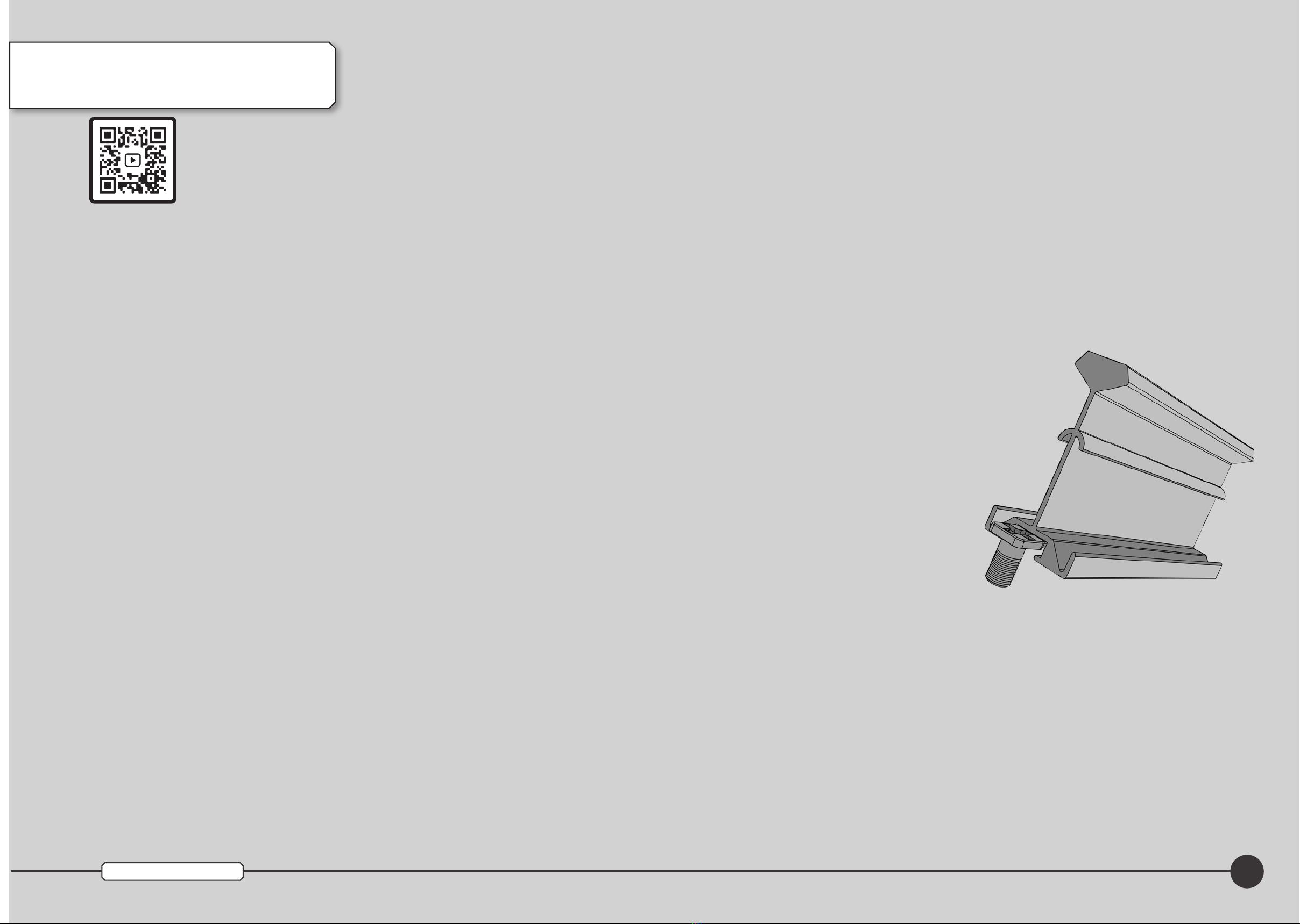
Construction method
The greenhouse is assembled using aluminium
bolts & nuts because they will not rust. These
can be tightened reasonably tight but be careful
not to over-tighten, as being much softer than
steel they will eventually sheer.
PLEASE NOTE! BEFORE USING THESE
FIXINGS IT IS ESSENTIAL THEY ARE
LUBRICATED WITH WD40 OR EQUIVALENT.
The method used mostly in the construction of
your greenhouse is shown below. The head of a
bolt is slid in to the channel in the glazing bar
where it is held captive and cannot turn.
Generally it is best to leave nuts reasonably loose
in the early stages of assembling the frame as it
is possible to tighten them in slightly the wrong
position and then nd that the various parts will
not t together correctly. Certainly where the
bolt is passing through two holes such as at the
eave and ridge plates it is best to leave them
loose. Where the bolt slides in a captive nut
channel such as when tting the glazing bars
you will have to partly tighten the nut so that
the bolt doesn’t slide out.
The instructions will tell you when to go round
and tighten the bolts.
1
Rhino Premium 10ft wide

Please note: Drawings are not shown to scale
2Rhino Premium 10ft wide
General Points
before you start
2nd of 6 pages
This section describes the anchor system
and will be referred to later in the
instructions.
The Rhino is very strong but to resist being
blown over in high winds it must be anchored
rmly to the ground. The ground anchors are
made from stainless steel. They not only provide
a secure anchor point but also add rigidity to the
base. There are two types of anchors.
The number and location of the ground anchors
will depend upon the size of Rhino you have
ordered. Please refer to the plans on page 6 for
more details.
Method
The ground anchors x to the frame as shown
here. Note that you will need to slide bolts along
the nut channels in the base to the correct
position.
Fitting onto soil
Dig a good hole under each ground anchor. The
exact dimensions of the hole will depend on
ground conditions but approx 6” x 6”wide x 10”
deep (150mm x 150 x 250 deep) will usually
sufce.
Fit one of the “J” bolts to the anchor (with 2xM8
washers & 2xM8 nuts) and leave it hanging
in the hole until the instructions indicate you
should concrete it into position. Note that
this will be after glazing has been completed,
thereby allowing any adjustments to be made
to the frame.
Ground
anchors on a
soil site
Check & tick before moving on...
Do not x the anchors down until told to
do so, later in the instructions!!!
Base anchor Base corner
anchor
Fitting onto concrete
The base on a Rhino is ideally suited to xing onto
a hardstanding because it is well balanced with
the wide at bottom section.
Concrete pads are not always dead level and it
may be that the base will need packing to even
out any undulations. The base of the greenhouse
must be tted level.
The Ground Anchors are tted in the same way as
described in the previous section but note that the
“J” bolts are not used in this instance.
Drill into the concrete through the hole in the
ground anchor using a 6mm masonry drill bit.
Fix down using the special concrete screws as
provided. These screws are tightened directly in
to the hole, no rawl plugs are required. Again,
be sure not to x the base down until indicated
in the instructions.
Fitting onto paving slabs
Whilst a well laid paving slabbed area is ideal as
a location for a Rhino, please be aware of the
following.
Let us assume that your size of Rhino has 9
Ground Anchors supplied and that you screw all
of these down to the slabs. All that has been
achieved is that the Rhino has 9 slabs added
to the weight of it, not the whole concrete
slabbed area. In sheltered situations this may
be adequate as it is likely to be sufcient to
prevent the greenhouse being blown sideways.
In a windy location we would recommend lifting
the slabs where the anchors are positioned and
xing it as described in the section “Fitting onto
soil.” You could make good with the concrete
or by cutting and retting the slabs around the
anchors. This will ensure that the greenhouse is
adequately anchored, bear in mind too, that we
can supply further anchors if needed.
One nal consideration. If you plan to lay slabs
but have not already done so, you could t
the greenhouse onto soil and x it down with
concrete as previously described. You could then
slab all or part of the inside of the greenhouse
once it is installed.
Fitting to brickwork (as in a brick
perimeter wall). Much of what we have written
in the previous section “Fitting onto paving
slabs” applies here.
Note that you are only really xing the greenhouse
to one brick with each ground anchor. You
may wish to order additional anchors for this
arrangement.
Fitting onto brickweave paving
Please see the earlier section “Fitting onto
paving slabs.”
We supply sufcient anchors to suit the vast
majority of locations. If, however you feel that
your particular site warrants extra xings then
please contact our sales department who will
be pleased to assist (Telephone 0344 493 1929

General Points
before you start
3rd of 6 pages
Rhino Premium 10ft wide
Base Footprint
The footprint shown here is the point of contact between the base section and the ground. The
most common installation method is for the greenhouse to be sited on rm soil and for the ground
Anchors (supplied) to be concreted into the soil after the greenhouse has been glazed. The location
of the anchors varies according to the model.
Path Path
35
28
118.00
20.00
66.00
28.00
3160
652
928
1580
32.00mm
A
B
118.00
20.00
66.00
961
1238
961
32.00mm
Rear end Partition Door end
Width
Length
Please ensure that 32.00mm is added to
the overall base length to accommodate
the door ramp.
Soil bases
Please note that on completion of your Rhino, the
internal and external ramps must be supported.
The best way to achieve this is to excavate the
soil and lay a path as shown.
Hardstand
The most common hardstand bases are either a
full slab base, or full concrete base.
However if for example you decide on installing
a concrete strip foundation, you must be sure
to make allowances for xing down through
each anchor as shown below. Failing to make
the concrete strip wide enough could result in
the foundation cracking as you drill the anchors
points.
Greenhouses Direct DO NOT RECOMMEND the use of hardcore or hogging as suitable base
materials due to issues surrounding levelling and securing of greenhouse.
3
A
Length mm 12’
3777 14’
4395 16’
5013 18’
5631 20’
6249
Please note, the dimensions below are only required
if you have ordered a partition with your greenhouse.
B
Partition mm 6’
1897 8’
2515 10’
3133

Rhino Premium 10ft wide Please note: Drawings are not shown to scale
General Points
before you start
4th of 6 pages
4
Brick Plinth Base plan
This Base plan must be adhered to allow the
correct installation and subsequently allow for
correct anchoring.
Once the base is built, position the greenhouse
so that the Inside of the front door base is aligned
ush with the inside row of bricks. The sides and
rear base will nish ush with the outside edge
of the bricks. This will ensure that the Anchors
can be tted correctly. See below for full details.
Please note that on completion of your Rhino
the internal ramp must be supported. The best
way to achieve this is to install a path as shown.
Side base tted ush
with the outside edge
of bricks
Path
Front base tted ush
with the inside of the
bricks Front base
View from
the inside
Greenhouses Direct do not recommend the use of hardcore or hogging as suitable base
materials due to issues surrounding levelling and securing of greenhouse. Based on a brick
width of 102mm
102
If opting for this type of
installation, please contact the
service desk on 0344 493 1929
to request 2x modied ground
anchors.
A
3160
B
Rear end Partition Door end
Width
Length
A
Length mm 10’
3195 12’
3813 14’
4431 16’
5049 18’
5667 20’
6285
B
Partition mm 6’
1929 8’
2547 10’
3165

Please note: Drawings are not shown to scale 5
Rhino Premium 10ft wide
General Points
before you start
5th of 6 pages
The next 2 pages describes the layout of
your Rhino and will be referred to later in
the instructions.
Familiarise yourself with the layout of your
Rhino by checking your order/invoice. Your
frame and glass will be packed according to
the specication noted on that document.
Roof vents
Unless specied differently on your
order, your Rhino will have the roof vent
conguration as shown here. There are a
few models where some variation to the
plans is possible, but note that roof vents
will not t in adjacent bays – there must be
at least one bay between vents:
Partition
If you have ordered a partition, draw it’s
position on the plan to act as a reminder
and so that you can refer back to it during
construction.
When you are building the sides, as early as
page 7 you will need to refer to these plans
for the position of the partition.
Louvre vents
Your Rhino will include 5 blade louvres as
standard. The quantity does vary between
sizes.Pleasecheckthepartslisttodetermine
the quantity for your model. Decide where
you want to t them and draw them on the
plan for later reference.
Note: The louvres can not be tted in the
bays shown shaded on the plans on page 6.
Louvres can t singly in bays like this:
Or side by side like this:
Fitting of Louvres in the rear:
Singly
Side by side
Front Rear
C
C Z Z C
N
N
E
E
K
S
S SA A
S
S S
S SV V
E
E
KC C C C
FFF
Glazing plans
C CC CR
T
B BB
G GG
C CC CR
T
C
CC CR
T
C
CR
T
10x12
10x14
10x10
CC CR
T
C
CR
T
10x16
C
CC C R
T
C
CR
T
10x18
C C
CC CR
T
C
CR
T
10x20
C CC
B
G
B
G
B BB
G GG
B
G
B
G
B BB
G GG
B
G
B
G
B
G
B
G
B
G
B BB
G GG
B
G
B
G
B
G
B
G
B
G
B BB
G GG
B
G
B
G
B
G
B
G
B
G
B
G
B BB
G GG
B
G
B
G
B
G
B
G
B
G
B
G
B
G

Please note: Drawings are not shown to scale
6Rhino Premium 10ft wide
Plan ahead
If you have ordered integral shelving for your greenhouse, you should now slide additional xings
in the channels. Please read separate shelving instructions for more details.
If you have ordered extra anchors, draw them in now on the plans so that you can turn back and
refer to this during construction.
Plans showing details of roof
vents, louvre vents & ground
anchors
10x10
10x12
10x14
All Models rear viewFlush Door front view
10x18
10x20
10x16
All Models rear viewFlush Door front view
General Points
before you start
4th of 4 pages
A
A
A
A
A
A
A
A
A
A
A
A
A
A
A
A
A
A
A
A
A
A
A
A
A
A
A
A
A
A
A
A
A
A
A
A
A
A
A
A
A
A
A
A
A
A
A
A
A
A
A
A
A
A
A
A
A
A
A
A
A
A
A
A
A
A
A
A

7
Rhino Premium 10ft wide Please note: Drawings are not shown to scale
Construct the sides
You will need...
Glazing bar R05/2*
Method...
You will make the frame with the outside
face of the frame facing down. For example,
the eave bar will have the gutter part facing
down as will the other parts.
Plan ahead
If you have ordered a partition please
refer to the PARTITION INSTRUCTIONS
packed separately in the Partition box.
You will need to t some partition
parts at this stage.
The at stays have 2 holes approx halfway
along their length. Place them loosely in position
and check that the bottom one of the two holes
aligns with the glazing bar.
Slide extra bolts in the glazing bar channels.
Each bar needs at least one extra bolt for the
attachment of the heavy duty eave brace (point
2 page 14). In addition slide one extra bolt in
each of the end bars for the stay and three
for each louvre side (in the position you have
chosen).
Lay the parts out as shown right then bolt
together. Make sure that the glazing bars are
pushed tight against both the eave and the
base. Fit the ground anchors to the side bases
in the correct places for your model.
If you have a partition, make sure that you t
the partition side corners now. Please note that
you will have been packed less glazing bars
if this is the case. You must also slide a bolt
in to each nut channel of the side bases. See
drawing top right.
This nished side is
from a 10ft model
Bolt the at stay
to the glazing
bar where they
cross using the
bottom of the
two holes.
All 3 nuts on the
stay should be
left loose at this
stage
Adding extra
bolts for
accessories
If you have a
partition 20ft
18ft
16ft
14ft
12ft
10ft
R72/* R05/2* R08/*
* after the part number, either the quantity
or the part length varies with the greenhouse
size – check the parts list for details.
Extra bolts for
partition
Base side 2xR72/*
Side/roof stay 4xR33/1
Eave 2xR08/*
Anchor R93/54*
LP1
LP1/
LP2
RS
LP1
LP1/
LP2
M6x11 bolt R90/19LP1/LP2
LP1/LP2
From the Nut and bolt xings pack
M6 nut R90/20
If you are tting
integral staging
DO NOT t the
side/roof stays.
Check & tick before moving on...
That each glazing bar is pushed tight
against both the eaves and the base.
That you have tightened all nuts except
for those on the stays (R33/1).
That you have slid extra bolts in the
glazing bar channels for the eave braces
and louvres. You will t these later.
That you have tted the ground anchors.
Have you added extra bolts for integral
staging & shelves?
Have you tted your partition corners
(but only if you’ve ordered one).
Have you slid extra bolts in to the side
bases - only if you have a partition
If you are tting integral staging DO
NOT t the side/roof stays.
That you lubricated the M6 nuts and
bolts with WD40/equivalent
Well done! When you have completed both
sides you can move these out of the way and
move on to construct the rear - see the next
section.
BEFORE STARTING - LUBRICATE THE M6
NUTS AND BOLTS WITH WD4O LUBRICANT
OR EQUIVALENT.

8Rhino Premium 10ft wide Please note: Drawings are not shown to scale
Construct the rear
1st of 2 pages
You will need...
Base rear R72/10
Top stay rear 1xR32/41
End stay R33/2
Corner side 1xR07/1 LH
Corner side 1xR07/2 RH
Corner roof 1xR07/13 LH
Corner roof 1xR07/14 RH
Heavy duty 2xR05/1
glazing bar
Heavy duty 2xR05/3
glazing bar
Plan ahead
We have spread this section over 2 pages.
Carefully study the diagrams on this page
before continuing with laying out the rest
of the parts on the next page.
If you have constructed a greenhouse before,
please pay special attention to the drawing on
the right. The corner sections on a Rhino are
tted in a very different manner to other makes.
The eave and ridge pass through slots in the
corner section and bolt on the outside, this
gives the Rhino more rigidity than conventional
greenhouses (this can be seen in the drawing,
top right on page 12).
Just as with the sides you will make the frame
with the outside face of the frame facing down.
You have already used some of these sections so
we will concentrate on the corner section.
This is the corner section.
The drawing above, may look as though you are
viewing the inside face of the corner section.
In fact it is the outside face you are looking at.
You have to get the corner sections the right way round at this early stage so have a look at the
illustration below to make sure you have set them correctly.
Lay the corners this way up when you lay them on the ground to start construction. Refer to the
large drawing on page 7 for the layout.
The ridge & eave plates t
on this side, nuts this side
too.
Method...
Lay the parts out as shown on page 9 then bolt
together. Leave the bolts loose on the eave and
ridge plates.
The corner side proles are cut square at both
ends. The corner roof proles are mitred at one
end. Mind you don’t get them muddled up.
The mitred end ts at the ridge.
Note that the bolt is always on the outside and
the nut on the inside of the frame.
Remember to slide extra bolts to the appropriate
glazing bars if you have chosen to t a louvre
at the rear of the greenhouse or have integral
staging.
The eave plate should
be tted this way up.
The corner roof will t
to these holes.
The corner side will t
to these.
Continued on the next page...
DownDown
Long
side
Short
side
Base corner 2xR93/55
anchors
Ground anchor 1xR93/54
Eave plate 2xR91/3
Ridge plate 1xR91/4
EP
EP
EP
EP
EP
EP
EP
EP
EP
EP
EP
M6x11 bolt R90/19LP1/LP2
LP1/LP2
From the Nut and bolt xings pack
M6 nut R90/20
From the Plate xings pack
EP
LP1/
LP2

Please note: Drawings are not shown to scale 9
Rhino Premium 10ft wide
R07/14 R07/13
R05/3 R05/3
R05/1
R32/41
R33/2 R33/2
R72/9
R07/2 R07/1
Long
side
Fit the corner
anchors R93/55
& leave loose.
Construct the rear
2nd of 2 pages
Eave and ridge
nuts and bolts
*
*
*
Viewed
from
inside
Finally...
When you have constructed the rear frame turn
it over and t 1 nut & bolt in the bolt channels
(six in total) ready for when the sides are all to
be connected together (stage 2 page 12).
Fit these as shown and tighten so that they
stay in place.
Their positions are shown in the main drawing
by this ‘*’ symbol and arrows.
*
That nuts have been left loose and that
you have tted the 6 nuts and bolts at
the ridge and eaves.
All nuts must be tted to the inside of the
frame.
That you have slid extra bolts in the
glazing bar channels for the louvres (if
you are tting in the rear) and for integral
staging.
Check & tick before moving on...
R93/54
Short
side
Viewed
from
outside

10 Rhino Premium 10ft wide Please note: Drawings are not shown to scale
Base Flush Door end LH 1xR72/23
Base Flush Door end RH 1xR72/24
Corner side 1xR07/1 LH
Corner side 1xR07/2 RH
Corner roof 1xR07/13 LH
Corner roof 1xR07/14 RH
Door post 2xR71/1
Glazing bar 2xR79/4
Door track mount 1xR17/4
Top stay front 4xR32/43
Construct the front
1st of 2 pages
You will need...
*
*
*
R07/14 R07/13
R71/1
R17/4
R32/43
R33/2 R33/2
R72/24
R07/2 R07/1
R32/43
R32/43R32/43
R71/1
R79/3
R72/23
R74/5
Glazing bar centre front 2xR79/3
As with the rear build – start by laying
out the parts as shown below, but at this
point do not connect the parts together.
1
1
Before you bolt any parts together refer to page 11.
R93/55 R93/55
R93/56
R93/54
R93/56
R93/54
Long
side
Short
side
Viewed
from
inside
Flush Door Guide 1xR74/5
End stay 4xR33/2
Ground anchor 2xR93/54
Base corner 2xR93/55
anchors
Ramp 2xR75/3
Wool pile (tted) 2xR92/58
R79/4
R79/4
Z Brackets 2xR93/56
Eave plate 2xR91/3
Ridge plate 1xR91/4
Guide rail end cap 2xR93/53
EP
EP
EP
EP
EP
EP
EP
EP
EP
EP
EP
EP
EP
From the Plate xings pack
M6x11 bolt R90/19LP1/LP2
LP1/LP2
From the Nut and bolt xings pack
M6 nut R90/20
Guide rail ller strip R92/64
EP
EP
LP1/
LP2
EP
M6 at nut 4xR90/46EP From the Door xings pack

11
Rhino Premium 10ft wide Please note: Drawings are not shown to scale
2
2
Connect the corner sides, end stays and
base brackets to the base.
Repeat for the other corner.
3
3
Loosely t a nut and bolt into the door
track mount as shown at position below.
7
7
Push the door track
mount on to the glazing
bar and rst door past
making sure that the
bolts slides into the
channels. Push them
fully home and then
tighten the nuts.
Do the same for the
other door post and
glazing bar.
Connect the Ridge Plate R91/3 to the
Roof Corners R07/13 and 14 and leave
these xing loose for the moment.
8
8
9
9
Insert 6 extra
bolts and nuts
to the corners
as shown
below, exactly
as you did on
page 9
Loosely bolt the door track mount to the corner
section at the hole marked below.
Do the same for the opposite end.
Leave both loose at this stage as you will need
some movement in order to t the ridge plate
in task 7.
Start be sliding the two half ramps into the
centre of the guide rail. Loosely connect
the ush door bases as shown below
making sure that the mitres are towards
the outside, and that they are tted hard against
the ramp on both sides. Centralise the guide rail
to the bases and tighten the xings. Next secure
the guide rail end caps using the xings provided.
Lastly clip the ller strip R92/64 into the guide rail
either side of the outer door ramp.
Slide 2 x M6 at nut stainless steel into
each door post (these will be used much
later to connect the door stops), also slide
4
4
4 x M6 x 11 bolt into the door post. Side an extra
M6 x 11 for each additional integral staging (but
only if you have ordered one of these optional
accessories).
Connect the eave plate (refer back to
page 9 if you can’t remember which way
up they go), top stays and end stays
6
6
as shown page 9. Make sure to leave the plate
xings nger tight at this point. Repeat for the
other side.
Connect the ground anchor as shown. Using
the bottom two xings connect the door
posts to the base using the zed bracket.
5
5
Use the next xing up to connect the end stay to
the door post. Repeat for the other side.
Check & tick before moving on...
That nuts have been left loose at the
eave & ridge plates but that everywhere
else they have been tightened.
That you have tted the 6 nuts and bolts
at the ridge and eaves on the outside.
That you have tted the ground anchors.
Have you ordered integral staging? If so
did you t extra bolts in task 4?
That you slid 2xM6 at nut in to each
door post.
x2 M6 at nut
x4 M6 x 11

12 Rhino Premium 10ft wide Please note: Drawings are not shown to scale
Join the four sides
Plan ahead
From now on most jobs will involve
working with the greenhouse in it’s
nal position so if you have not already
prepared and levelled the ground do
so now.
It is helpful to have someone to hold
the sections because the frame will be
quite exible at this stage.
Eave section
Slide the bolts
in the channels
into the slots in
the eave bar and
tighten.
Rear corner side
Check & tick before moving on...
That the nuts have been left loose at the
eave plates.
That you have connected the eave section
to the corners at all 4 corners.
That you have bolted the 4 sides of the
base together tightly and that the mitres
are tting snugly.
Connect the
four sides
You will need...
You don’t need any new parts in this
section but you will need someone to hold
the section upright while you bolt it to the
next side.
Hold the rear end upright, lift the side
into position and slide the eave section
through the gap in the rear frame. This
will be a fairly tight t which is why we
1
1
left the nuts loose at the eave & ridge plates.
The 2 slots in the eave section should be aligned
with the bolt channels in the rear corner frame
(remember that you slid a total of 6 nuts & bolts
in these channels earlier). Loosen 2 of these
and slide the nut & bolt into the slot in the eave
to secure it in position. See top right for more
details.
2
2Note that this drawing is of the outside
of the rear section.
Before trying to connect these 2 sections, study
the end of the eave bar circled here. You will
see that there are 2 slots rather than holes. The
nuts and bolts that you left in the end section
will be loosened & slid into these slots as you
can see in drawing top right.
3
3Bolt the base corner anchors to join
the end and side frames. These can
be tightened.
4
4Repeat steps 1 to 3 for the second side
and then connect the door end in the
same way.

13
Rhino Premium 10ft wide Please note: Drawings are not shown to scale
Fit the ridge & roof bars
Ridge 1xR04/1 to 8*
Heavy glazing bar R05/10*
With the ridge on the ground t nuts
and bolts to each of the holes (with the
exception of the rst two and the last
1
1
two which are used for the roof stays). The nuts
should be on the underside and left very loose.
Position your step ladder on the inside of the
greenhouse just at the point where the ridge
will connect to the door end. It would be really
useful if you could borrow another step ladder
for the other end as your assistant will need to
support this end of the ridge to keep it level for
a few minutes.
2
2The ridge ts to the front and rear
sections in exactly the same way as the
eave bars did in the previous section.
Push the ridge bar through the gap in the corner
roof sections. Secure it by loosening the 2 nuts
& bolts that you slid into these sections when
you constructed the ends, slide them up into the
slot in the ridge and tighten.
Do not tighten the ridge plate at this stage.
The ridge has been pushed
through the corner roof bars &
secured with 2 bolts.
Your greenhouse will now look like this.
Begin tting the roof glazing bars.
Always start with the bars in the centre
as this will take the whip out of the ridge
3
3
– check the number of bolts you need to slide
up the bars, this is detailed later in this section.
The roof layout varies with the size of the
greenhouse. Refer to the diagram to identify
the position of the vents.
Slide the bar onto one of the bolts that you
tted to the ridge in stage 1. It must be
pushed tight against the ridge and the nut
tightened.
Leave the bottom ends loose at this stage and
t all the glazing bars to the ridge.
Refer to the 6 diagrams showing the roof
layout below & select your model.
Slide extra bolts into each glazing bar as
indicated by the number (i.e. slide 5 extra bolts
into the roof glazing bar on the rst bay of a
10x14). These are the EXTRA bolts required so
slide one more bolt into the glazing bar and use
this to attach to the eave section.
The glazing bars must be pushed tight
against the eaves when bolting into
position. If a gap is left between the glazing
bar and the eave then the glass will not t
correctly when the roof is glazed.
Repeat for the other side of the greenhouse.
You will need...
* after the part number = either the
quantity or the part length varies with the
greenhouse size –check the parts list for
details.
20ft
18ft
16ft
14ft
12ft
10ft
6
6
5
5
8
8
4
4
5
5
5
5
8
8
6
6
5
5
6
6
5
5
8
8
8
8
6
6
5
5
6
6
5
5
8
8
4
4
8
10
10
8
6
6
5
5
6
6
5
5
8
8
4
4
5
5
8
8
6
6
5
5
6
6
5
5
8
8
4
4
4
4
8
8
6
6
5
5
Plan ahead
You will be required to slide a
number of EXTRA bolts into the roof
glazing bars during this task so that
they are in position for tting the
braces, hanging basket rails and roof
crossbars. The drawings of the roof
layout will show how many EXTRA
BOLTS you need.
Don’t be too concerned if you get
your sums wrong as it is not difcult
to quickly undo a glazing bar and slip
another bolt in the channel.
If you have ordered a partition
you will be tting the partition roof
corners now. Please also refer to the
separate partition instructions. You now have enough bars xed in place to
begin tting the vent crossbars – please see
the next section.
Have you tted your partition roof
corners, but only if you ordered one.
M6x11 bolt R90/19LP1/LP2
LP1/LP2
From the Nut and bolt xings pack
M6 nut R90/20
RP
LP1
Indicates the position where
you will t the Tie rod and
brackets.

Please note: Drawings are not shown to scale
14 Rhino Premium 10ft wide
Complete the roof Fit the 4 at stay bars diagonally to the
roof. These t to the bottom of the second
glazing bar then at the ridge just in from
the ridge plate. Repeat this at the rear
end.
3
3
Bolt it LOOSELY to the ridge & tighten at the
eave. This may well require some effort as you
will be pulling the building square by tting
these braces then connect the top hole of the
two centre holes to the glazing bar, again leaving
loose.
Vent crossbar R32/7*
This angle section has several cut outs
and holes – see drawing on this page to
help identify it.
Hanging basket rail 4xR34/22 to 27*
Eave brace 360mm long R34/20*
Ridge brace 690mm long R34/21*
10ft Roof stay 4xR33/4
The numbered drawing below, is of the inside of
a Premium 10ft looking up at the roof. It shows
what each of the extra bolts is used for. Different
sized greenhouses will have slightly different
arrangements but the principle is the same.
Fit the eave braces (these are the shorter
of the 2 types of heavy “T” section brace)
to the glazing bars immediately above
2
2
and below the eave section like the ridge braces
their position being set by the bent angle.
Fit the ridge braces (these are the longer
of the 2 types of heavy “T” section brace)
to the glazing bars immediately below
1
1
The simplest way to t the vent crossbars
in the correct position is to take a pane
G (605x903) and place it temporarily in
position (see glazing plan on page 23).
4
4
Make sure that you have the crossbar the right
way up (see drawing below) you will notice that
each end has a cut out which will t around the
side of a glazing bar. Slide each end over the
glazing bar and move it into its approximate
position.
When you have tted all the roof vent crossbars
remove the temporary pane of glass for reasons
of safety.
Fit the 4 hanging basket rail brackets to
the holes in the corner roof sections.
5
5
Check & tick before moving on...
That the nuts have been left loose at the
eave plates & the diagonal braces at the
eave & ridge.
That you have tted all the vent crossbars
(4 or 12) depending on the model and that
the hanging basket rails are bolted tightly.
Bolt the hanging
basket rails to the
brackets & then to
every roof glazing
bar.
You will need...
* after the part number = either the quantity
or the part length varies with the greenhouse
size –check the parts list for details.
5
5
1
1
2
2
3
3
4
4
5
5
the ridge. Start by tting the braces from the
middle out. After tting the rst brace look
along the ridge and check that it is level and
has not bowed downwards - if it has push it up.
When you’re happy that the ridge is perfectly
horizontal t the remaining braces using the
rst brace as a template for the rest.
Bolts in the
roof bars
If the ridge sags then the eaves will bow
outwards at the gutter. It is useful at this
stage to use the tie rods to pull the eaves
6
6
in just a shade (the ridge will then bow upwards
very slightly). When the glass is tted it will
settle back to being level and the eaves straight.
With your assistant, loosely t the threaded M8
Tie Rod to the stainless steel Tie Rod Brackets
leaving plenty of room for adjustment of the
nuts. Fit the brackets to the appropriate glazing
bars as indicated by the arrows on the previous
page.
Your Rhino may have more than one Tie Rod, if
so t them all - see below.
Each end of the tie rod is secured with two M8
nuts and washers, one either side of the tie rod
bracket.
Roof tie rod R91/7
Roof tie rod brackets R91/6
M8 nuts R90/15
M8 washers R90/16
6
6
Partition
Please note the following parts will have been
removed if you have a partition.
2 x R34/20 Eave brace
1 x R34/21 Ridge brace
LP2
LP1
SP
EP
SP
Hanging basket rail bracket 4xR32/5
These 4 parts are 16mm long with 2
slotted holes.
From the Plate xings pack
EP
From the Anchor xings pack
RP
LP2
LP2
Table of contents