3
www.automationdirect.com
1 - 8 0 0 - 6 3 3 - 0 4 0 5
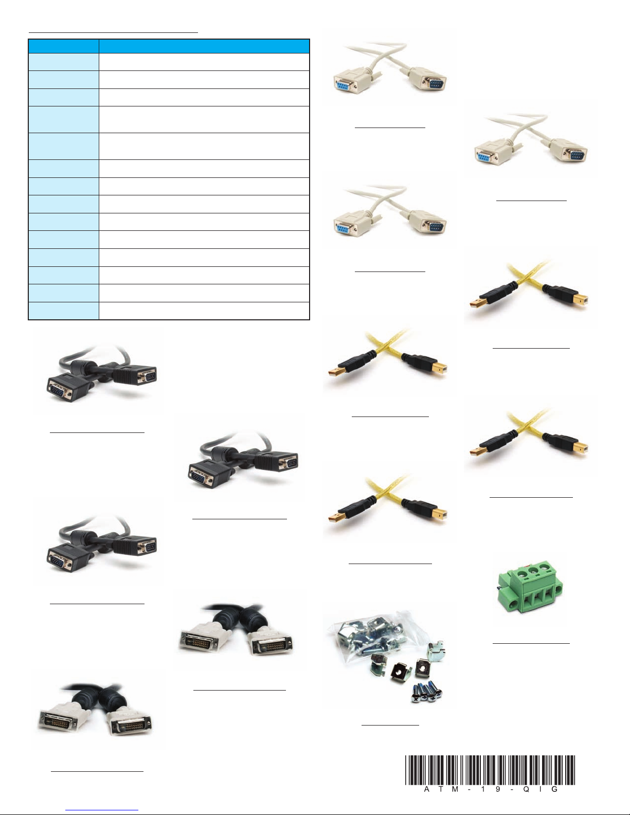
Display Power
Button
Power
Indicator
DISPLAY POWER
WARNING
Touch Screen is still
active while display
power is off
LCD Power Button:
MAIN MENU
BRIGHTNESS/CONTRAST
1280X1024 63.9KHZ/60HZ
COLOR
POSITION
SETUP
EXIT
R G B
OSD Settings Main Menu:
Additional Help and Support
• For product support, speci ications, installation, and
troubleshooting, a Hardware User’s Guide, ATM-19-
USER, is included on the supplied Documentation
and Driver CD, or downloadable rom the Online
Documentation area o the AutomationDirect Web site.
• For additional technical support and questions, call our Technical
Support team 770-844-4200.
NNTTEE::NCE Y U HAVE C NNECTED Y UR PC AND THE M NIT R,
SELECTED THE VIDE S URCE, AND P WERED B TH UNITS, IT IS
SUGGESTED THAT THE “SELECT (AUT ADJ)” BUTT N N THE REAR
F THE M NIT R BE PRESSED T MAXIMIZE THE VIDE SETTINGS.
6. Apply Power to the Monitor & PC
• Press the DISPLAY POWER button on the rear o the monitor to wake the
monitor up. Pressing the DISPLAY POWER button again turns o the
backlight inverter and puts the monitor in a reduced power state but
the touch screen remains active. It is important to note that this switch
does not disconnect power rom the monitor. Power is always supplied
to the internal AC/DC power supply, which in turn continually supplies
power to the internal monitor electronics and the optional touch screen
controller.
7. Install the Appropriate Touch Screen Driver
• Applies to ATM1900T touch screen version only.
• Insert the Documentation and Driver CD into the host PC’s CD drive.
• I the CD does not start automatically with the window shown below
displayed, then go to Start > Run, browse to the CD’s “atlas.exe” ile,
open it, and click OK.
• From the Atlas screen, the user can view the Hardware User’s Guide or
the monitor being used, and/or install the touch screen drivers or the
particular PC operating system being used. Be ore installing the drivers,
please read the Touch Screen Driver Documentation or operating
system details.
• Reboot the PC and restart the monitor to activate the driver.
8. Verify Video and Touch Screen Functionality
• Veri y the monitor’s video display by running a amiliar program.
• I using the touch screen model (ATM1900T), use the touch screen to
navigate by running a amiliar program.
9. Adjust the Monitor OSD Settings as Required
• Press the Select (Auto Adj) control button on the rear o the panel to
initiate an automatic con iguration o the screen.
• Although normally not needed, the control buttons on the rear o panel
can be used to make other adjustments to the screen.
• Consult the Hardware User’s Guide, ATM-19-USER, on the supplied
Documentation and Drive CD or detailed usage o the OSD settings.
10. Installation Complete
WARNING: The monitor does not automatically select a video input
mode. The user must press the “UP (VGA/DVI)” button on the rear
of the monitor to select either VGA or DVI input. If a “No Video”
messa e appears on the screen, it is also su ested the user try usin
the “UP (VGA/DVI)” button to select the active video input.
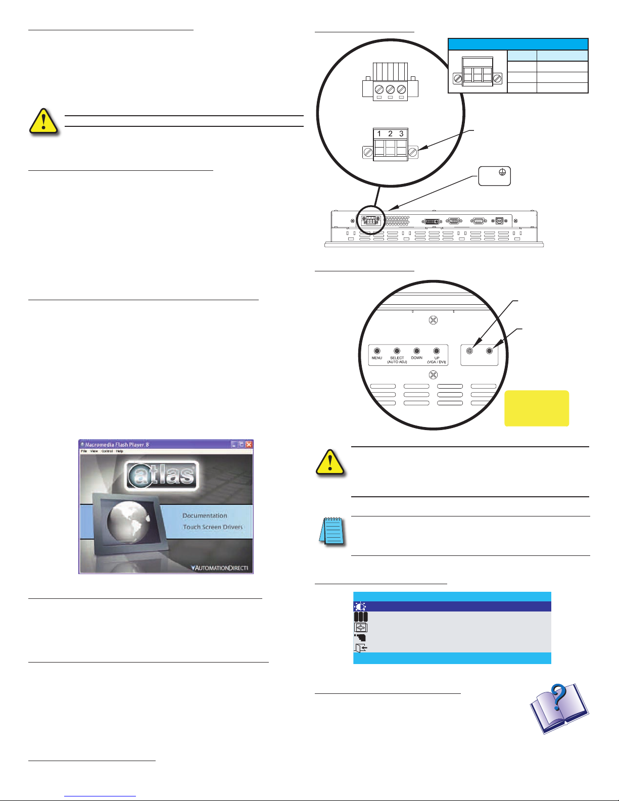
5. Connect Power to the Monitor
• Power source needs to be 100 - 240 VAC, 50/60 Hz, 욷35 Watts.
• See connection diagram below.
• Secure power connector screws to monitor.
• Power should not be applied until all cables are attached and the
monitor is ready to operate.
TOP VIEW
FRONT VIEW
ADC P.N. ATM-AC-CON or
PHOENIX CONTACT P.N. 1777992
L N
Plug Retention Screws
Power
Connection
Label
PE
Power Connections:
100 VAC - 240 VAC INPUT (1.0 Amps Min)
PIN No. Definition
1 AC Line Input
2 AC Neutral Return
3 Protective Earth Ground
WARNING: Dama e can occur if power is not properly connected.