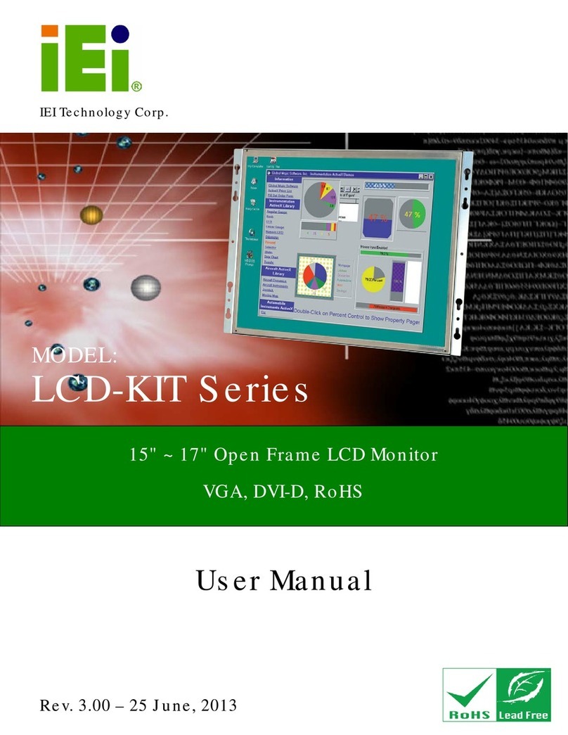
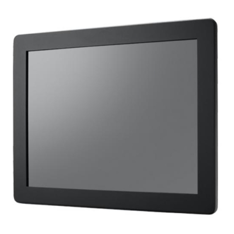
IEI Technology ISDM-084G User manual

ISDM Series Industrial Monitor
Page 1
IEI Technology Corp.
User Manual
ISDM Series Industrial Monitor User Manual
MODEL:
ISDM Series
Stainless Steel Industrial Monitor, RoHS Compliance
IP 65 Protection, Touch Screen, 9-36V DC Input, VGA/DVI-D
Rev. 1.13 – 16 July, 2009

ISDM Series Industrial Monitor
Page 2
Revision
Date Version
Changes
16 July, 2009 1.13 Update “Chapter 6: OSD Controls”
April, 2008 1.12 1. Added ISDM-121GX models information
2. Added the smartOSD appendix
May, 2007 1.11 AV-5300 AD Board CN25 connector pin 3 voltage changed to
+9V~+36V input
April, 2007 1.10 Updated Figure 1-3 and Section 4.3 for AV-5300 AD Board V2.0
October, 2006 1.00 Initial Release

ISDM Series Industrial Monitor
Page 3
Copyright
COPYRIGHT NOTICE
The information in this document is subject to change without prior notice in order to
improve reliability, design and function and does not represent a commitment on the part
of the manufacturer.
In no event will the manufacturer be liable for direct, indirect, special, incidental, or
consequential damages arising out of the use or inability to use the product or
documentation, even if advised of the possibility of such damages.
This document contains proprietary information protected by copyright. All rights are
reserved. No part of this manual may be reproduced by any mechanical, electronic, or
other means in any form without prior written permission of the manufacturer.
TRADEMARKS
All registered trademarks and product names mentioned herein are used for identification
purposes only and may be trademarks and/or registered trademarks of their respective
owners.

ISDM Series Industrial Monitor
Page 4
Manual Conventions
WARNING!
Warnings appear where overlooked details may cause damage to the equipment or result
in personal injury. Warnings should be taken seriously. Warnings are easy to recognize.
The word “warning” is written as “WARNING,” both capitalized and bold and is followed by
text. The text is the warning message. A warning message is shown below:
WARNING:
This is an example of a warning message. Failure to adhere to warning
messages may result in permanent damage to the ISDM Series or
personal injury to the user. Please take warning messages seriously.
CAUTION!
Cautionary messages should also be heeded to help reduce the chance of losing data or
damaging the ISDM Series. Cautions are easy to recognize. The word “caution” is written
as “CAUTION,” both capitalized and bold and is followed. The italicized text is the
cautionary message. A caution message is shown below:

ISDM Series Industrial Monitor
Page 5
CAUTION:
This is an example of a caution message. Failure to adhere to cautions
messages may result in permanent damage to the ISDM Series.
Please take caution messages seriously.
NOTE:
These messages inform the reader of essential but non-critical information. These
messages should be read carefully as any directions or instructions contained therein can
help avoid making mistakes. Notes are easy to recognize. The word “note” is written as
“NOTE,” both capitalized and bold and is followed by text. The text is the cautionary
message. A note message is shown below:
NOTE:
This is an example of a note message. Notes should always be read.
Notes contain critical information about the ISDM Series. Please take
note messages seriously.

ISDM Series Industrial Monitor
Page 6
Packing List
NOTE:
If any of the components listed in the checklist below are missing,
please do not proceed with the installation. Contact the IEI reseller or
vendor you purchased the ISDM Series from or contact an IEI sales
representative directly. To contact an IEI sales representative, please
The items listed below should all be included in the ISDM Series package.
1 x ISDM-190/170/150/121/104/84 series industrial monitor.
1 x AC Power cable
1 x VGA Cable
1 x 45W AC Power Adapter (ISDM-190 / 170 / 150 / 121)
1 x 25W AC Power Adapter (ISDM-104 / 84)
5 x Replacement Round Head Screw
5 x Replacement Flat Head Screw
5 x Replacement Wire Strain Band
1 x User Manual on CDROM
1 x Power Cable for Terminal Block (Optional for M model)
1 x Touch Panel RS-232 Cable / Touch Pen / Driver CDROM (for T-R model)
1 x Touch Panel USB Cable / Touch Pen / Driver CDROM (for USB/T-R
model)
Images of the above items are shown in Chapter 5.

ISDM Series Industrial Monitor
Page 7
Table of Contents
1INTRODUCTION................................................................................................... 18
1.1 ISDM SERIES INDUSTRIAL MONITOR OVERVIEW..................................................... 19
1.1.1 Standard Features............................................................................................ 19
1.1.2 Model Variations.............................................................................................. 19
1.1.3 Base Model Variants ........................................................................................ 20
1.2APPLICATIONS AND FEATURES.................................................................................. 20
1.2.1 ISDM Series Industrial Monitor Applications................................................. 20
1.2.2 ISDM Series Industrial Monitor Features ....................................................... 21
1.3 EXTERNAL OVERVIEW.............................................................................................. 21
1.3.1 Front View........................................................................................................ 22
1.3.2 Bottom Panel View........................................................................................... 22
1.3.3 AD Board ......................................................................................................... 23
1.4 SERIES SPECIFICATIONS............................................................................................ 23
1.5 CERTIFICATIONS....................................................................................................... 25
2MECHANICAL OVERVIEW............................................................................... 26
2.1 INTRODUCTION......................................................................................................... 27
2.2 FRONT PANEL........................................................................................................... 27
2.3 REAR PANEL............................................................................................................. 27
2.4 BOTTOM PANEL........................................................................................................ 28
2.4.1 Available Connectors....................................................................................... 28
2.4.2 ISDM-084 Connectors..................................................................................... 28
2.4.3 ISDM-104 Connectors..................................................................................... 29
2.4.4 ISDM-121 Connectors..................................................................................... 29
2.4.5 ISDM-150 Connectors..................................................................................... 29
2.4.6 ISDM-170 Connectors..................................................................................... 30
2.4.7 ISDM-190 Connectors..................................................................................... 30
2.5 PHYSICAL DIMENSIONS............................................................................................ 31
2.5.1 General Physical Dimensions.......................................................................... 31
2.5.2 ISDM-190 Physical Dimensions...................................................................... 31
2.5.3 ISDM-170 Physical Dimensions...................................................................... 33

ISDM Series Industrial Monitor
Page 8
2.5.4 ISDM-150 Physical Dimensions...................................................................... 34
2.5.5 ISDM-121 Physical Dimensions...................................................................... 35
2.5.6 ISDM-104 Physical Dimensions...................................................................... 36
2.5.7 ISDM-084 Physical Dimensions...................................................................... 37
2.6 OPTIONAL MOUNTING KITS ..................................................................................... 38
2.6.1 ISDM-084 Mounting Kits................................................................................. 38
2.6.2 ISDM-104 Mounting Kits................................................................................. 38
2.6.3 ISDM-121 Mounting Kits................................................................................. 38
2.6.4 ISDM-150 Mounting Kits................................................................................. 39
2.6.5 ISDM-170 Mounting Kits................................................................................. 39
2.6.6 ISDM-190 Mounting Kits................................................................................. 39
2.7 MOUNTING OPTIONS................................................................................................ 40
2.7.1 Panel Mounting................................................................................................ 40
2.7.2 Wall Mounting.................................................................................................. 41
2.7.3 Monitor Arm or Stand Mounting...................................................................... 42
3LCD AND TOUCH PANEL SPECIFICATIONS ................................................ 44
3.1 LCD SPECIFICATIONS............................................................................................... 45
3.1.1 LCD Overview ................................................................................................. 45
3.1.2 ISDM-190 LCD Specifications ........................................................................ 46
3.1.3 ISDM-170 LCD Specifications ........................................................................ 47
3.1.4 ISDM-150 LCD Specifications ........................................................................ 48
3.1.5 ISDM-121 LCD Specifications ........................................................................ 49
3.1.6 ISDM-104 LCD Specifications ........................................................................ 50
3.1.7 ISDM-084 LCD Specifications ........................................................................ 51
3.2 TOUCH PANELS......................................................................................................... 52
3.2.1 Touch Panel Models......................................................................................... 52
3.2.2 Touch Panel Dimensions.................................................................................. 53
3.2.3 Touch Panel Specifications .............................................................................. 54
3.2.4 Touch Panel RS-232 Controller Specifications................................................ 55
3.2.5 Touch Panel USB Controller Specifications.................................................... 56
3.3 POWER ADAPTERS.................................................................................................... 57
4AD BOARDS........................................................................................................... 58
4.1AD BOARD OVERVIEW............................................................................................. 59

ISDM Series Industrial Monitor
Page 9
4.2AV-5350AD BOARD................................................................................................ 59
4.2.1 AV-5350 AD Board Overview .......................................................................... 59
4.2.2 AV-5350 AD Board Connectors ....................................................................... 59
4.2.3 AV-5350 AD Board Layout............................................................................... 60
4.2.4 AV-5350 Peripheral Interface Connectors....................................................... 61
4.2.5 AV-5350 Rear Panel Connectors ..................................................................... 61
4.2.6 AV-5350 On-board Jumper .............................................................................. 62
4.2.7 AV-5350 Internal Peripheral Connectors ........................................................ 62
4.2.8 5V Power Connector........................................................................................ 62
4.2.9 Backlight Inverter Connector .......................................................................... 63
4.2.10 External OSD and LED Indication Connector.............................................. 64
4.2.11 LVDS Output Connector ................................................................................ 66
4.2.12 VGA Connector.............................................................................................. 67
4.2.13 AV-5350 External (Rear Panel) Connectors.................................................. 68
4.2.14 DC 12V Connector......................................................................................... 69
4.2.15 VGA Connector.............................................................................................. 69
4.2.16 AV-5350 On-board Jumper............................................................................ 70
4.2.17 LCD Panel Voltage Select Jumper................................................................. 71
4.3AV-5300AD BOARD OVERVIEW.............................................................................. 72
4.3.1 AV-5300 AD Board Connectors ....................................................................... 73
4.3.2 AV-5300 AD Board Layout............................................................................... 74
4.3.3 AV-5300 Peripheral Interface Connectors....................................................... 75
4.3.4 AV-5300 Rear Panel Connectors ..................................................................... 75
4.3.5 AV-5300 On-board Jumpers............................................................................. 76
4.3.6 AV-5300 Internal Peripheral Connectors ........................................................ 76
4.3.7 Auto-Dimming Connector................................................................................ 76
4.3.8 Debug Port Connector..................................................................................... 77
4.3.9 External OSD and LED Indication Connector................................................ 78
4.3.10 Backlight Inverter Connector ........................................................................ 79
4.3.11 LVDS Output Connector ................................................................................ 80
4.3.12 Power Output Connector............................................................................... 81
4.3.13 Power Input Connector.................................................................................. 82
4.3.14 VGA Connector.............................................................................................. 84
4.3.15 AV-5300 On-board Jumpers........................................................................... 85
4.3.16 LCD Panel Power Input Jumper.................................................................... 86
ISDM Series Industrial Monitor
Page 10
4.3.17 LCD Panel Voltage Select Jumper................................................................. 86
4.3.18 AV-5300 External (Rear Panel) Connectors.................................................. 87
4.3.19 DC 12V Connector......................................................................................... 87
4.3.20 VGA Connector.............................................................................................. 88
4.3.21 DVI-D Connector........................................................................................... 89
5INSTALLATION .................................................................................................... 91
5.1 INSTALLATION PRECAUTIONS................................................................................... 92
5.2 UNPACKING.............................................................................................................. 93
5.2.1 Packaging ........................................................................................................ 93
5.2.2 Unpacking Procedure ...................................................................................... 93
5.2.3 Packing List ..................................................................................................... 94
5.3 PRE-INSTALLATION PREPARATION ............................................................................ 94
5.3.1 Tools................................................................................................................. 94
5.3.2 Voltage Select Jumper Settings ........................................................................ 95
5.4 CONNECTORS ........................................................................................................... 96
5.4.1 Rear Panel Connectors Overview.................................................................... 97
5.4.2 VGA Connector................................................................................................ 97
5.4.3 DVI-D Connector............................................................................................. 98
5.4.4 12V Power Connector...................................................................................... 98
5.4.5 Optional DC Power Connector ....................................................................... 99
5.4.6 Optional RS-232 Touch Panel Connector........................................................ 99
5.4.7 Optional USB Touch Panel Connector .......................................................... 100
5.5 MOUNTING THE ISDM SERIES INDUSTRIAL MONITOR ........................................... 101
5.5.1 Panel Mounting.............................................................................................. 101
5.5.1.1 Standard Panel Mounting........................................................................ 101
5.5.2 Wall Mounting................................................................................................ 104
5.5.3 Monitor Stand Installation............................................................................. 106
5.5.4 Monitor Arm Installation............................................................................... 107
6ON-SCREEN-DISPLAY (OSD) CONTROLS ................................................... 109
6.1 USER MODE OSD STRUCTURE................................................................................110
6.1.1 OSD Buttons....................................................................................................110
6.1.2 OSD Menu Structure.......................................................................................111
6.2 USING THE OSD......................................................................................................112

ISDM Series Industrial Monitor
Page 11
6.2.1 Main Display Features....................................................................................112
6.2.2 Gamma............................................................................................................113
6.2.3 Color...............................................................................................................114
6.2.4 Image Settings.................................................................................................115
6.2.5 OSD Configurations........................................................................................116
6.2.6 Signal ..............................................................................................................117
7SOFTWARE DRIVERS........................................................................................119
7.1 INTRODUCTION....................................................................................................... 120
7.2 DRIVER INSTALLATION........................................................................................... 120
7.3 TOUCH PANEL DRIVER CONFIGURATION ................................................................ 127
ASAFETY PRECAUTIONS................................................................................... 129
A.1 SAFETY PRECAUTIONS .......................................................................................... 130
A.1.1 General Safety Precautions........................................................................... 130
A.1.2 Anti-static Precautions .................................................................................. 131
A.2 MAINTENANCE AND CLEANING PRECAUTIONS...................................................... 131
A.2.1 Maintenance and Cleaning............................................................................ 131
A.2.2 Cleaning Tools............................................................................................... 132
BCERTIFICATIONS.............................................................................................. 133
B.1 ROHS COMPLIANT ................................................................................................ 134
B.2 IP65 COMPLIANT FRONT PANEL ........................................................................... 134
CSMARTOSD.......................................................................................................... 135
C.1 IEI SMARTOSD QUICK INSTALLATION GUIDE ....................................................... 136
C.2 PRE-INSTALLATION NOTICE................................................................................... 136
C.3 SMARTOSD INSTALL ............................................................................................. 136
C.4 SOFTWARE ILLUSTRATION ..................................................................................... 140
C.4.1 Manage Page................................................................................................. 142
C.4.2 EDID Page.................................................................................................... 143
C.4.3 Image Page.................................................................................................... 144
C.4.4 Display Page (for analog signal).................................................................. 145
C.4.5 Color Page .................................................................................................... 146
C.4.6 PIP Page........................................................................................................ 147
C.4.7 System Page................................................................................................... 148

ISDM Series Industrial Monitor
Page 12
C.4.8 About Page.................................................................................................... 149
C.5 SMARTOSD FAQ................................................................................................... 150
C.5.1 Windows 2000 Installation Failure............................................................... 150
C.5.2 Vista Installation Failure............................................................................... 151
C.5.3 Model Failure................................................................................................ 152
C.5.4 DCC Port Failure.......................................................................................... 152

ISDM Series Industrial Monitor
Page 13
List of Figures
Figure 1-1: ISDM Series Front View...........................................................................22
Figure 1-2: Typical Bottom Panel View.....................................................................22
Figure 1-3: AV-5300 AD Board...................................................................................23
Figure 2-1: Front Panel...............................................................................................27
Figure 2-2: Rear Panel ................................................................................................28
Figure 2-3: ISDM-190 Physical Dimensions (millimeters).......................................32
Figure 2-4: ISDM-170 Physical Dimensions (millimeters).......................................33
Figure 2-5: ISDM-150 Physical Dimensions (millimeters).......................................34
Figure 2-6: ISDM-121 Physical Dimensions (millimeters).......................................35
Figure 2-7: ISDM-104 Physical Dimensions (millimeters).......................................36
Figure 2-8: ISDM-084 Physical Dimensions (millimeters).......................................37
Figure 2-9: Typical Panel Mounting...........................................................................40
Figure 2-10: Typical Wall Mounting...........................................................................41
Figure 2-11: Typical Monitor Arm or Stand Mounting.............................................42
Figure 4-1: AV-5350 AD Board Overview..................................................................59
Figure 4-2: Connector and Jumper Locations .........................................................60
Figure 4-3: 5V Power Connector Location ...............................................................63
Figure 4-4: Backlight Inverter Connector Location.................................................64
Figure 4-5: External OSD and LED Indication Connector Location.......................65
Figure 4-6: LVDS Output Connector Location .........................................................67
Figure 4-7: VGA Connector Location........................................................................68
Figure 4-8: AV-5350 External (Rear Panel) Connectors..........................................69
Figure 4-9: VGA Connector Pinout Locations..........................................................70
Figure 4-10: Jumpers..................................................................................................70
Figure 4-11: Jumper Location....................................................................................71
Figure 4-12: AV-5300 AD Board Overview................................................................72
Figure 4-13: Connector and Jumper Locations .......................................................74

ISDM Series Industrial Monitor
Page 14
Figure 4-14: Auto-dimming Connector Location .....................................................77
Figure 4-15: Debug Port Connector Location ..........................................................78
Figure 4-16: External OSD and LED Indication Connector Location.....................79
Figure 4-17: Backlight Inverter Connector Location...............................................80
Figure 4-18: LVDS Output Connector Location .......................................................81
Figure 4-19: Power Output Connector Locations....................................................82
Figure 4-20: Power Input Connector Locations.......................................................83
Figure 4-21: VGA Connector Location......................................................................84
Figure 4-22: Jumpers..................................................................................................85
Figure 4-23: Jumper Locations..................................................................................85
Figure 4-24: AV-5300 External (Rear Panel) Connectors........................................87
Figure 4-25: VGA Connector Pinout Locations........................................................88
Figure 4-26: DVI-D Connector Pinout Locations......................................................90
Figure 5-1: Monitor Rear Panel Connections...........................................................97
Figure 5-2: VGA Connector........................................................................................98
Figure 5-3: DVI-D Connector......................................................................................98
Figure 5-4: 12V Power Connector..............................................................................99
Figure 5-5: DC Power Connector...............................................................................99
Figure 5-6: Optional RS-232 Touch Panel Connector .......................................... 100
Figure 5-7: Optional USB Touch Panel Connector............................................... 100
Figure 5-8: Panel Opening....................................................................................... 102
Figure 5-9: Insert the Monitor ................................................................................. 102
Figure 5-10: Panel Mounting Clamp Position........................................................ 103
Figure 5-11: Wall-mounting Bracket....................................................................... 104
Figure 5-12: Monitor Support Screws.................................................................... 105
Figure 5-13: Wall Mounting the Monitor................................................................. 106
Figure 5-14: VESA Mounting Holes........................................................................ 106
Figure 5-15: Monitor Stand Mounting .................................................................... 107
Figure 5-16: Monitor Arm Mounting....................................................................... 108
Figure 6-1: OSD Control Buttons for ISDM Series................................................ 110
Figure 6-2: Main Display Features.......................................................................... 112
Figure 6-3: Color Options........................................................................................ 113

ISDM Series Industrial Monitor
Page 15
Figure 6-4: Color Options........................................................................................ 114
Figure 6-5: Image Settings Menu............................................................................ 115
Figure 6-6: OSD Configurations Menu................................................................... 116
Figure 6-7: Signal Menu........................................................................................... 117
Figure 7-1: Driver CD Pop Up Screen..................................................................... 121
Figure 7-2: Install Shield Wizard Preparation........................................................ 122
Figure 7-3: Welcome Screen................................................................................... 122
Figure 7-4: Install PS/2 Interface Driver................................................................. 123
Figure 7-5: Install PS/2 Interface Driver................................................................. 124
Figure 7-6: Touch Monitor/USB Touch Controller Confirmation ........................ 124
Figure 7-7: Controller Installation Directory.......................................................... 125
Figure 7-8: Program Icon Directory........................................................................ 126
Figure 7-9: Installing................................................................................................ 126
Figure 7-10: Installation Complete ......................................................................... 127
Figure 8-2: smartOSD Installer ............................................................................... 137
Figure 8-3: smartOSD Welcome Screen ................................................................ 137
Figure 8-4: smartOSD Folder Select Screen ......................................................... 138
Figure 8-5: smartOSD Confirm Installation ........................................................... 138
Figure 8-6: smartOSD Installation Progress ......................................................... 139
Figure 8-7: smartOSD Installation Complete......................................................... 139
Figure 8-8: Manage Page......................................................................................... 142
Figure C-9: DLL Missing.......................................................................................... 150
Figure C-10: Windows Vista Error.......................................................................... 151
Figure C-11: Install as Administrator..................................................................... 151
Figure C-12: Firmware Incompatibility................................................................... 152
Figure C-13: DCC Port Failure ................................................................................ 152

ISDM Series Industrial Monitor
Page 16
List of Tables
Table 1-1: ISDM Series Base Model Variants...........................................................20
Table 1-2: ISDM Series Specifications......................................................................25
Table 2-1: General Physical Dimensions..................................................................31
Table 2-2: ISDM-084 Mounting Kits...........................................................................38
Table 2-3: ISDM-104 Mounting Kits...........................................................................38
Table 2-4: ISDM-121 Mounting Kits...........................................................................39
Table 2-5: ISDM-150 Mounting Kits...........................................................................39
Table 2-6: ISDM-170 Mounting Kits...........................................................................39
Table 2-7: ISDM-190 Mounting Kits...........................................................................40
Table 2-8: Panel Mounting Clamps............................................................................41
Table 3-1: ISDM-190 LCD Specifications ..................................................................46
Table 3-2: ISDM-170 LCD Specifications ..................................................................47
Table 3-3: ISDM-150 LCD Specifications ..................................................................48
Table 3-4: ISDM-121 LCD Specifications ..................................................................49
Table 3-5: ISDM-104 LCD Specifications ..................................................................50
Table 3-6: ISDM-084 LCD Specifications ..................................................................51
Table 3-7: Touch Panel Models..................................................................................52
Table 3-8: Touch Panel Dimensions (mm)................................................................53
Table 3-9: Touch Panel Specifications......................................................................54
Table 3-10: Touch Panel RS-232 Controller Specifications....................................55
Table 3-11: Touch Panel USB Controller Specifications.........................................56
Table 3-12: Power Adapter Specifications ...............................................................57
Table 4-1: AV-5350 Peripheral Interface Connectors ..............................................61
Table 4-2: AV-5350 Rear Panel Connectors .............................................................61
Table 4-3: AV-5350 On-board Jumper.......................................................................62
Table 4-4: 5V Power Connector Pinouts...................................................................62
Table 4-5: Backlight Inverter Connector Pinouts.....................................................63
Table 4-6: External OSD and LED Indication Connector Pinouts ..........................65

ISDM Series Industrial Monitor
Page 17
Table 4-7: LVDS Output Connector Pinouts.............................................................66
Table 4-8: VGA Connector Pinouts ...........................................................................68
Table 4-9: DC 12V Connector Pinouts.......................................................................69
Table 4-10: VGA Connector Pinouts .........................................................................70
Table 4-11: LCD Panel Voltage Select Jumper Settings .........................................71
Table 4-12: AV-5300 Peripheral Interface Connectors ............................................75
Table 4-13: AV-5300 Rear Panel Connectors ...........................................................76
Table 4-14: AV-5300 On-board Jumpers...................................................................76
Table 4-15: Auto-dimming Connector Pinouts.........................................................77
Table 4-16: Debug Port Connector Pinouts..............................................................78
Table 4-17: External OSD and LED Indication Connector Pinouts........................79
Table 4-18: Backlight Inverter Connector Pinouts...................................................80
Table 4-19: LVDS Output Connector Pinouts...........................................................81
Table 4-20: Power Output Connector Pinouts (CN12).............................................82
Table 4-21: Power Output Connector Pinouts (CN13).............................................82
Table 4-22: Power Input Connector Pinouts (CN24)................................................83
Table 4-23: Power Input Connector Pinouts (CN25)................................................83
Table 4-24: VGA Connector Pinouts .........................................................................84
Table 4-25: LCD Panel Power Input Jumper Settings .............................................86
Table 4-26: LCD Panel Voltage Select Jumper Settings .........................................86
Table 4-27: DC 12V Connector Pinouts.....................................................................87
Table 4-28: VGA Connector Pinouts .........................................................................88
Table 4-29: DVI-D Connector Pinouts .......................................................................89
Table 5-1: Rear Panel Connectors.............................................................................96
Table 5-2: VGA Connector Pinouts ...........................................................................97
Table 5-3: DVI-D Connector Pinouts .........................................................................98
Table 5-4: Optional RS-232 Touch Panel Connector Pinouts.............................. 100
Table 5-5: Optional USB Touch Panel Connector Pinouts .................................. 100
Table 6-1: OSD Menus ............................................................................................. 111
Table C-1: SmartOSD Menu Structure ................................................................... 141

ISDM Series Industrial Monitor
Page 18
1 Introduction
Chapter
1

ISDM Series Industrial Monitor
Page 19
1.1 ISDM Series Industrial Monitor Overview
The ISDM series industrial monitor is the latest member of IEI’s line of sophisticated LCD
designs, and it has been improved to be RoHS compliant. With the stainless steel frame,
the ISDM series is ideal for strict hygiene conditions, such as hospital, kitchens, abattoirs
and other food processing plants. The ISDM series is also designed to fit industrial
automation, or any other applications that require minimum installation space and
flexible configuration. The flat front panel provides IP 65 protection, which effectively
wards off dust and water. Flexible analog or digital interfaces are provided for ease of
connection with a management computer. All the ISDM series models come with a
resistive type touch panels. If remote/non-attentive control is preferred, RS-232 or USB
interfaces can be used with customized adapter cables.
1.1.1 Standard Features
All the base models listed in Section 1.2.1 have the following standard features
LCD monitor
Stainless steel front frame
Heavy-duty steel chassis
OSD function
IP 65 level protection
RoHS compliance
1.1.2 Model Variations
The ISDM LCD series have the following seven base models.
ISDM-084G: 8.4” LCD screen
ISDM-104G: 10.4” LCD screen
ISDM-121G: 12.1” LCD screen
ISDM-150G: 15” LCD screen
ISDM-170G: 17” LCD screen
ISDM-190G: 19” LCD screen

ISDM Series Industrial Monitor
Page 20
1.1.3 Base Model Variants
The ISDM series industrial monitor base models may or may not have a variety of variants.
The standard model name is ISDM-(XXX)G, where (XXX) refers to three digit size of the
monitor. Special features with the associated model prefix are listed in Table 1-1.
Model Number
High
Luminance
9~36V
Power
Input
Touch
Screen
USB
Touch
Screen
ISDM-(XXX)G/T-R - - Yes -
ISDM-(XXX)GM/T-R - Yes Yes -
ISDM-(XXX)GH/T-R Yes - Yes -
ISDM-(XXX)GHM/T-R Yes Yes Yes -
ISDM-(XXX)G-USB/T-R - - - Yes
ISDM-(XXX)GM-USB/T-R - Yes - Yes
ISDM-(XXX)GX/T-R - - Yes -
ISDM-(XXX)GXM/T-R - Yes Yes -
ISDM-(XXX)GX-USB/T-R - - - Yes
ISDM-(XXX)GXM-USB/T-R - Yes - Yes
Table 1-1: ISDM Series Base Model Variants
1.2 Applications and Features
1.2.1 ISDM Series Industrial Monitor Applications
The ISDM series industrial monitor is designed for strict hygiene conditions or rigorous
industrial environments. Its durability and strength also makes it an ideal choice for public
access computers. Some possible applications include:
Automation & Control
oFood processing plant environment monitoring
oFactory automation HMI terminal
oShop-floor/MES control
Digital Surveillance
oDigital surveillance
This manual suits for next models
5
Table of contents
Other IEI Technology Industrial Monitor manuals