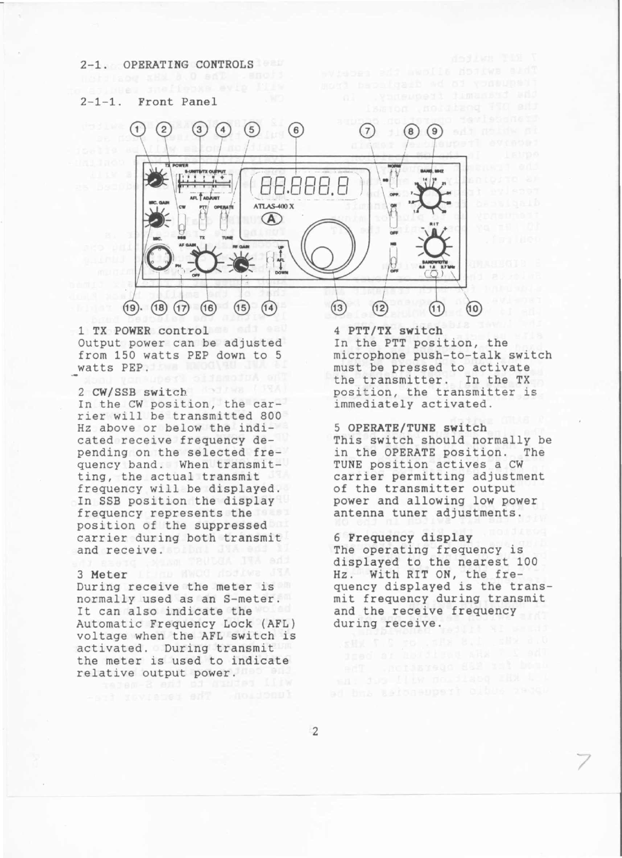
7 RIT switch
This switch allows the receive
frequency to be displaced from
the transmit frequency. In
the OFF position, normal
transceiver operation occurs
in which the transmit and
receive frequencies remain
equal. In the ON position,
the transmit frequency remains
as originally set and the
receive frequency can be
displaced from the transmit
frequency up to plus or minus
10
kHz by positioning the RIT
control.
8 SIDEBAND (SB) switch
Selects the upper or lower
sideband for both transmit and
receive. On frequencies below
the 14 MHz band NORMal selects
the lower sideband and OPPo-
site selects the upper side-
band. On frequencies in the
14 MHz band and above NORMal
-selects the upper sideband and
OPPosite selects the lower
sideband.
9 BAND switch
The nine amateur bands between
1.8 MHz and 30 MHz can be
selected by this switch. The
10 meter band has two posi-
tions.
10 RIT control
With the RIT switch in the ON
position, the RIT control can
displace the receive frequency
by plus or minus 10 kHz rela-
tive to that of the transmit
frequency.
11 BANDWIDTH switch
This switch selects one of
three IF filter bandwidths,
0.6 kHz, 1.8 kHz, or 2.7 kHz.
The 2.7 kHz position is best
used for SSB operation. The
1.8 kHz position will cut the
upper audio frequencies and be
useful in crowed band condi-
tions. The 0.6 kHz position
will give excellent results on
CWo
12 NOISE BLANKER (HB).switch
Pulse type noises, such as
ignition noise will be effect-
ively silenced. More continu-
ous type noise signals will
not be silenced or reduced as
much.
13 TUNING dial (VFO)
Tuning the transceiver is
accomplished by rotating one
of the two concentric tuning
knobs. The large aluminum
knob tunes at a rate six times
that of the smaller black knob
and can be used to move rapid-
ly within the selected band.
Use the smaller black knob for
final frequency setting.
14 AFL UP/DOWN switch
The Automatic Frequency Lock
(AFL) switch provides a means
to reset the AFL offset volt-
age. When the AFL UP/DOWN
switch is put into either the
UP or DOWN position, the AFL
voltage is shown on the S-
UNITS/OUTPUT meter. If the
AFL voltage reads either full
scale or zero scale, the AFL
UP/DOWN switch must be used to
reset the AFL voltage to the
indicated AFL ADJUST point
located below the meter scale.
If the AFL indication is above
the AFL ADJUST mark, press the
AFL switch DOWN until the
meter is at the AFL ADJUST
mark. If the AFL voltage is
below the mark press the
switch UP. After setting the
AFL voltage the AFL switch
must be returned to the center
position. With the switch in
the center position the meter
will return to the S-meter
function. The receiver fre-
3