Atlona AT-HDAIR User manual

AtlonA
Wireless VGA and HDMI with Audio
AT-HDAIR
User Manual
Connect any PC via USB Wirelessly
to your Computer Monitor and HDTV display.
NOTE:
The AT-HDAIR is designed to extend your desktop to an additional monitor. Using this product in mirrored mode
causes additional strain on your computer’s processor, and may affect overall video quality.
PLEASE USE EXTENDED MODE TO GET BETTER RESULTS.

TABLE OF CONTENTS
1. What’s in the Package .................................................. 1
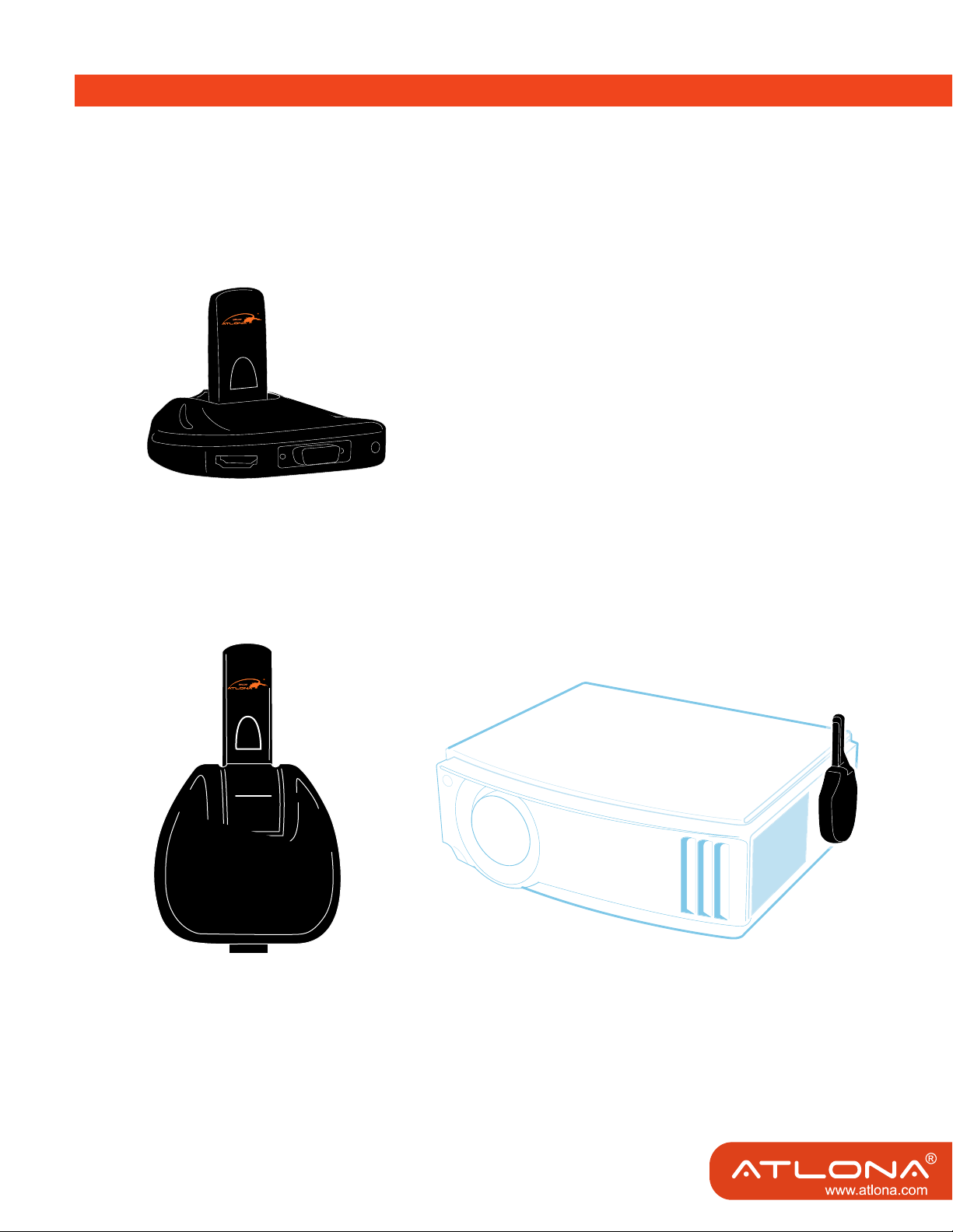
2. Positioning the Adapters .................................................. 2
2.1 Positioning the A/V Adapter .................................................. 2
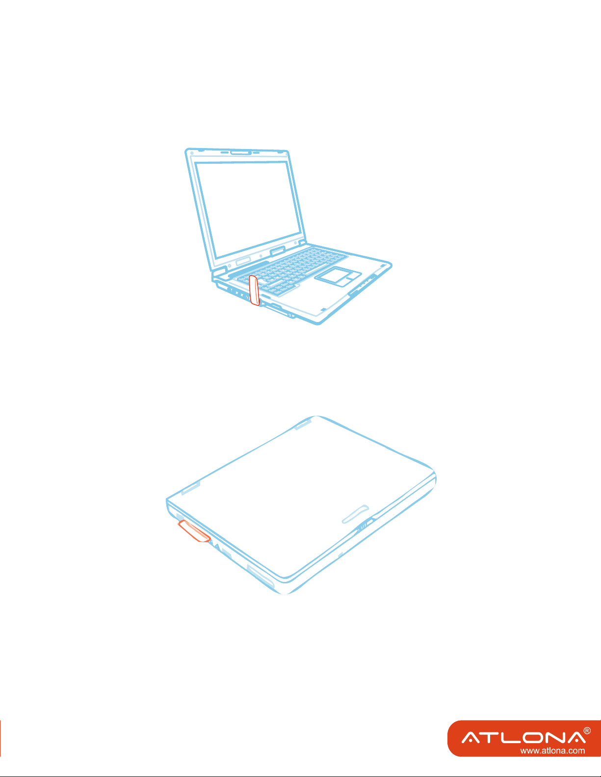
2.2 Positioning the PC Adapter .................................................. 3
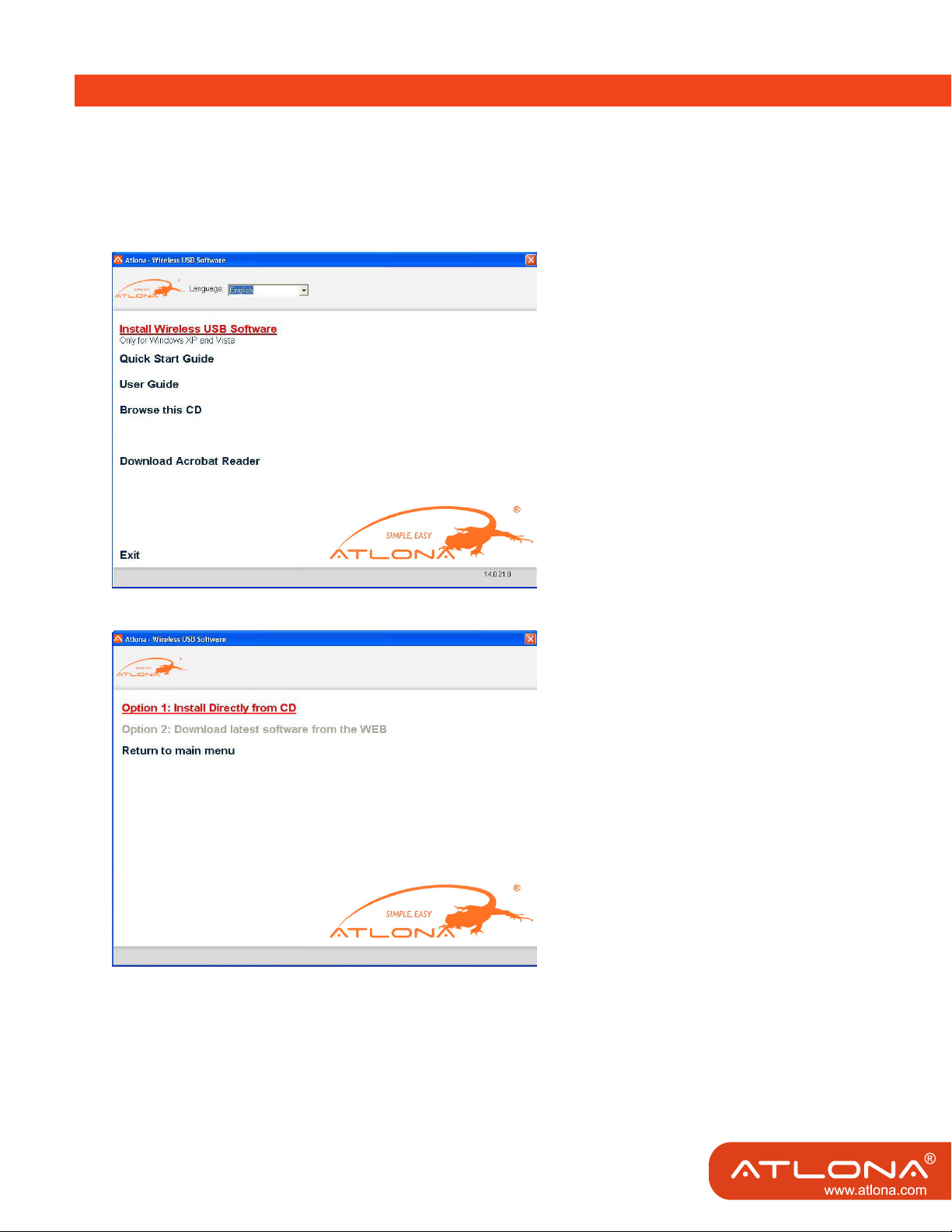
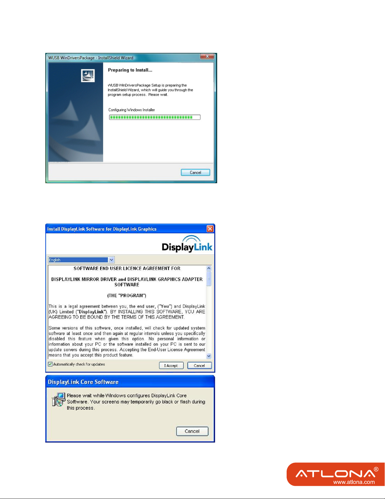
3. Software Installation and First Connection .................................................. 4
3.1 Connect the PC Adapter to the PC .................................................. 7
3.2 Connect the Display Adapter .................................................. 8
3.2.1 Connecting Audio .................................................. 8
4. Wireless USB Manager User Interface .................................................. 9
4.1 Wireless USB Manager System Tray Icon .................................................. 9
4.2 Accessing the Wireless USB Manager .................................................. 9
4.3 Blocking or Disassociating a Device .................................................. 12
4.4 Changing Device Names in the Wireless USB Manager ................................. 13
4.5 Advanced Settings .................................................. 13
5. Using and Conguring the Display Adapter .................................................. 15
5.1 Using the A/V Adapter .................................................. 15
5.1.1 Using Mirror Mode .................................................. 15
5.1.2 Using Extend Mode .................................................. 16
5.1.3 Laptop Operation with the Lid Closed ..................................... 17
5.1.4 External Display Only .................................................. 17
5.2 Conguring the Display via the Display Icon Context Menu ........................ 17
5.2.1 Setting Mirror Mode .................................................. 19
5.2.2 Setting Extend Mode .................................................. 20
5.3 Conguring the Display via Windows Display Properties ................................. 21
5.3.1 Selecting the Correct Display Monitor .............................................. 21
5.3.2 Setting the Display to Extend or Mirror Mode .................................. 22
5.3.3 Adjusting Screen Resolution .................................................. 22
5.3.4 Adjusting Color Level .................................................. 22
5.3.5 Setting the A/V Adapter as the Primary Display ........................ 22
5.4 Optimizing Wireless Video Display .................................................. 23
5.4.1 Optimizing Internet Video Viewing .................................................. 23
5.4.2 Setting Aero Desktop Theme in Vista .............................................. 24
5.4.3 Recommended Media Player Applications ...................................... 25
5.4.4 Recommended Minimum System Requirements ............................ 25
5.5 Setting Audio Output Device .................................................. 25
6. LED Indications .................................................. 27
7. Appendix A: Troubleshooting Help .................................................. 27
8. Appendix B: Pairing Procedure .................................................. 31
9. Safety Information .................................................. 33
10. Warranty .................................................. 34
11. Product registration .................................................. 35

1. What’s in the Package
1
A/V Adapter
Software CD
PC Adapter
Power Supply Unit
Device Adapter
A/V Base
HDMI VGA 3.5mm Audio
Power

2
2. Positioning the Adapters
2.1 Positioning the A/V Adapter
The Wireless USB A/V Adapter is designed for two possible mounting options:
• Simple table placement – the Audio/Video Base (A/V Base) is placed on a at horizontal sur-
face, and the Device Adapter is connected at 90 degrees to the base so that it is vertical.
• Vertical mounting –the A/V Base is fastened to a wall, a projector, or behind a display
screen, and the Device Adapter is connected so that it is at with the mounting surface, with
the Device Adapter pointing upwards.
Note: For best performance, it is recommended to always position the Device Adapter vertically so that
it is pointing upwards.

2
2.2 Positioning the PC Adapter
To achieve best performance it is recommended to position the PC Adapter in the upright posi-
tion.
Figure 1: PC in working mode - PC Adapter in upright position
When the laptop is not in use, the PC Adapter can be rotated 90 degrees for storage, as seen
in the following illustration:
Figure 2: Laptop inactive - PC adapter in horizontal position for storage.
3

Note: If your PC contains a previous Wireless USB Suite driver installation, please perform a proper
uninstall procedure using the Windows Control Panel.
1. Ensure that the PC Adapter is unplugged from the PC.
2. Insert the installation CD in the PC CD-ROM drive.
3. The installation CD Autoplay menu is displayed.
4. Select Install Wireless USB Software.
The installer offers two options:
• Option 1: Install Directly from CD - initiates the installation process from the CD.
• Option 2: Download latest software from the WEB - provides a link to a web address where
you can download software updates. If you choose this option, follow the instructions provided
on the software download page.
4
3. Software Installation and First Connection

5. If you select Option 1: Install Directly from CD, the install wizard begins installing the Wire-
less USB software. The installation process may include more than one stage to accom-
modate different drivers that are installed. Following the Wireless USB drivers, the Display
drivers and application are installed.
6.Choose your geographic region to comply with your local radio regulations. This setting can
be changed if needed once the software is installed.
7.Follow the onscreen instructions, and proceed by clicking Next> when prompted, or by ap-
proving authorization requests to continue the installation.
54

8. When the Wireless USB Driver installation has completed, the Display driver installation be-
gins.
Click I Accept to approve the end-user license agreement and continue installation.
6

6 7
9. When the installation procedure has successfully nished, you are automatically returned to
the opening screen of the Autoplay menu. You may be requested to reboot.
3.1 Connect the PC Adapter to the PC
• Connect the Wireless USB PC Adapter to a high speed PC USB port. The system will auto-
matically detect and install the drivers for the connected PC Adapter
Windows VISTA Windows XP
• System Tray icon turns red to indicate that the PC Adapter (Host) is ready to connect to
any paired device in range
Windows VISTA Windows XP

8
3.2. Connect the A/V Adapter
1. Attach the A/V Adapter to the remote display device (TV/Projector/Monitor), and ensure the
PC (with PC Adapter attached) is within 3 meter distance from the A/V Adapter for the initial
connection. Ensure the two adapters have clear line-of-sight. Connect the provided power sup-
ply to the A/V Base power receptacle.
Note: The PC Adapter and Device Adapter in this set are already paired and do not require performing a pair-
ing procedure. If you should need to perform pairing manually for any reason (e.g. connecting to a new host
PC Adapter, or adding a Device Adapter that was not purchased in a set), please refer to Appendix B: Pairing
Procedure
2. Wait for the System Tray icon to turn green , indicating that a wireless connection with
the A/V Adapter has been established. The Display icon is also displayed as soon as a
connection is established and the Display drivers are active.
Note: If you do not see the icon changing to green, or do not see the Display icon, please see Appendix A:
Troubleshooting Help for suggestions.
3.2.1 Connecting Audio
The following options can be used to connect an Audio Output Device to the A/V Adapter:
Using the HDMI connector. Connect the HDMI cable to the A/V Base. Both video and audio
are delivered on the same HDMI cable. Connect the other end of the cable to the appropriate
HDMI port on the TV/Projector/Monitor.
Using the dedicated 3.5mm port. Connect an audio cable with a 3.5mm (mini-stereo) plug to
the audio jack on the A/V Base. Connect the other end of the cable to the appropriate audio
input jack on the audio device.
Note: The audio output is activated automatically. If you need to set the audio output device manually,
see 5.5 Setting Audio Output Device.

9
The Wireless USB Manager allows you to monitor and control the available Wireless USB de-
vices and connections that are within range of the PC.
4.1 Wireless USB Manager System Tray Icon
The Wireless USB Manager icon is automatically displayed in the Windows System Tray when-
ever Windows starts. The color and shape of the icon indicates the current activity state, as
described in the following table:
Icon Color Status
Connected (green icon)
A wireless connection is established with a Wireless USB Device Adapter.
Host Hardware Enabled (red icon)
Wireless USB PC Adapter is connected to the PC (PC Adapter is enabled), but no wire-
less connection is detected.
Host Hardware Disconnected (gray icon)
Wireless USB PC Adapter is not connected.
Host Hardware Disabled (gray icon with X)
Wireless USB PC Adapter is disabled.
Note: Under the Japan regional setting, this icon is displayed whenever the AC power
source is disconnected from the PC.
Wireless USB Channel is Busy (green icon with exclamation)
Low channel quality detected, but at least one Wireless USB device is still connected. To
improve connection quality, see Appendix A: Troubleshooting Help for suggestions.
Wireless USB Channel is not available (red icon with exclamation)
No available channel detected. To improve connection quality, see Appendix A: Trouble-
shooting Help for suggestions.
4.2 Accessing the Wireless USB Manager
To access the Wireless USB Manager:
• Right click the Wireless USB Manager System Tray icon and select Wireless USB
Connections to display the Wireless USB Manager screen.
Figure 3: System Tray Icon - Context menu
4. Wireless USB Manager User Interface
8

10
Table 1: Context menu options
Menu Option Description
Wireless USB
Manager
Displays the main user interface, which displays a list of Wireless USB
devices that are available, and their connection status (Connected, Not
Connected, Blocked)
Help Opens the help/troubleshooting le (HTML format) in a browser
About Displays the About screen, containing version information for the drivers
and software.
Exit Closes the Wireless USB Manager application
Figure 4: Wireless USB Manager – remote device connected

10 11
Table 2: Wireless USB Manager options
Menu Option Description
Host ID Displays the currently connected PC Adapter ID number
Connection Quality The following are the different states of the connection status icon which
indicates the connection quality:
Blocked –
Not connected –
Connected –
Medium –
Good –
Very Good –
Excellent –
Advanced Settings Displays the Advanced Settings screen, allows conguration of the PC
Adapter RF settings.
Close Closes the Wireless USB Manager screen, does NOT close the Wire-
less USB Manager application.
About Displays the About screen containing basic information regarding the
software version and vendor details
(Help) Opens the help/troubleshooting le (HTML format) in a browser

12
4.3 Blocking or Disassociating a Device
The Wireless USB Manager screen allows you to remove devices or to temporarily disable
them from connecting to the Host.
To Block a device temporarily, and prevent it from connecting to the Host:
• Right click the device name in the Connection list and select Block Device.
To remove a device from the list of available devices completely:
• Right click the device name in the Connection list and select Disassociate Device.
Note: The Dissociate Device option is only available for device adapters purchased separately
and not in a set with the PC Adapter.
Figure 5: Wireless USB Manager Context Menu
To remove a device from the list of available devices completely:
• Right click the device name in the Connection list and select Disassociate Device
Figure 6: Wireless USB Manager– remote device blocked
Note: The Disassociate Device option is only available for Device Adapters that are pur-
chased separately and not in a set.
For information about pairing an Adapter set, see Appendix B: Pairing Procedure.

12 13
Table 3: Context menu options
Menu Option Description
Block/UnBlock Device Allows you to temporarily disable a device from connecting with the
Host.
Disassociate Device Removes the device from the list. To return the device to the list,
Pairing must be performed again.
Properties Displays the properties screen for this device.
4.4. Changing Device Names in the Wireless USB Manager
The Wireless USB Manager screen allows you to modify the name of the device that appears
in the connections list.
To modify the device name:
1. Double-click the device name
2. Enter the text that you want.
3. Click anywhere outside of the device name area to nalize.
Figure 7: Editing Device Name in Wireless USB Manager
4.5. Advanced Settings
The Advanced Settings screen of the Wireless USB Manager allows viewing advanced set-
tings, and allows conguration of the Channel and Region selection in the Host.
To access the Advanced Settings screen:
• In the Wireless USB Manager screen, click Advanced Settings

14
Figure 8: Advanced Settings Screen
Option Description
Region: Allows selecting the regulatory region: USA, Europe, Japan, Ko-
rea, China
Current Channel (read
only)
Displays the current PHY Channel
Channel Quality (read
only)
Displays Channel quality: Excellent, Very Good, Good, Low, Not
Connected
Select Channel Allows selecting PHY Channels: 13*, 14, 15#
Select Rate (Mbps) This option is not active.
OK Applies conguration changes that were made
Close Closes the Advanced Settings screen
Notes: * This is the default value for USA region.
# This is the only available option for Europe, Japan, Korea and China regions.

14 15
5. Using and Configuring the A/V Adapter
The following are suggested work modes for connecting a display screen to the A/V Adapter:
• Mirror Mode
• Extend Mode
• Laptop with Lid Closed
• External Display Only
Note: The display properties for the A/V Adapter can be congured in two ways: as de-
scribed in Sec. 5.2 Conguring the Display via the Display Icon Context Menu, or as de-
scribed in Sec. 5.3 Conguring the Display via Windows Display Properties.
When changing settings, or during rst connection between the PC Adapter and A/V Adapter,
the PC display may icker or turn on and off as the screen resolution is automatically ad-
justed.
5.1 Using the A/V Adapter
Upon rst time operation, the A/V Adapter is in Extend mode, this section (Sec. 5.1) describes
the different modes that can be set. In Sec. 5.2 and 5.3 you will nd the procedures for congur-
ing these modes.
5.1.1 Using Mirror Mode
Mirror mode is used to display the
identical content on the additional
screen as is shown on the main PC/
Laptop screen. Mirror mode is gen-
erally used to display the PC con-
tents on a larger or higher denition
display. See Figure 9: Mirror Mode
- displaying PC desktop on a larger
display screen.
Note: Mirror mode is not recommended
for playing HD video. Figure 9: Mirror Mode - displaying PC desktop on a larger
display screen

16
5.1.2 Using Extend Mode
Use the Extend mode to display different content on each display screen. In Extend mode, the
display attached to the A/V Adapter becomes an extended part of the Windows desktop. The
extra desktop area is a great productivity aid, allowing you to view or work with more applica-
tions or documents at the same time. You can also use this mode to extend your desktop to ll
multiple screens that are positioned next to each other for a larger continuous work space.
5.1.3 Laptop Operation with the Lid Closed
You can work conveniently with a laptop by setting its default action upon closing the lid to “Do
nothing” (to prevent the laptop from entering “sleep” or “hibernation” mode, Control Panel >
Power Options, “When I close the lid:” - “Do nothing”), and then set the A/V Adapter screen
as the primary display while disabling the main screen (see Sec. 5.3.5 Setting the A/V Adapter
as the Primary Display).
The laptop lid can then be closed, and the laptop can be used with the A/V Adapter screen and
an external keyboard and mouse attached to the laptop. This conguration can be used togeth-
er with either Mirror mode or Extend mode.
Figure 10: Illustration of extend mode
PC screen External
(extended) screen
Note: Extend mode is recommended for playing HD video.
Figure 11: Extend Mode - using second display for an additional application or a movie

16 17
5.1.4. External Display Only
When you want to use the external display only, (see Sec. 5.3.5 Setting the A/V Adapter as the
Primary Display), you can close your main monitor and view movies on the external display at-
tached to the A/V Adapter.
5.2. Conguring the Display via the Display Icon Context Menu
When a link is established with the Wireless USB A/V Adapter, the Display drivers are activated
and the Display icon appears in the Windows system tray.
The right-click context menu of the Display icon contains conguration options that correspond
to the display mode.
Note: When changing settings, the PC display may icker or turn on and off as the screen resolution is automati-
cally adjusted.

18
Conguration Option Options available Remarks
Screen Resolution Extend mode only
Color Quality Extend mode only
Screen Rotation Mirror and Extend modes
Extend To Extend mode only
Extend Sets the Extend mode
Mirror Sets the Mirror mode
Off Disables the remote display Select Mirror or Extend
mode to enable the display
Advanced Opens the Windows Display Settings
screen
Other manuals for AT-HDAIR
2
Table of contents
Other Atlona Adapter manuals