Viking PSA-TB-IP User manual
Specifications
Information: 715-386-8861
www.VikingElectronics.com
• Quick and easy installation
• SIP compliant, see page two for more information
• PoE powered (class 3, <13 Watts)
• Paging prioritization
• Plays audio from standard multicast sources
• SIP endpoint or multicast group member
• Red call status LED indicator
• Automatic Noise Canceling (ANC) feature for operation in noisy
environments
• Proprietary VOX switching eliminates the need for “Push to Talk” mode
• Selectable auto-answer feature for monitoring
• Compatible with Polycom multicast paging
• Built-in high-efficiency 6 Watt class D amplifier
• Can drive up to six 8 Ohm analog speakers for greater coverage
• SIP/Multicast: SIP page, SIP page and zoned multicast receive
• Support for access code to prevent unwanted SIP calls
• Hangs up on: busy signal, time-out, or touch tone command
• Network remote speaker volume control
• Mounting: Magnetically secure to speaker magnet or attach to the
25/70V transformer mounting holes on speaker frame
• Chassis protects circuitry against plenum dust
• Automatic Gain Control (AGC) to automatically increase ring volume to
compensate for ambient noise
• Diagnostics for testing microphone and speaker
• Programmable pre-page alert tone
Power: PoE class 3 (<13 Watts)
Dimensions: 3.63” x 2.65” x 0.90” (92.2 mm x 67.3 mm x 22.9 mm)
Shipping Weight: 0.60 lbs (0.27 kg)
Operating Temperature: -40° F to 140° F (-40° C to 60° C)
Humidity: 5% to 95% non-condensing
SIP Audio Codecs: G711u, G722 and G711a
Multicast Audio Codecs: G711u and G722
Network Compliance: IEEE 802.3 af PoE, SIP 2.0 RFC3261,
100BASE-TX with auto cross-over
Regulatory Compliance:
CE, FCC Part 15 and Canada ICES-003 Class A
Maximum Output Level: 105 dB SPL @ 1M (driving one 8 Ohm
speaker with sensitivity of 96dB / 1W / 1M S.P. level)
Amplifier: 6 Watt class D
Connections: (1) RJ45 10/100 Base-T, (4) butt connectors
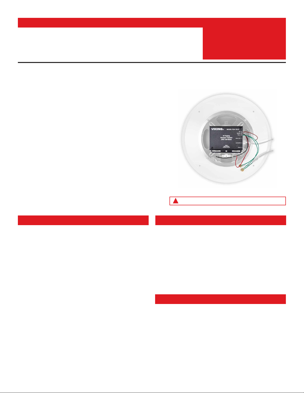
The PSA-TB-IP Speaker Adapter with Talk-Back quickly converts any 8 Ohm, 25V
or 70V analog paging speaker into a SIP endpoint paging speaker. The microphone
enables talk-back and also monitors room noise to automatically increase the
speaker volume when necessary. After a quick conversion, the speaker can be
used for: standard one-way SIP endpoint paging, two-way conversations via SIP
endpoint paging, one-way multicast paging, and making standard or emergency
two-way SIP calls initiated from the optional auxiliary switch input.
The compact chassis of the PSA-TB-IP can be mounted magnetically to the back
of an analog speaker magnet, or use the included screws to attach the unit to the
25/70V transformer mounting holes on the speaker frame. Installation is easy -
mount the microphone behind the speaker grill, attach the wires, and then connect
a CAT5/6 cable from your PoE switch.
An optional auxiliary switch input allows a hard wired button or switch to initiate a
SIP call. The button can be mounted on the wall or concealed under a desk, etc. A
momentary button press will initiate a standard call, while holding the button for 3
or more seconds will initiate an emergency call.
The PSA-TB-IP features a high efficiency 6 Watt class D amplifier capable of
driving up to six 8 Ohm analog paging speakers. This allows you to use a single
PSA-TB-IP to cover up to six speaker paging zones with approximately 1 Watt of
paging power per speaker.
• Amplified SIP endpoint or multicast IP paging for: Schools, Hospitals,
Retail Stores, Office Spaces, etc.
• Provide background music and sound masking
• Make standard and/or emergency SIP phone calls via handsfree talk-
back speaker
• Background music and emergency calls for: Elevator applications,
Retail Stores, Office Spaces, etc.
Convert any 8 Ohm, 25V or 70V Analog Paging Speaker to an IP Speaker for SIP
Endpoint Paging, Multicast Paging and Making Standard or Emergency SIP Calls
Applications
Installation requires a Network Administrator / IT Technician
!
PRODUCT
MANUAL
Designed, Manufactured and Supported in the USA PSA-TB-IP
IP Paging Speaker
Adapter with Talk-Back
April 15, 2021
SECURITY & COMMUNICATION
VIKING
Features
Typical installation example shown above speaker not included

2
VoIP SIP System Compatibility
For compatibility and vendor specific detailed configuration instructions, see the Viking VoIP
SIP System Compatibility List, DOD 944. To open and download this PDF file:
1. Go to www.vikingelectronics.com
and enter 944 in the search box
2. Click Application Note (DOD 944)
to open and download the PDF
Scan the QR code below to open
and download the Viking VoIP
SIP System Compatibility List - OR -
Important: Exclusion from this list means only that compatibility has not been verified, it does not mean
incompatibility. If you have questions, please call Viking Electronics at 715-386-8861.
Note 1: Mount the PSA-TB-IP close to where
the other speakers are installed to minimize the
speaker wire run lengths.
Note 2: Using half the recommended distance
or half as many speakers per run will keep the
volume lost limited to 3db.
Note 3: Doubling up the wires will allow double
the length, or reduce the amount of volume
loss.
Note 4: Heavier gauge wire, fewer speakers
per run, and shorter runs will all minimize
volume loss.
#16
#18
#20
#22
#24
12345
2,000'
1,250'
800'
500'
315'
1,000'
625'
400'
250'
155'
665'
420'
265'
165'
105'
500'
315'
200'
125'
80'
400'
250'
160'
100'
60'
Wire Gauge Size
Number of 8 Ohm Speakers on
Each of the Two Wire Runs
Maximum recommended length (in feet) for the number of 8 Ohm speakers on a wire pair to maintain
a volume loss of less than 5dB. Once the length limit has been reached for the wire gauge used, if
additional speakers are needed, start back at the PSA-TB-IP with a 2nd parallel wire run. If the length
limit is reached again, start a 3rd run, etc. See DOD 895 for an example.
Managing Power Losses

3
Definitions
Client: A computer or device that makes use of a server. As an example, the client might request a particular file from the server.
DHCP: Dynamic Host Configuration Protocol. In this procedure the network server or router takes note of a client’s MAC address and
assigns an IP address to allow the client to communicate with other devices on the network.
DNS Server: A DNS (Domain Name System) server translates domain names (ie: www.vikingelectronics.com) into an IP address.
Ethernet: Ethernet is the most commonly used LAN technology. An Ethernet Local Area Network typically uses twisted pair wires to
achieve transmission speeds up to 1Gbps.
Host: A computer or device connected to a network.
Host Name: A host name is a label assigned to a device connected to a computer network that is used to identify the device in various
forms of network communication.
Hosts File: A file stored in a computer that lists host names and their corresponding IP addresses with the purpose of mapping addresses
to hosts or vice versa.
Internet: A worldwide system of computer networks running on IP protocol which can be accessed by individual computers or networks.
IP: Internet Protocol is the set of communications conventions that govern the way computers communicate on networks and on the
Internet.
IP Address: This is the address that uniquely identifies a host on a network.
LAN: Local Area Network. A LAN is a network connecting computers and other devices within an office or building.
Lease: The amount of time a DHCP server reserves an address it has assigned. If the address isn’t used by the host for a period of
time, the lease can expire and the address can be assigned to another host.
MAC Address: MAC stands for Media Access Control. A MAC address, also called a hardware address or physical address, is a unique
address assigned to a device at the factory. It resides in the device’s memory and is used by routers to send network traffic to the correct
IP address. You can find the MAC address of your PSA-TB-IP speaker printed on a white label on the side of the chassis (see page 4).
Router: A device that forwards data from one network to another. In order to send information to the right location, routers look at IP
Address, MAC Address and Subnet Mask.
RTP: Real-Time Transport Protocol is an Internet protocol standard that specifies a way for programs to manage the real-time transmission
of multimedia data over either unicast or multicast network services.
Server: A computer or device that fulfills requests from a client. This could involve the server sending a particular file requested by the
client.
Session Initiation Protocol (SIP): Is a signaling communications protocol, widely used for controlling multimedia communication sessions
such as voice and video calls over Internet Protocol (IP) networks. The protocol defines the messages that are sent between endpoints,
which govern establishment, termination and other essential elements of a call.
Static IP Address: A static IP Address has been assigned manually and is permanent until it is manually removed. It is not subject to the
Lease limitations of a Dynamic IP Address assigned by the DHCP Server. The default static IP Address is: 192.168.154.1
Subnet: A portion of a network that shares a common address component. On TCP/IP networks, subnets are defined as all devices
whose IP addresses have the same prefix. For example, all devices with IP addresses that start with 100.100.100. would be part of the
same subnet. Dividing a network into subnets is useful for both security and performance reasons. IP networks are divided using a subnet
mask.
TCP/IP: Transmission Control Protocol/Internet Protocol is the suite of communications protocols used to connect hosts on the Internet.
TCP/IP uses several protocols, the two main ones being TCP and IP. TCP/IP is built into the UNIX operating system and is used by the
Internet, making it the de facto standard for transmitting data over networks.
TISP: Telephone Internet Service Provider
WAN: Wide Area Network. A WAN is a network comprising a large geographical area like a state or country. The largest WAN is the
Internet.
Wireless Access Point (AP): A device that allows wireless devices to connect to a wired network using Wi-Fi, or related standards. The
AP usually connects to a router (via a wired network) as a standalone device, but it can also be an integral component of the router itself.
Wireless Repeater (Wireless Range Extender): takes an existing signal from a wireless router or access point and rebroadcasts it to
create a second network. When two or more hosts have to be connected with one another over the IEEE 802.11 protocol and the distance
is too long for a direct connection to be established, a wireless repeater is used to bridge the gap.
4
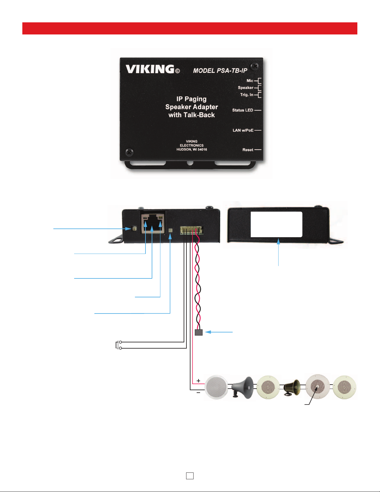
Features Overview
Connect to an optional Momentary Switch
to initiate outbound calls or answer
inbound ringing SIP calls (not included)
Trigger
Input Microphone: Omni-directional microphone with
doubleback tape for mounting behind speaker grille.
Front View
MAC Address Label: The MAC
address is a unique 12 digit number
used by routers to send network
traffic to the correct IP address.
Side Views
Reset Switch:
See page 9, section D and E.
PoE LAN Port 10/100, PoE Class 3 (<13 Watts):
Connect to your LAN via RJ45 plug and CAT5 or
greater twisted pair wire.
Yellow Network Status LED: Lights steady to indicate
power and data link. Blinks to indicate network activity.
Green Unit Status LED
40AE
Speaker
Out
30AE 25AE 35AE
300AE
Volume Control
30AE
See MANAGING POWER LOSS section on page 2 of Product Manual.
Red Call/Status LED: Flashes
during dialing, then lights steady
when answered.
MAC:
18E80FXXXXXX
asdesaxtff
Drive up to (6) Analog Speakers
(Viking Models shown, not included, see DOD 497 and 498)
5
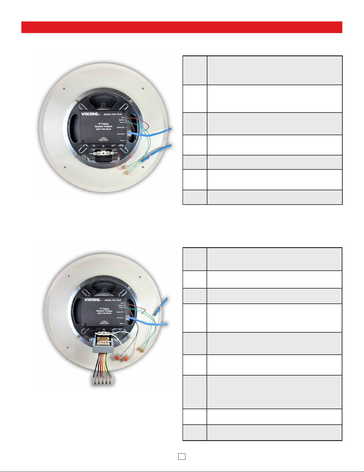
Mounting and Wiring the PSA-TB-IP Paging Speaker Adapter
A. 8-Ohm Speaker Conversion
Step 1.
Disconnect existing speaker connections and remove ceiling tile
with speaker (suspended ceiling) or remove speaker from
drywall. Remove four speaker mounting nuts and remove
speaker from grill.
Step 2.
Magnetically attach the PSA-TB-IP to the back of the speaker
magnet. Alternatively, the PSA-TB-IP can be attached to the
70V transformer mounting holes in the speaker frame with
provided screws.
Step 3.
Clean back center area of the speaker grill with alcohol where
mic will be mounted. Remove release liner from mic and adhere
it to speaker grill centering over a single centered grill hole.
Step 4.
Carefully route mic wires out from under speaker (Making sure
mic wires do not make contact with speaker cone) then reattach
speaker to grill.
Step 5. Attach red and black wires from PSA-TB-IP “Speaker” output
to the speaker terminals.
Step 6.
Attach wires from optional “Call” switch to the two green “Trig.
In” wires on the PSA-TB-IP using provided butt connectors.
Step 7. Attach a Cat5 or higher cable to the PSA-TB-IP LAN w/POE
port. See Typical Installation section for details.
B. 25V or 70V Speaker Conversion
Step 1.
Remove ceiling tile with speaker (suspended ceiling) or
remove speaker from drywall and disconnect the cable
connected to the transformer input wires.
Step 2. Cut the transformer output wires leaving excess wire for the
speaker wire connections. Strip wire ends back 3/8 inch.
Step 3. Remove four speaker mounting nuts and remove speaker from
grill.
Step 4.
Magnetically attach the PSA-TB-IP to the back of the speaker
magnet. Alternatively, the PSA-TB-IP can be attached to the 70V
transformer mounting holes in the speaker frame with provided
screws.
Step 5.
Clean back center area of the speaker grill with alcohol where
mic will be mounted. Remove release liner from mic and adhere
it to speaker grill centering over a single centered grill hole.
Step 6.
Carefully route mic wires out from under speaker (Making sure
mic wires do not make contact with speaker cone) then reattach
speaker to grill.
Step 7.
Cut off the terminals from the PSA-TB-IP’s red and black
speaker output wires and strip wire ends back 3/8 inch. Attach
red and black wires from PSA-TB-IP “Speaker” output to the
speaker wires using provided lever connectors. Note: Third lever
position is used to connect additional speakers.
Step 8. Attach wires from optional “Call” switch to the two green “Trig.
In” wires on the PSA-TB-IP using provided butt connectors.
Step 9. Attach a Cat5 or higher cable to the PSA-TB-IP LAN w/POE
port. See Typical Installation section for details.
6
• IBM compatible personal computer with:
Windows 7, 8 or 10
• Adobe Acrobat Reader 8 or higher
• PSA-TB-IP hardware
PC Requirements
PC Programming
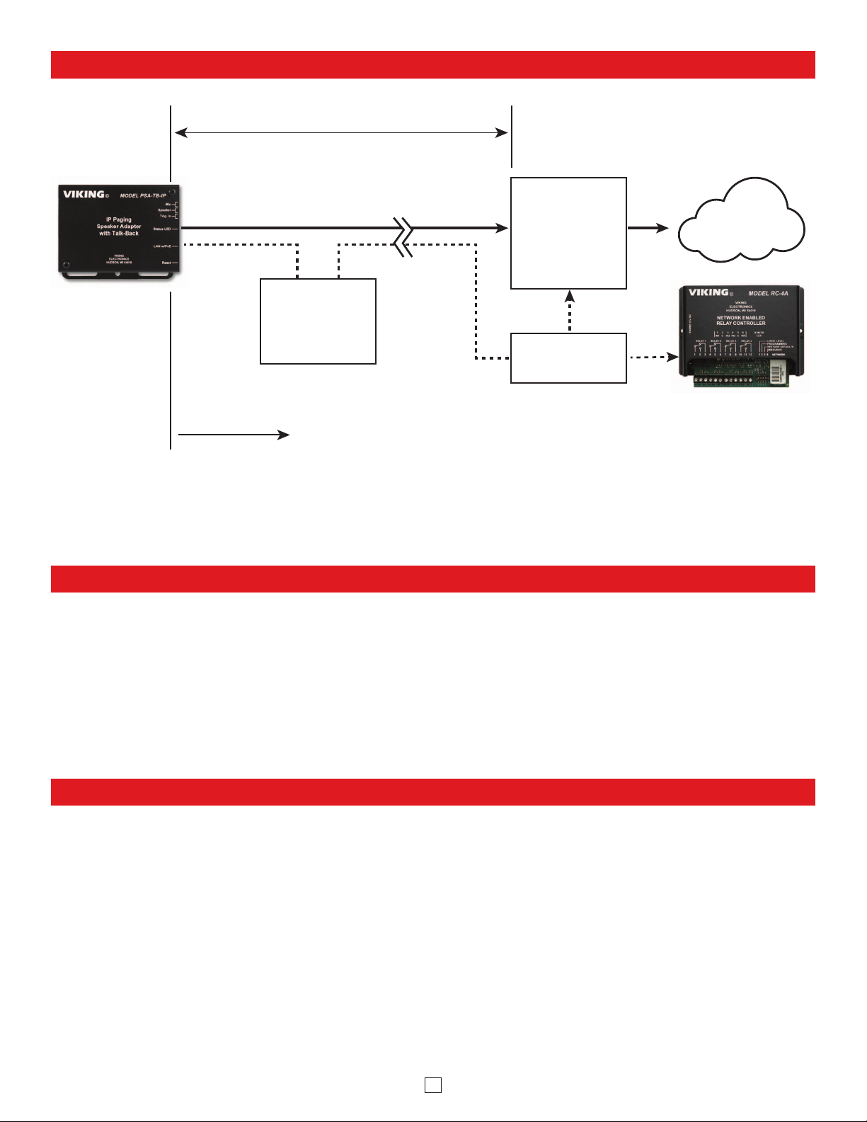
Typical Installation on SIP Based VoIP Phone System
SIP VoIP PBX
or
PC with
SIP Server
Software
100m (328 ft) maximum*
Viking
supplies
Customer’s
Responsibility
Internet
10/100 Mbps
Maximum
Viking
PSA-TB-IP
* Note: A PoE extender can be used for an additional 100 meters per extender. For longer
runs (up to 2 km / 1.2 miles) a ethernet to fiber media converter can be used.
Optional
PoE Injector
(If VoIP PBX does
not have PoE)
Optional
Switch / Hub
Optional Viking model
RC-4A Secure Remote
Relay Controller, see
page 23 (DOD 582)
(Extends range of cable, keeps
1 Gbps network speed for other
equipment on network)
• Available LAN with PoE (class 3, <13 Watts)
• Ethernet cable (CAT5 minimum)
• 1 MB
minimum free hard drive space for installation
• 16MB of free physical RAM
Download and install the programming software
1. Go to www.vikingelectronics.com and enter PSA-TB-IP in the search box
2. Click PSA-TB-IP in the search results
3. Scroll down the page to Downloads, click IP Programming Software
4. Install the programming software by saving or opening the file and then clicking on setup Viking IP
Programming.exe
5. Follow the prompts on your screen to complete software installation
6. To start the Viking IP Programming application, click on the Viking IP Programming icon on your desk top.
The main screen will appear, allowing the user to program any PSA-TB-IP connected to that LAN.
Note: PC must be connected to the same LAN as the PSA-TB-IP.
7
A. Connect / Disconnect
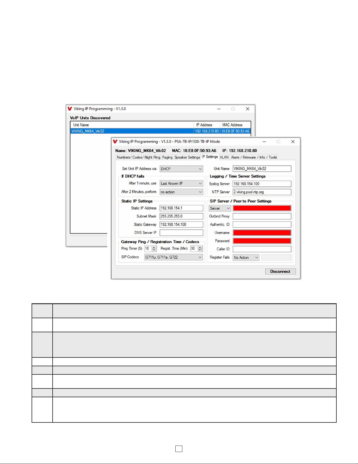
Open the “Viking IP Programming” software on the PC and the start screen shown below will appear. Any Viking IP speakers that
are connected to the network will appear on the list. Simply select the PSA-TB-IP on the list and click on the “Connect” button at the
bottom or double click the selected speaker. If no username and password have been programmed and the security code of the
selected unit is still set to default (845464), the PC software will not require entering a username, password or security code to
connect to the PSA-TB-IP. If the PSA-TB-IP has been programmed with a username and password, a pop up window will ask for
the username followed by the password. If the unit’s security code has been changed from “845464”, it will then prompt for the correct
security code. PSA-TB-IP’s have a default name of “VIKING_MK64_Vik02”, so if many PSA-TB-IP’s are connected to the same
network and all have the default name, MAC addresses must be used to identify each PSA-TB-IP.
When finished programming, click the “Disconnect” button at the bottom. Closing the program will also automatically disconnect the unit.
B. Configuring the PSA-TB-IP Network Settings
Step 1. Open the “Viking IP Programming” software on a windows PC that is connected to the same LAN as the PSA-TB-IP speaker to be
programmed.
Step 2. The window in the upper left corner of the menu will show you each PSA-TB-IP speaker that is connected to that LAN. Select the unit
with the same MAC address shown on the label located next to the Ethernet connector on the PSA-TB-IP speaker.
Step 3.
Click on the “connect” button. A default PSA-TB-IP has no username or password programmed, the security code is set to “845464”
and when configured this way, you are instantly connected to the PSA-TB-IP. If the PSA-TB-IP has been programmed with a
username and password, a pop up window will ask for the username followed by the password. If the unit’s security code has been
changed from “845464”, it will then prompt for the correct security code, then click “retry”.
Step 4. The program will then read and display the PSA-TB-IP speaker’s IP and programming settings.
Step 5. Click on the “IP Settings” tab.
Step 6. Select the appropriate value Static IP Settings or DHCP for “Set Unit IP Address via”. Note: Changing the IP address will cause you to
have to reconnect to the unit. Enter the values for the fields in “if DHCP fails” or “Static IP Settings” as needed.
Step 7. Set the “Unit Name”, “Logging / Time Server Settings” as needed.
Step 8.
Select Peer-Peer in the “SIP Server / Peer to Peer Settings” to use the unit in Peer to Peer mode or for Multicast paging only. Select
Server to register with a SIP registrar server and fill in the “Outbnd Proxy” (SIP Outbound Proxy Server Address, “ip:port”), “Authentic. ID”
(SIP Authentication ID), “Username” (SIP Username, <string>), “Password” (SIP Password), and “Caller ID” (SIP Caller ID) with values
from your VoIP provider. Required fields will be red when the unit is not registered.
8
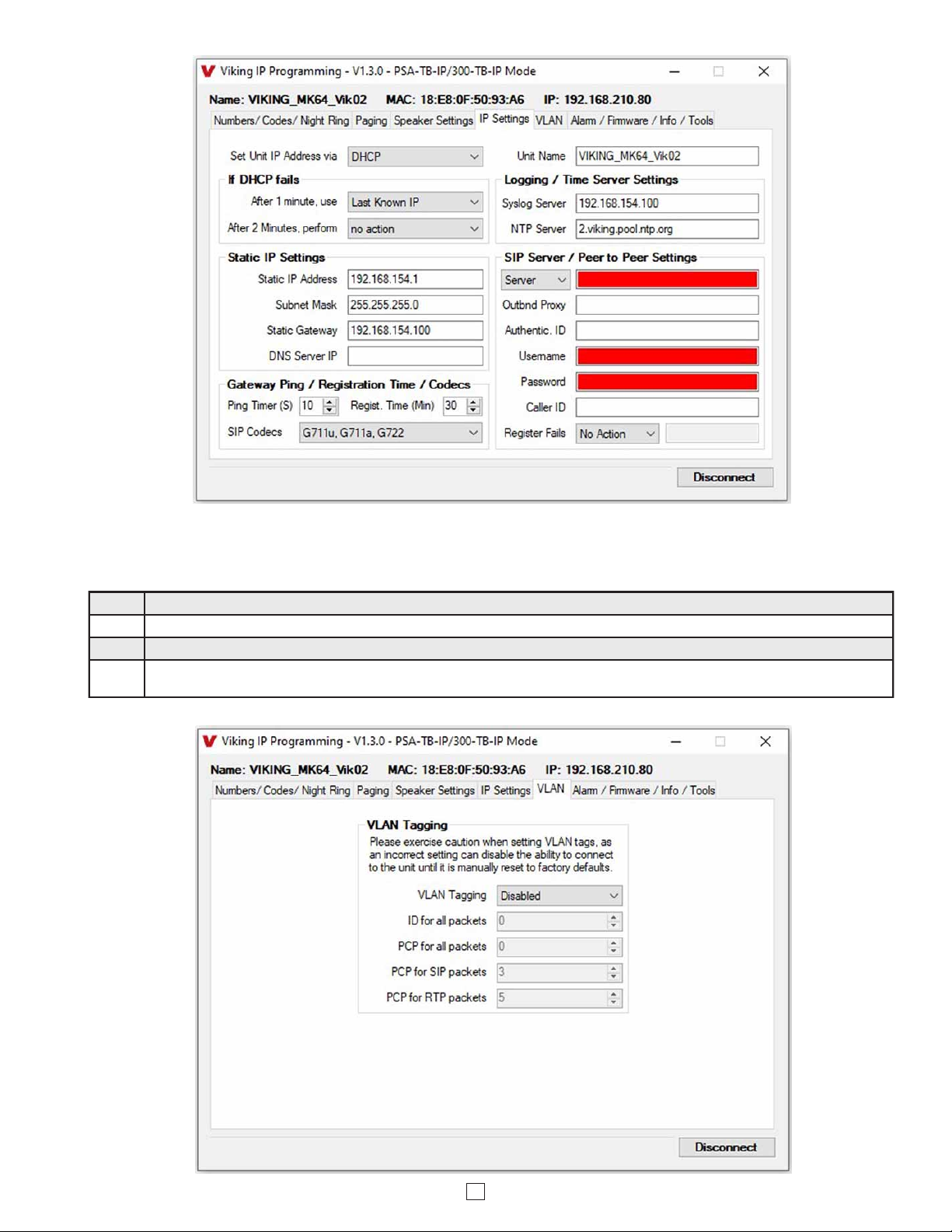
Step 1. Click on the “VLAN” tab.
Step 2. Disable or enable VLAN tagging by setting the value of “VLAN Tagging”.
Step 3. Set the VLAN tag ID by selecting an integer (1 to PSA-94) in “ID for all packets”.
Step 4. Set the Priority Code Point (PCP) value for all not SIP and RTP packets in the “PCP for all packets” input (0 is default, priorities are
from low to high: 0, 1, 2, 3, 4, 5, 6, 7). Set the “PCP for SIP packets” (3 is default). Set the “PCP for RTP packets” (5 is default).
C. Configuring PSA-TB-IP VLAN Settings
9
Step 1. Power down the PSA-TB-IP speaker by disconnecting the LAN Cable (RJ45 plug).
Step 2. Press and hold the Reset button, then reconnect the LAN Cable (RJ45 plug).
Step 3.
Continue to hold the Reset button until you hear a single beep, silence and then 2 beeps (approximately 11 seconds). Then release
the button. The LED will remain off for 5 seconds, light steady for 3 seconds, flash slowly for 3 seconds then fast flash (after the 2
beeps), indicating when to release the button.
Step 4. The security code is now reset to 845464 (factory default).
Step 5. You can now enter programming by following the steps in section A.
D. Manually Resetting the Security Code to Enter Programming
E. Manually Resetting All Network Parameters to Factory Default
Step 1. Power down the PSA-TB-IP speaker by disconnecting the LAN Cable (RJ45 plug).
Step 2. Press and hold the Reset button, then reconnect the LAN Cable (RJ45 plug).
Step 3.
Continue to hold the Reset button until you hear a single beep, silence and then 2 beeps (approximately 11 seconds). Continue to
hold reset button until you hear 4 more beeps (approximately 6 seconds later), then release the button. The LED will remain off for 5
seconds, light steady for 3 seconds, flash slowly for 3 seconds (two beeps), fast flash for 6 seconds (4 beeps), then light steady
indicating when to release the button.
Step 4. You can now enter programming by following the steps in section A.
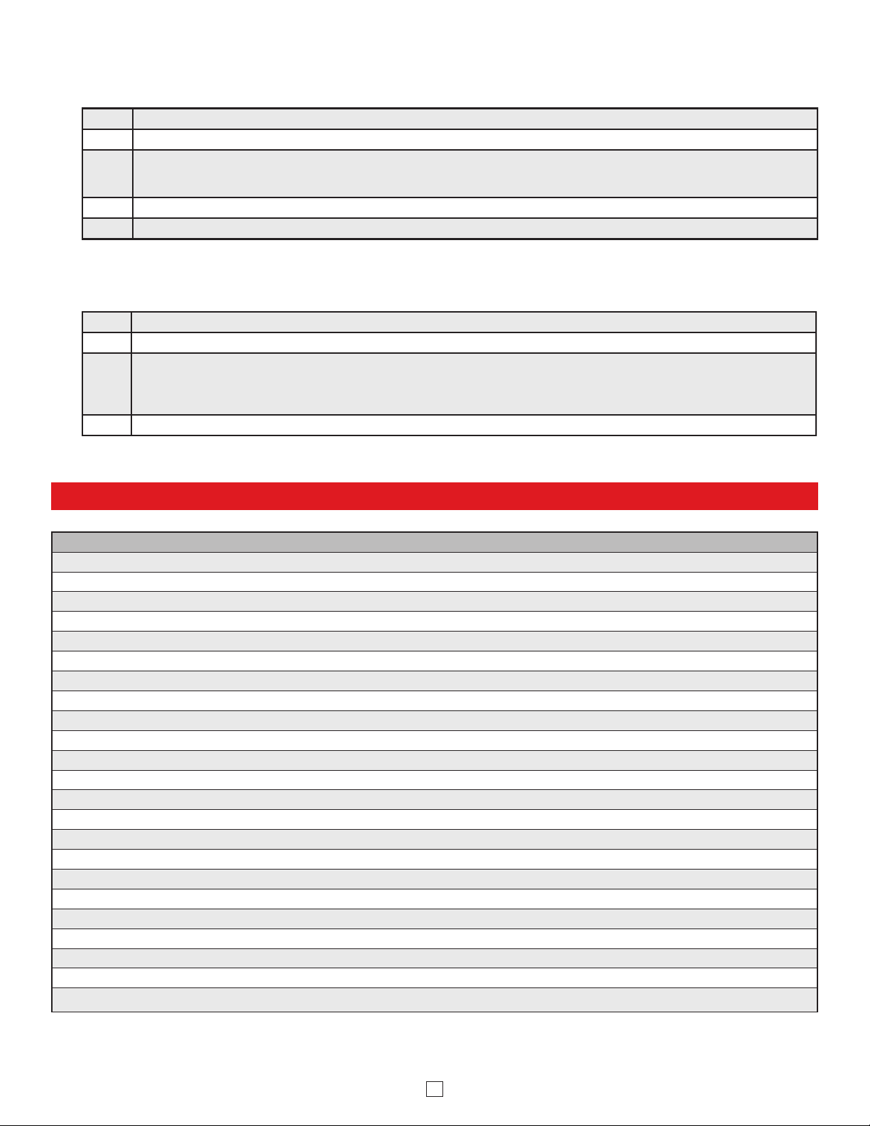
Programming Features Index
DESCRIPTION Section Page
Connect / Disconnect A 7
VLAN Settings C 8
Unit Name 1 10
SIP Server 2 10
Peer to Peer Settings 3 10
Outbound Proxy 4 11
Authentication ID 5 11
Register Fails (Re-Resolve or Alternate Server) 6 11
Pre Page Tone 7 11
Multicast Page Type 8 11
Multicast Page Time Out (1 - 255 seconds, factory set to 180 seconds) 9 11
SIP Page / Call Priority VS Multicast 10 12
Multicast Paging (Standard or Polycom, factory set to Standard) 11 13
Multicast Paging Volume (0 - 19, factory set to 1) 12 13
Emergency Phone Number and Non-Emergency Phone Number 13 14
Security Code (factory set to 845464) 14 14
ID Number 15 14
Access Code (1 - 6 digits, blank = Disabled, factory set to 123456) 16 14
Night Ring Timed Operation 17 14
Time Zone Settings / Daylight Saving Time 18 14
External Relay (factory set to Disabled) 19 15
Ext Relay Mode
(Door Strike, Outbound Call, Phone or Paging, Doorbell, Ring, Ring Flash, factory set to Door Strike)
20 15
Ext Relay Activation Command ( 1 or 2 digits, factory set to QQ) NOTE: Relay Mode must be set to Door Strike.
21 15
Note:
This procedure will not erase a username and password used to access the PSA-TB-IP program mode. Only the security code is set to default.
Note: This procedure will erase a username and password that are used to access the PSA-TB-IP program mode.

10
Programming Features Index
DESCRIPTION Section Page
Ext Relay Activation Time (0.5 - 99 seconds, factory set to 5 seconds) 22 16
Ext Relay Buzz Volume (1 - 3 or Disabled, factory set to 3) 23 16
Ext Relay Latch Commands (Enabled or Disabled, factory set to Enabled) NOTE: Relay Mode must be set to Door Strike 24 16
Panic Button mode (Enabled or Disabled, factory set to Disabled) 25 16
Speaker Mode (ON, OFF / Silent Monitor, or OFF until Answered, factory set to ON) 26 16
Speaker Volume (0 - 19, factory set to 1) 27 16
Ring Volume (0 - 19, factory set to 5) 28 17
Microphone Volume (0 - 9, 0 = Auto, factory set to 5) 29 17
Talk/Listen Delay (VOX) (0.1 - 0.9 seconds, factory set to 0.5 seconds) 30 17
In-Band Audio Call Progress (Enabled or Disabled, factory set to Enabled) 31 17
In-Band Audio Detect Sensitivity (1 - 9, 1 = minimum, 9 = maximum, factory set to 5, power cycle unit after setting) 32 17
Redial Count (1 - 9 or Disabled, factory set to Disabled) 33 17
SIP Page / Call Length Time Out (Disabled or 1 - 9 minutes, factory set to 3 minutes) 34 17
Inbound Call Mode (Disabled, Auto Answer, Auto Answer-Secure, Ring, or Ring with AGC, factory set to Auto Answer) 35 18
Ring Cadence (factory set to Normal Ring = 2 seconds ON, 4 seconds OFF) 36 18
Redial on Ring No Answer (Disabled or 1-9 rings, factory set to 7) 37 18
Redial on Busy (Disabled or Enabled, factory set to Enabled) 38 18
Mute Current / Next Alarm 39 19
Permanent Alarm Mute 40 19
Programming Username and Password 41 19
IP Firmware 42 19
Unit Firmware 43 20
Import / Export 44 20
Clear Speaker Settings 45 20
Clear IP Settings 46 20
Diagnostics (used to check microphone, speaker, and external relay operation) 47 20
3. Peer to Peer Settings
2. SIP Server
When set to Peer to Peer mode, a SIP server is not used. The unit should be programmed with a static IP address and
username, a password is not used. Caller ID can be programmed if needed. Simply call the unit by entering the
programmed “[email protected]...(static IP address for the unit)”. The static IP address is normally programmed into
a page button on the VoIP telephones. NOTE: Peer to Peer mode does not affect multicast paging.
1. Unit Name
Up to a 30 character unit name can be assigned to the PSA-TB-IP being programmed.
Programming Features
Enter the IP address or URL of your SIP server or service provider in this field. The SIP server IP address is limited to
74 characters. Note: If an alternate SIP server IP address is programmed, the IP address for the SIP server and
alternate SIP server will be limited to 31 characters. Note: If outbound proxy is not required, enter the SIP server IP
address into the Outbnd Proxy field.
11
6. Register Fails (Re-Resolve or Alternate Server)
4. Outbound Proxy
If your SIP provider requires an outbound proxy IP address enter it in the “Outbnd Proxy” field. If outbound proxy is not
required enter the SIP sever IP address into the “Outbnd Proxy” field. NOTE: If not required, this field must match your
SIP server IP address.
5. Authentication ID
If your SIP provider requires Authentication ID, enter it in the “Authentic. ID” field. If Authentication ID is not required,
leave this field blank.
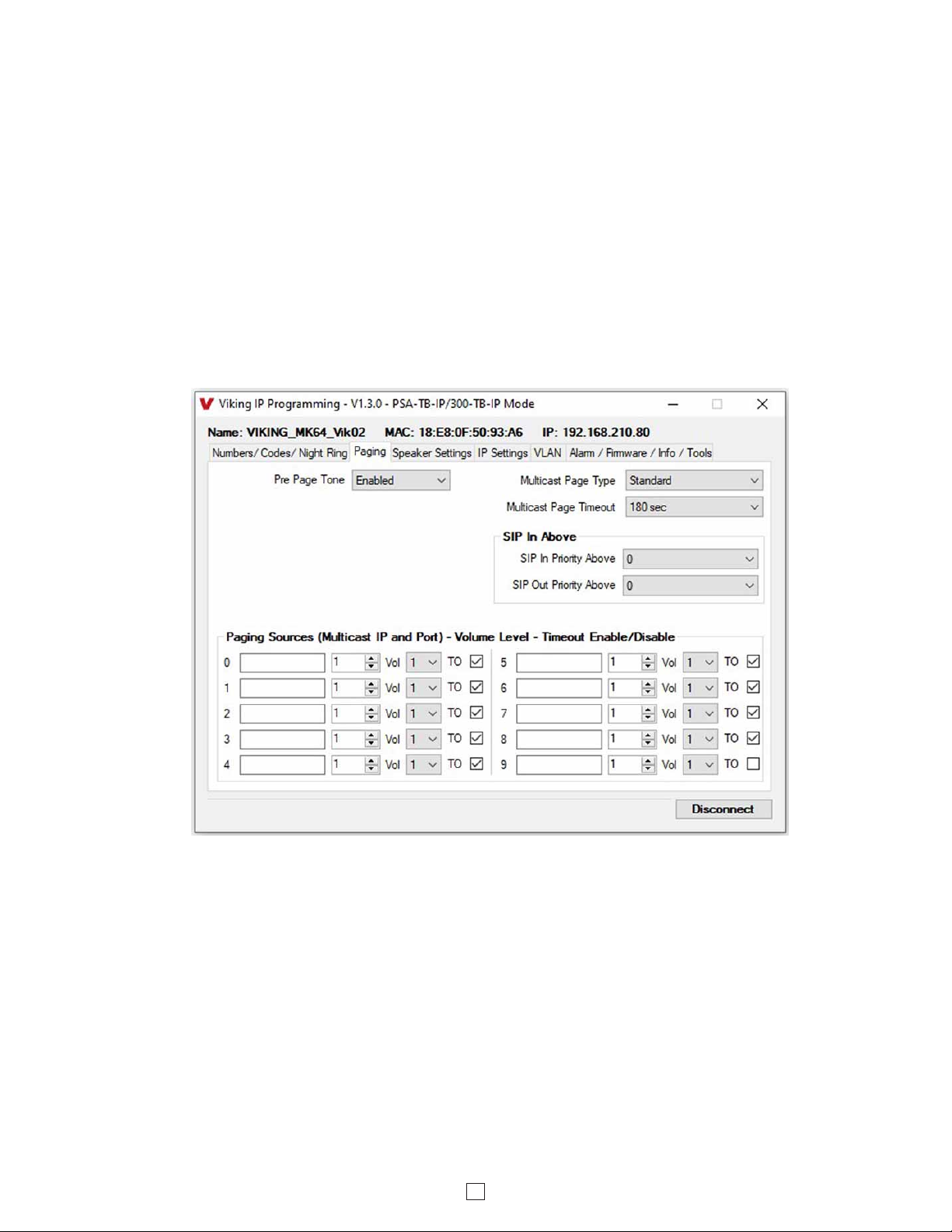
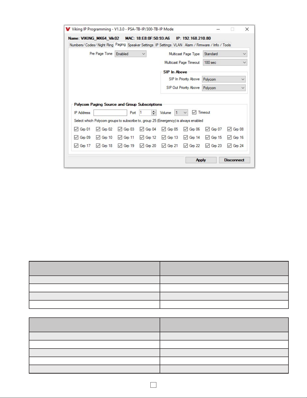
Select Standard or Polycom as the source of multicast paging. If Polycom is selected as the source, the screen will
change to show its options (see next page). For Details see #11 on Page 13.
Factory Setting: Standard (shown above)
7. Pre Page Tone
When enabled, a short beep will be heard prior to SIP or Standard Multicast paging audio. The volume of the Pre Page
Alert Tone will match the volume setting of the SIP or Standard Multicast page. Factory Setting: Enabled
When registered to a SIP server in the event that registration is lost you can program the unit to re-resolve using the
current SIP server IP address or route pages through an alternate SIP server. With Alternate Server selected enter the
IP address of the alternate SIP server in the field next to the Register Fails drop down box. Note: With an alternate
SIP server IP address programmed, the IP address for the SIP server and alternate SIP server will be limited to 31
characters.
8. Multicast Page Type
Standard Multicast Paging Tab
The Multicast Page Length Timeout can be programmed from 1 - 255 seconds in one second increments. The Time
Out can be disabled, allowing any length of page or continuous background music. Only one timeout time can be
programmed for all multicast paging groups. When using standard Multicast Paging, a timeout checkbox can be selected
for each paging group. When using Polycom Multicast Paging, the timeout checkbox enables the timeout globally on
groups 1 through 24. There is no timeout for a page to the emergency group 25.
Factory Setting: 180 seconds
9. Multicast Page Timeout
12
10. SIP Page / Call Priority vs Multicast
Incoming and outgoing non-emergency SIP call audio streams can be programmed to have priority over any of the 10
standard multicast paging groups. Use the “SIP In Above” and “SIP Out Above” drop down menus to select which
multicast groups you want SIP calls to have priority over. “SIP In Above” is to set the priority of incoming SIP pages
and “SIP Out Above” is to set the priority of outgoing non-emergency SIP calls. Regardless of the priorities selected,
outgoing SIP emergency calls have the highest priority and will interrupt any multicast source.
Factory Setting for both: 0 (SIP is highest priority)
When Polycom is selected as the Multicast Page Type, the “SIP In Above” and “SIP Out Above” priorities can be set to
“Poly” or “None”. See the following tables for the order of priorities with each setting. As shown, outgoing SIP
emergency calls have the highest priority and Polycom Group 25 multicast has the second highest priority. The priority
options allow you to determine the priorities for Polycom Groups 1 through 24 multicast signals, SIP paging and non-
emergency outbound SIP calls. Factory Setting for both: Poly
Paging Priorities (SIP In Above and SIP Out Above
both set to “Poly”)
Paging Priorities (SIP In Above and SIP Out Above
both set to “None”)
Emergency Outbound SIP Calls Emergency Outbound SIP Calls
Polycom Group 25 Polycom Group 25
Non-emergency Outbound SIP Calls and SIP paging Polycom Groups 1-24
Polycom Groups 1-24 Non-emergency Outbound SIP Calls and SIP paging
Paging Priorities (SIP In Above set to “None”and SIP
Out Above set to “Poly”)
Paging Priorities (SIP In Above set to “Poly”and SIP
Out Above set to “None”)
Emergency Outbound SIP Calls Emergency Outbound SIP Calls
Polycom Group 25 Polycom Group 25
Non-emergency Outbound SIP Calls SIP Paging
Polycom Groups 1-24 Polycom Groups 1-24
SIP Paging Non-emergency Outbound SIP Calls
Polycom Multicast Paging Tab
13
The volume of each individual standard multicast page can be adjusted from 0 - 19. When polycom paging is used,
the paging volume is set globally for all 25 groups. Factory Setting: 1
12. Multicast Paging Volume
Standard
When using standard Multicast Paging, up to 10 multicast paging groups can be programmed into each PSA-TB-IP
speaker. Each multicast group is defined by a multicast address and port number. Each multicast group is assigned a
priority, allowing simultaneously arriving pages to be serviced based on importance. A timeout check box can be
selected for each paging group. See Multicast Page Timeout under Paging Settings to adjust the timeout from 1 - 255
seconds. Only one timeout time can be programmed for all groups. The volume for each multicast group can be
programmed separately.
Assigning Priority to standard Multicast Paging
The PSA-TB-IP will prioritize simultaneous audio streams according to their priority in the Paging Sources list. Group
0 will have the highest priority while group 9 will have the lowest priority. Group 9 is useful for a low priority stream
such as background music. Group 0 is useful for high priority streams such as emergency messages.
The multicast paging groups can also be used for up to ten different paging zones for receiving audio streams. A paging
zone can consist of one or many PSA-TB-IP multicast speakers. There is no limit to how many speakers can be in a
given paging zone. Each multicast group is defined by a multicast address and port number. Each multicast group is
assigned a priority, allowing simultaneously arriving pages to be serviced based on importance.
Polycom
Polycom IP phones send multicast audio to a specific IP address and port. A total of 25 groups can be used, with
group 25 generally reserved for an emergency broadcast. Set the Multicast Page Type to “Polycom”. The Viking IP
programming page will then show “Polycom Paging Source and Group Subscriptions”. Polycom phones will default
to IP address 224.0.1.116 and port 5001 for multicast. Under “Polycom Paging Source and Group Subscriptions”,
enter the IP address and port you chose in the Polycom IP phone as “Multicast IP address” and “port” (Paging/PTT
Configuration page). Select the paging groups the PSA-TB-IP should subscribe to. Any multicast audio sent to the
correct IP address, port number and a subscribed group will be heard from the Speaker terminals. Group 1 is the
lowest priority and group 25 is the highest. The Volume and Timeout can be selected globally, although the timeout
does not affect group 25. Factory Setting: all Groups selected
11. Standard or Polycom Multicast Paging

14
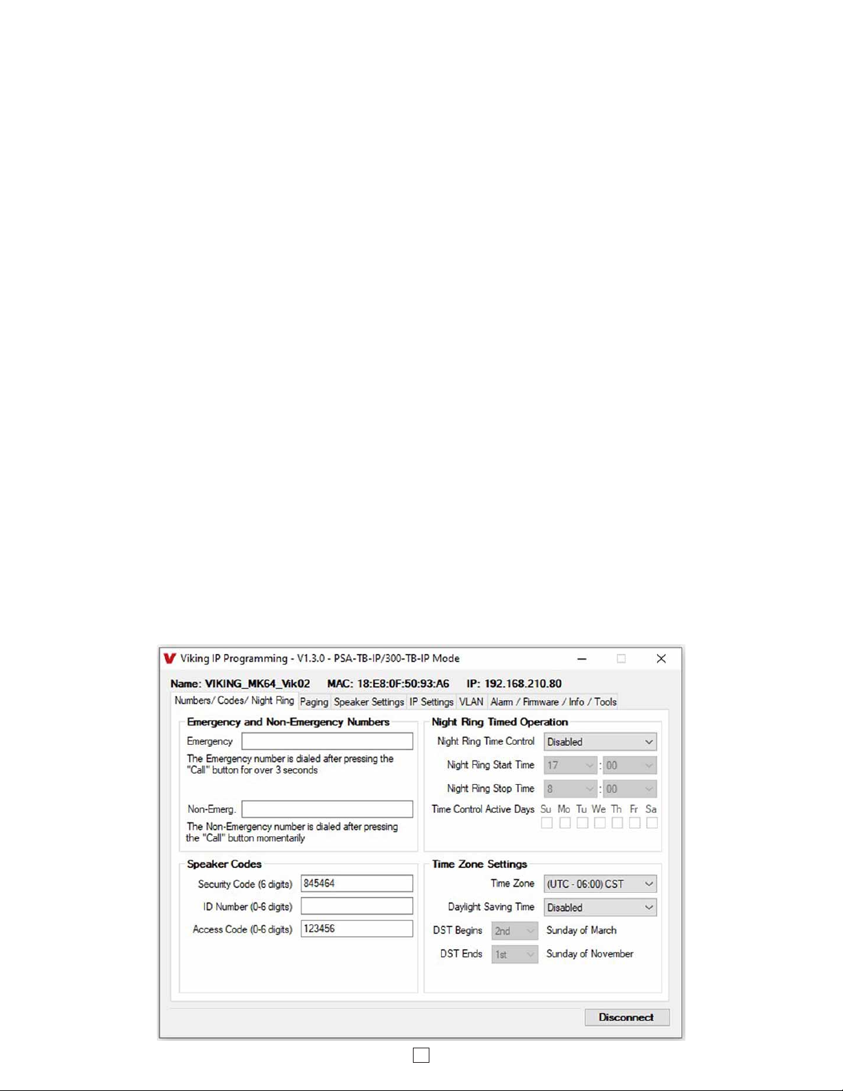
13. Emergency Phone Number and Non-Emergency Phone Number
Note: Up to 125 digits can be stored in the emergency phone number and non-emergency phone number positions.
The phone number called when a hard wired switch is pressed depends on the programming of the “Panic Button
Mode” (“Speaker Settings” tab, See Programming section 25.)
Emergency Phone Number
The number programmed in the “Emergency” field is the telephone or extension number that is dialed for an emergency
call. The PSA-TB-IP will also detect busy and redial the number with “Dial Next Number on Busy” Enabled.
Non-Emergency Number
The number programmed in the “Non-Emerg” field is the telephone or extension number that is dialed for a non-
emergency call. The PSA-TB-IP will also detect busy and redial the number with “Dial Next Number on Busy” Enabled.
The ID Number (1 - 6 digits) is used by emergency personnel to identify the location of the caller and is given out when
the receiving party presses a Q. This ID number is transmitted as In-Band DTMF. This can be cleared out by leaving
the field blank. Factory Setting: (blank)
15. ID Number:
The security code allows the user/installer to program the PSA-TB-IP with a PC and the required ‘Viking IP
Programming” software. If the security code is left as default, the PC software won’t require entering a security code
when connecting to the PSA-TB-IP. It is recommended that the factory set security code be changed. The security
code can be set back to default by holding the Reset button while the PSA-TB-IP powers up. See section D on page
9 for details. It can also be defaulted by connecting to the unit with the IP Programming Software and clicking on the
“Clear Speaker Settings” button on the “Alarm / Firmware” tab. Factory Setting: 845464
NOTE: The security code must be 6 digits and cannot include a Qor #.
14. Security Code
The Access Code is primarily used along with the “Auto Answer Secure” Inbound Call Mode to force inbound SIP page
callers to dial the Access Code before they can make a SIP page. The Access Code also comes into play when using
the relay of the PSA-TB-IP to open a door or gate. When you call the PSA-TB-IP and the unit automatically answers
the call (see Programming section 38), you must dial the Access Code before you are allowed to operate the door
strike relays, as extra security on inbound calls. Once a tenant has entered the correct Access Code, 2 beeps are heard
and the user can now enter any “Operation Commands” (see Operation section D). The Access Code can be disabled
if this basic security is not required. Factory Setting: 123456
Note: The Access Code can be 1 - 6 digits in length and cannot include a Qor # or match the numbers used for the
Security Code.
16. Access Code
17. Night Ring Timed Operation
When Night Ring Timed Operation is enabled, if a SIP call is received during the programmed Start and Stop times,
the PSA-TB-IP will output loud ring on the “Speaker Out” terminals. This is selectable for each day of the week. When
outside of the Night Ring timing window, the Inbound Call Mode setting will determine how SIP calls are handled.
NOTE: For timed Night Ringing the unit must be synced with a time server. If the Night Ringing feature is enabled in
the software you will be asked to use Viking Time Server when changes are applied. The address will be entered by
the software automatically.
18. Time Zone Settings / Daylight Savings Time
When using the Night Ring Timed Operation the PSA-TB-IP must be synced with the network time. Set the Time Zone
Settings to match the settings on the network the unit is connected to for proper timed operation.
15
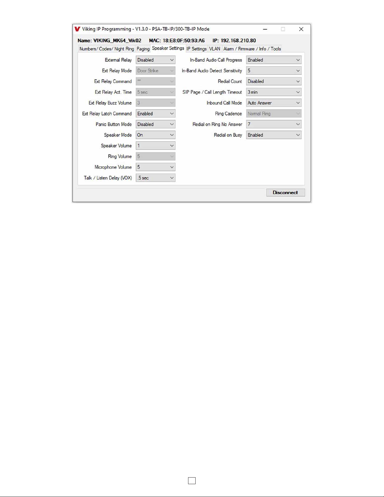
19. External Relay
A Viking remote model RC-4A relay controller can be used to activate up to four external relays (see page 23). With
the external relay set to “Enable EXT 1,2,3,4,+” the PSA-TB-IP will activate an optional RC-4A relay fcontroller.
Factory Setting: Disabled
Door Strike Mode: When programmed for Door Strike Mode the relay is intended for door strike, magnetic lock or
gate control.
Outbound Call Mode: When programmed for Outbound Call Mode the relay will activate continuously for the duration
of any outbound call from the speaker phone.
Phone / Paging Mode: When programmed for Phone/Paging Mode the relay will activate continuously for the duration
of any SIP or multicast page or any inbound or outbound call to or from the speaker phone. This mode is useful for
triggering paging amplifiers, etc.
Doorbell Mode: When programmed for Doorbell Mode the speaker phone will momentarily activate the relay for the
preprogrammed relay activation time on any outbound call from the speaker phone. This mode is useful for activating
a door chime, etc. When activating door chimes, a 0.5 - 1 second relay activation time is recommended.
Ring Mode: When programmed for Ring Mode the relay will continuously activate while the ringing extension is called.
This mode is useful for activating a Viking model SL-2 strobe light, etc.
Ri
ng Flash Mode: When programmed for Ring Flash Mode the relay will momentarily turn on and off in a 400 ms on/off
cadence while the ringing extension is called. This mode is useful for activating a Viking LPL-1 Remote Visual Indicator, etc.
20. Ext Relay Mode
The one or two digit code stored in the Relay Activation Command is the touch tone command that the person being
called must enter on their phone in order to momentarily activate the relay to control a door strike, magnetic lock, gate
controller, or other device. The code can contain the characters 0-9, # or Q. The code cannot match a relay latching
command (Q1, Q0). The code must be entered while the remote phone is communicating with the speaker phone.
Factory Setting: QQ.
21. Ext Relay Activation Command

16
The value stored in the Relay Activation Time is the amount of time the relay will be energized after a correct momentary
touch tone command is entered. This number can range from 0.5 - 99 seconds. This also affects timing in Doorbell
Mode. Factory Setting: 5 seconds
22. Ext Relay Activation Time
The relay activation tone is a buzzing sound that is heard from the speaker when the door strike relay is activated.
After the called party enters the correct relay activation command, the called party will hear 2 short confirmation beeps
and the speaker will output a buzzing sound (relay activation tone) while the door strike relay is activated. The tone
(buzz) length will match the relay activation time up to a maximum of 5 seconds. The tone (buzz) can be programmed
to three different volume settings 1 = Low, 2 = Medium, 3 = High or it can be disabled. When disabled, the confirmation
beeps will not be heard. Factory Setting: 3
23. Ext Relay Buzz Volume
When set to “Enabled” the Operation Commands (Q0 to Q1) to Un-Latch or Latch the relay are enabled. These can be
entered on a inbound call after the access code is dialed (if programmed).
When set to “Disabled” the Operation Commands (Q0 to Q1) to Un-Latch or Latch the relay are disabled. Disabling the
latch commands can be useful in applications where you want to eliminate the possibility of inadvertently entering a
latch command leaving a gate open/closed, etc.
Factory Setting: Enabled
24. Ext Relay Latch Commands
26. Speaker Mode
The Speaker Mode can be set to one of the following three modes. Factory Setting: ON
OFF / Silent Monitoring Mode: In the “OFF” mode the speaker is disabled at all times. However, the speaker can be
enabled after communication has been established by entering touch tone command “9#”. The speaker will remain on for
the duration of the call. When using silent monitor made, do not connect audio to the Line In terminals.
ON: In the “ON” mode the speaker is enabled during In-bound and Out-bound calls.
OFF Until Answered: In the “OFF Until Answered” mode the speaker will remain silent during dialing and will not turn
on until the called party has answered.
Panic Button Mode disabled: Momentarily pressing the hard wired switch will immediately initiate a non-emergency
call. Holding the hard wired switch for three or more seconds will initiate an emergency call. Pressing the hard wired
switch after a call has been initiated will terminate the call.
Panic Button Mode enabled: The Panic Button mode is intended for emergency applications, therefore non-
emergency phone number dialing is disabled. Momentarily pressing the hard wired switch will immediately initiate an
emergency call. Pressing the hard wired switch again after the call has been initiated will not terminate the call. The
Speaker Mode can be set to one of the OFF modes for the Panic Button Mode.
Factory Setting: Disabled
25. Panic Button Mode
The Speaker volume can be set from 0 - 19. 0 = lowest volume setting, 19= highest volume setting. Adjusting this will
set the Speaker volume level for SIP Paging and incoming/outgoing phone calls. This setting does not affect multicast
volume settings. Factory Setting: 1
The Speaker volume can alternatively be set to Auto 0 – 10, 15 or 19. 0 = the lowest automatic volume setting and 10,
15 or 19 = the highest automatic volume setting. With volume set to auto the PSA-TB-IP will use its built-in microphone
to monitor background room noise and automatically increase or decrease the Speaker volume for SIP paging,
incoming/outgoing phone calls and Multicast paging. Note: The minimum volume setting for multicast paging is set
separately per multicast IP address and port. See “Paging” menu in Viking IP Programming.
27. Speaker Volume

17
The microphone volume can be set from 1 - 9, 1 = lowest volume setting, 9 = the highest volume setting. Alternatively
the microphone can be placed in the “Auto” Automatic Noise Cancelling mode. With the mic in the Auto mode, when
background noise increases, the mic gain will automatically decrease. When background noise decreases the mic gain
will automatically increase. The Auto mode is useful in applications where the background noise level can change
drastically. Factory Setting: 5
29. Microphone Volume / Automatic Noise Cancelling Mode
This feature selects switching time between talk and listen modes (VOX switching time). The Talk / Listen Delay can
be programmed from 0.1 - 0.9 seconds. Factory Setting: 0.5 seconds
30. Talk / Listen Delay (VOX)
When set to Ring or Ring with AGC, The PSA-TB-IP will output a loud ring when it is called. The level can be adjusted
from 0 - 19. Factory Setting: 5
28. Ring Volume
The In-Band Audio Call Progress Detection can be set to enabled or disabled. In-Band Audio Call Progress detection
should be enabled in applications where you are making an outbound call through your VoIP phone system and are
relying on In-Band analog audio for ringback or busy detection. Factory Setting: Enabled
31. In-Band Audio Call Progress
The In-Band Audio Detection level (Sensitivity) can be set from 1 to 9,1 = minimum setting, 9 = highest setting.
Increasing or decreasing the sensitivity may be required in applications where you are making an outbound call through
your VoIP phone system and are relying on In-Band analog audio detection. Factory Setting: 5
32. In-Band Audio Detect Sensitivity
33. Redial Count
With the Redial Count disabled, if the PSA-TB-IP speaker is programmed to dial the next number on ring-no-answer
and/or busy signal, the PSA-TB-IP speaker will continuously call its programmed phone number forever until the call
is answered.
The Redial Count is a programmable counter that determines how many times the PSA-TB-IP speaker phone will
redial its emergency phone number or “Non-Emergency” phone number before it stops the dialing process and hangs
up. When the Redial Count has been met, the dialing process stops and the PSA-TB-IP speaker phone hangs up.
Factory Setting: Disabled
This feature selects the maximum length of time that calls can be connected. Programmable in increments of 1 minute
up to a maximum of 9 minutes or disabled. With the call length disabled, the PSA-TB-IP speaker must rely on a call
ended signal, busy signal, Ring No Answer limit, or touch tone # to hang-up. Factory Setting: 3 minutes
34. SIP Page / Call Length Timeout

18
The Inbound Call Mode determines how the PSA-TB-IP handles incoming SIP calls. One option is to generate a loud
ring sound through the speaker. The PSA-TB-IP can also auto answer a SIP call to transmit a page, control the relay
or listen to transmit audio from the microphone. The last option is the silent monitor mode, which allows callers to
listen to the transmit audio from the microphone. The “secure” options for auto answer require the callers to dial the
access code in order to transmit a page or activate the optional RC-4A relays.
Factory Setting: Auto Answer
Disabled: Inbound SIP calls are not allowed.
Auto Answer: Inbound SIP calls are auto answered on the first ring. This can also be used for Silent Monitoring by
changing the speaker mode to “OFF / Silent Monitor”, see page 15. For more security use the Auto Answer Secure
Mode.
Auto Answer Secure: Inbound SIP calls are auto answered and the caller must dial the access code in order to listen
or talk on the unit.
Ring: In the “Ring” mode the speaker phone will not automatically answer an incoming call but will output a loud ring
signal out of the speaker in a factory programmed 2 seconds ON, 4 seconds OFF ring pattern. There are four available
ring cadences.
Ring with AGC: In the “Ring with AGC” mode the speaker phone will not automatically answer an incoming call but
will output a loud ring signal out of the speaker in a 2 seconds ON, 4 seconds OFF ring pattern. The speaker will
automatically increase or decrease the ring volume based on background ambient noise. The call can then be answered
by momentarily pressing the “Trig In” button.
35. Inbound Call Mode
36. Ring Cadence
The Ring Cadence can be programmed to one of four different cadences. Factory Setting: Normal Ring
Normal Ring (single ring: 2 seconds ON, 4 seconds OFF)
Double Ring (double ring: 1 second ON, 0.5 second OFF, 1 second ON, 3.5 seconds OFF)
Short-Short-Long (triple ring: 0.5 second ON, 0.5 second OFF, 0.5 second ON, 0.5 second OFF, 1 second ON, 3 seconds OFF)
Short-Long-Short (triple ring: 0.5 second ON, 0.5 second OFF, 1 second ON, 0.5 second OFF, 0.5 second ON, 3 seconds OFF)
If enabled and a busy is detected, the speaker phone will dial the Emergency phone number. A momentary press of
the “Trig In” button will dial the programmed Non-Emergency phone number. Pressing and holding the “Trig In” button
for 3 or more seconds will dial the Emergency Phone number. Factory Setting: Enabled
38. Redial on Busy
37. Redial on Ring No Answer
If enabled and a ring-no-answer is detected, the speaker phone will dial the next programmed Emergency phone
number or Non-Emergency phone number. A momentary press of the “Trig In” button will dial the Non-Emergency
programmed phone number. Pressing and holding the “Trig In” button for 3 or more seconds will dial the Emergency
Phone number. Factory Setting: 7 (will redial after 7 rings)

19
39. Mute Current / Next Alarm
With Alarm Tones Enabled a network failure alarm will be indicated by providing 3 beeps every 30 seconds. A network
failure indicates the unit is not registered to the SIP server or there is a communication failure with the gateway. The
three beeps can be muted by clicking on “Mute Current / Next Alarm”. The Status LED will continue to flash to assist
troubleshooting. The alarm beeps can also be permanently disabled, see 44. Permanent Alarm Mute.
Factory Setting: Disabled
40. Permanent Alarm Mute
Alarm Tones are disabled by default. To enable alarm tones select “Alarm Tones Enabled”.
41. Programming Username and Password to Restrict Access to Programming
To increase security, a username and password can be programmed to limit access to the PSA-TB-IP using Viking IP
Programming software. When no username and password are programmed and the security code is still set to default
(845464), the PC software will not require a username, password or security code when connecting to the PSA-TB-IP.
If the PSA-TB-IP has been programmed with a username and password, a pop up window will ask for the username
followed by the password. If the unit’s security code has been changed from default (845464), it will then prompt for
the correct security code.
If the username and password are unknown, they can only be erased by resetting all network parameters to default
with the reset button (see section E on page 9). If the username and password are known but you wish to erase them,
that can be accomplished by exporting the data from the PSA-TB-IP (“Alarm / Firmware” tab of Viking IP Programming),
resetting all network parameters to default with the reset button (see section E on page 9) and then importing the data
back into the speaker.
42. IP Firmware
Update IP is currently not available. The ability to update IP firmware will be made available in a later release of Viking
IP Programming software. If an IP firmware update is needed, Viking Technical Support will assist in updating the IP
firmware.

20
43. Unit Firmware
If new PSA-TB-IP firmware is available, after opening the programming software a pop up window will ask if you would
like to update firmware. Another way to update is accomplished by clicking the speaker firmware “Update Unit” button.
You can then browse to the folder that contains the HEX file for updating the unit’s firmware. This method is typically
only used when Viking Technical Support has sent you updated firmware.
44. Import / Export
The Import / Export feature is useful for backing up all the PSA-TB-IP’s programming or for importing programming
when installing multiple units with a majority of the same programming.
Clicking on the “Clear Speaker Settings” button in programming will reset all of the Programming Features back to
their factory default settings. NOTE: This command will not change or reset your IP settings.
45. Clear Speaker Settings
Clicking on the “Clear IP Settings” will reset all of the IP settings back to their factory default settings. This also clears
paging Group settings and Addresses. NOTE: This will not affect any speaker or paging settings.
46. Clear IP Settings
47. Diagnostics
The Diagnostics section in the Viking IP Programming can be used to test the functionality of the mic, speaker and the
optional RC-4A relays.
Table of contents
Other Viking Adapter manuals

Viking
Viking PA-IP User manual

Viking
Viking E-40 Series Instructions for use

Viking
Viking LLA-4 Instructions for use

Viking
Viking DLE-200B Instructions for use

Viking
Viking K-600D Instructions for use

Viking
Viking SO-24A Instructions for use

Viking
Viking LLA-1 User manual

Viking
Viking PSA-IP User manual

Viking
Viking ATA-100 Instructions for use


