2. Calibration
This chapter is divided into calibration protocol and calibration firmware. The protocol can be adapted into
any test or programming tool to support calibration. The AVRISP mkII, JTAGICE mkII, JTAGICE3, and
Atmel-ICE programming tools support the implemented calibration protocol. The usage of these tools to
calibrate a device is described in later sections.
2.1. Calibration Protocol
The protocol for calibration is simple and fast to ensure that it can be used in production environments.
The pins used for programming the device, either the ISP interface or the JTAG interface, are also used
for calibration since they are most likely to be available in a final product (or on the PCB).
Two pins are used for calibration: MOSI and MISO on the ISP interface, or TDI and TDO on the JTAG
interface. To simplify the following explanations, only MOSI and MISO are mentioned, although these can
be replaced with TDI and TDO for the case of the JTAG interface.
The overall concept is that the programming tool generates the calibration clock (C-clock), and the device
uses this as a reference to calibrate its internal RC oscillator. When the device has completed the
calibration it signals “OK” to the programming tool on the MISO line.
The device is responsible for enabling a pull-up on the MOSI line, and the programming tool is
responsible for enabling a pull-up on the MISO line. Unfortunately the programming tool is in many cases
behind level converters, so the device sets also the MOSI line high. This is done to make sure that noise
is unlikely to corrupt the calibration.
The programming tool can use 1024 C-cycles (cycles on the C-clock) as a time-out period, as the
calibration routine is guaranteed to be completed within this number of C-cycles.
2.2. Steps Involved in the Calibration Procedure
1. The programming tool writes the calibration firmware into the device and possibly enables the
MISO pull-up, and releases the reset line. If the JTAG interface is used, the JTAG disable bit in
MCUCSR is set by the calibration firmware in the device. The calibration clock (approximately
32kHz) is applied on the MOSI line by the programming tool.
2. The device enables the internal pull-up on the MOSI line, sets the MISO line high, and starts
listening for the calibration clock on MOSI.
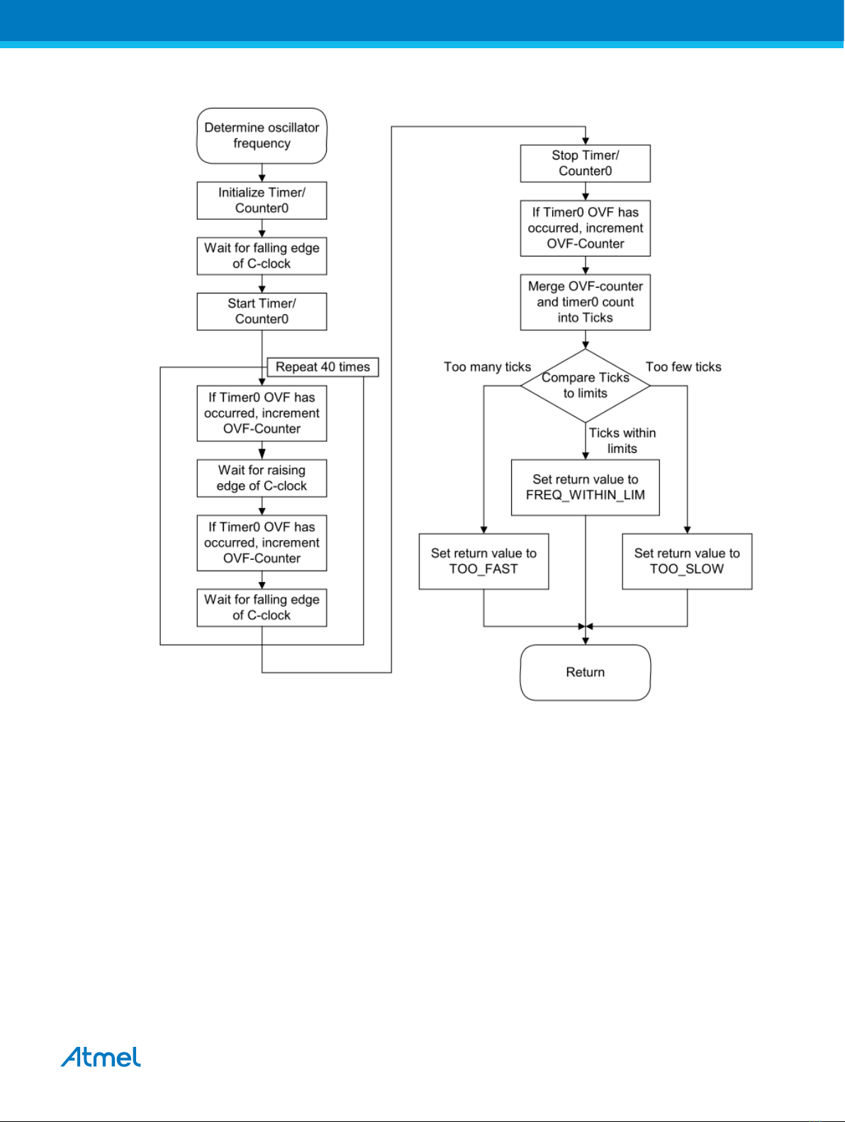
3. When the device detects the calibration clock a binary search is performed to find an OSCCAL
value that meets the criteria of 1% accuracy. If the binary search does not reveal a value that meets
this requirement, the neighboring values of the outcome of the binary search are tested to identify
one that does. If calibration fails the MISO line is set low and program flow goes to step 6.
4. The calibration value is stored in EEPROM (skipped if calibration fails).
5. The MISO line is toggled 8 times/4 cycles by the device. The toggling of the MISO line is performed
on the falling edge of the clock on the MOSI line (C-clock), but 5 to 10 CPU cycles delayed. In the
case of failing calibration the MISO line is not toggled.
6. If necessary, the JTAG interface is re-enabled and the device goes into an infinite loop.
7. If the device does not have an EESAVE fuse, the programmer must read back the calibration byte
from EEPROM, for later restoring when the calibration firmware has been erased from the flash
memory. If the device has an EESAVE fuse, this fuse can be set so that erasing the Flash does not
also erase the EEPROM. It is necessary to copy the calibration byte from EEPROM or FLASH to
Atmel AVR053: Internal RC Oscillator Calibration for tinyAVR and megaAVR Devices [APPLICATION
NOTE]
Atmel-2555H-Internal-RC-Oscillator-Calibration-for-tinyAVR-and-megaAVR-Devices_AVR053_Application Note-09/2016
7