ATN Zebra 12 Instruction Manual

11/2009
1NO 0027FR-01
1NO0027UK-05 revision 08/2015
Lieu-Dit Bacqué, rue André Thévet
47400 FAUILLET - FRANCE
Tel: 33 (0)5 53 79 83 20
Fax: 33 (0)5 53 79 96 90
www.atnplatforms.com
Operator and
Safety Manual
Translation of the original manual

OPERATOR AND SAFETY MANUAL
1NO0027UK-05
ZEBRA 12
2
DISTRIBUTOR’S STAMP

OPERATOR AND SAFETY MANUAL
1NO0027UK-05
ZEBRA 12
3
DANGER
DO NOT USE THIS MACHINE IF YOU
HAVE NOT BEEN TRAINED IN USING IT
SAFELY.
THE TRAINING INCLUDES THE
KNOWLEDGE OF THE WORK
REGULATIONS OF YOUR EMPLOYER,
THE INSTRUCTIONS IN THIS MANUAL
AND CURRENTLY ENFORCED
REGULATIONS ON THIS TYPE OF
MACHINE.
AN UNQUALIFIED OPERATOR IS
EXPOSED AND EXPOSES OTHERS TO
RISKS OF SEVERE OR EVEN LETHAL
INJURY.
DANGER
IN THE WORK MODE, MOVE THE
PLATFORM ONLY ON HARD AND
HORIZONTAL GROUND, WITHOUT ANY
OBSTACLES.
THE 4 WHEELS MUST BE IN
PERMANENT CONTACT WITH THE
GROUND. THE LOAD MUST BE
DISTRIBUTED IN THE PLATFORM, AND
MUST NOT EXCEED THE NOMINAL
LOAD SET BY THE MANUFACTURER,
REGARDLESS OF THE POSITION OF
THE CAGES OR THE ARM.
THE MAXIMUM NOMINAL LOAD IS
INDICATED ON THE MANUFACTURER
PLATE OF THE MACHINE.

OPERATOR AND SAFETY MANUAL
1NO0027UK-05
ZEBRA 12
4
FOREWORD
This manual was written to allow you to properly use and maintain your self-propelled platform.
Carefully read it and understand its content. After reading and understanding all the sections, store
this manual in the document compartment in the platform of the
ZEBRA
.
This platform was designed to offer maximum performance with minimum maintenance. Observing
the maintenance operations will ensure many years of problem-free operation.
In no event does the information presented in this manual replace community, state and local
regulations, nor safety guidelines or clauses of insurance policies.
The manual groups the following main parts:
- conditions for commissioning and using the machine.
- instructions of use of the machine.
This manual presents the main safety rules, as well as important information on the operation of
elevator platforms,
ZEBRA 12
models.

OPERATOR AND SAFETY MANUAL
1NO0027UK-05
ZEBRA 12
5
DESCRIPTION OF THE PLATFORM
This elevator platform is of the self-propelled type, with a chassis in mechanically welded steel.
Movement is ensured by four hydraulic motors via a hydrostatic transmission. Steering is ensured
by a hydraulic jack. The diesel engine coupled to a variable flow pump supplies hydraulic power to
supply the functions of the platform. Electric power supplied by an alternator and a battery at a
total voltage of 12 volts.
In the working mode, the platform must be moved only on compacted and horizontal ground,
void of any obstacle. The wheels must be in permanent contact with the ground. The load must
be distributed in the platform, and must not exceed the nominal load set by the manufacturer,
regardless of the position of the hydraulic boom and telescope. The maximum nominal load is
indicated on the manufacturer plate of the machine.
UPON DELIVERY...
Perform an immediate general check to find anything suspect or abnormal.
Perform each of the following checks (non exhaustive list):
- Motor/backup unit start switches
- Validation pedal
- Emergency stop(s)
- Joystick controlling wheel translation and steering
- Hydraulic boom up/down control switches
- Telescope out/in control switches
- Turret rotation control switches
- Gear selector
- Movement selector, . . .
In case of non-compliance...
Issue a claim immediately, and send a copy to and the carrier.
You can issue a claim up to 48 hours after delivery.
WARNING
DO NOT REPAIR, MODIFY, OR ADJUST
A PART OF THE MACHINE WITHOUT
WRITTEN AUTHORIZATION FROM
ATN. NON COMPLIANCE WOULD
CANCEL THE GUARANTEE

OPERATOR AND SAFETY MANUAL
1NO0027UK-05
ZEBRA 12
6
DANGER
DO NOT USE THIS MACHINE IF YOU
HAVE NOT BEEN TRAINED IN USING IT
ZEBRA 12
DANGER
ALWAYS READ THE OPERATOR AND
SAFETY MANUAL BEFORE USING THE
MACHINE.

OPERATOR AND SAFETY MANUAL
1NO0027UK-05
ZEBRA 12
7
If this platform is involved in an accident, please call your distributor immediately, and provide all
the details on the accident. If the distributor is unknown, or cannot be notified, please contact:
Tel: 33 (0)5 53 79 80 60
Fax: 33 (05) 53 79 96 90
Address: Lieu-Dit Bacqué, rue André Thévet, 47400 Fauillet, France
GUARANTEE
FOR ANY NEW EQUIPMENT, THERE IS NO OTHER GUARANTEE, EXPLICIT OR IMPLICIT,
THAT THE VENDOR GUARANTEE COVERS MATERIAL OR MANUFACTURING FLAWS
WRITTEN IN THE FOLLOWING TERMS:
GUARANTEE ON NEW EQUIPMENT
"The Manufacturer guarantees each new product against any material or manufacturing flaw, his
obligation and liability being limited under this guarantee to repairing or replacing, free of charge
in his factory, any part acknowledged as being faulty in normal use and maintenance, and the
reasonable cost of repair and/or replacement of the said parts within twenty four (24) months
from the initial date of sale (5 years for the structure), leasing with purchase option, provided
equipment start-up by the Distributor was registered with the Manufacturer. In case of lack of
registration with the Manufacturer, the date used as initial date of sale, leasing with purchase
option is the date on which the equipment was shipped from the plant. This guarantee replaces
any other explicit or implicit guarantee and the Manufacturer's liability within this guarantee
excludes shipping or other expenses, or any other liability for direct, indirect or consecutive
damage, as well as any delay due to any flaw. This fact does not extend the period of guarantee
of the machine, nor that of the parts replaced. The guarantee is cancelled in case of use beyond
capacities or in conditions not planned by the Manufacturer, or when using parts not approved
by the said Manufacturer.
THIS GUARANTEE REPLACES EXPRESSLY ANY OTHER EXPLICIT OR IMPLICIT
GUARANTEE, INCLUDING ANY IMPLICIT GUARANTEE OF MERCHANTABILITY OR
PROPER ADAPTATION TO A GIVEN APPLICATION AND ANY OTHER OBLIGATION OR
LIABILITY OF THE VENDOR.
TO THE ATTENTION OF THE CLIENT / USER

OPERATOR AND SAFETY MANUAL
1NO0027UK-05
ZEBRA 12
8
TABLE OF CONTENTS
SECTION 1. GENERAL DESCRIPTION .........................................................................................9
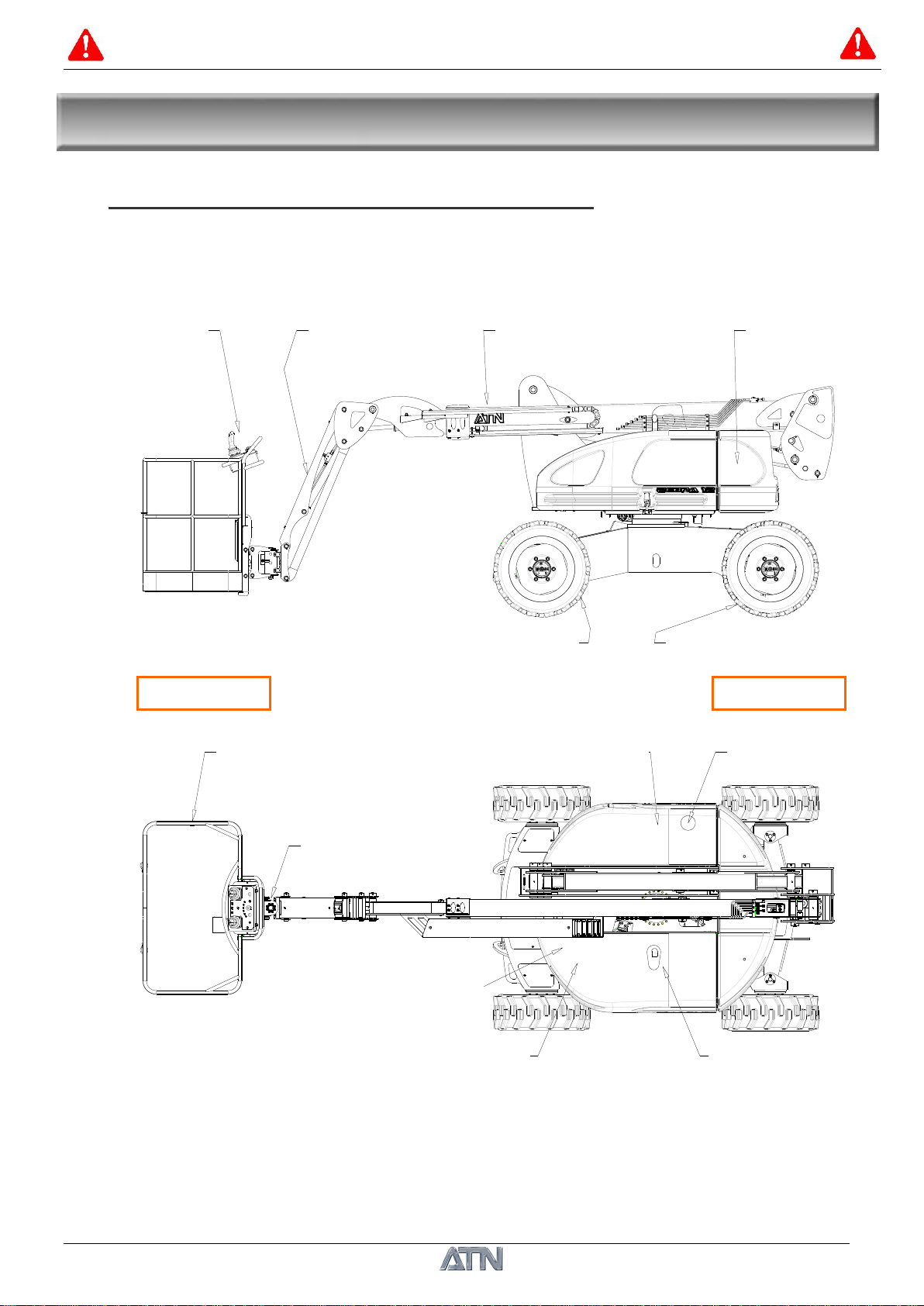
1.1. DESCRIPTION OF THE MACHINE, DIMENSIONS.........................................................................9
1.2. DIAGRAMS OF EVOLUTION..........................................................................................................10
1.3. TECHNICAL SPECIFICATIONS......................................................................................................11
SECTION 2. SAFETY INSTRUCTIONS ........................................................................................12
2.1. OPERATOR.......................................................................................................................................13
2.2. WORKSITE INSPECTION................................................................................................................13
2.3. STABILITY OF THE MACHINE.......................................................................................................14
2.4. CRUSHING HAZARD.......................................................................................................................15
2.5. ELECTRICAL HAZARD....................................................................................................................15
2.6. FALLING HAZARD...........................................................................................................................16
2.7. LIMITS OF USE................................................................................................................................16
2.8. MAINTENANCE...............................................................................................................................17
SECTION 3. USE...........................................................................................................................18
3.1. BASKET CONTROL STATION.........................................................................................................18
3.2. GROUND CONTROL STATION.......................................................................................................22
3.3. SAFETY DEVICE AND ALARMS.....................................................................................................24
3.4. START-UP.........................................................................................................................................26
3.5. PARKING AND STORING THE MACHINE ....................................................................................28
3.6. TOWING AND TRANSPORTING THE MACHINE..........................................................................28
3.7. STOWING THE MACHINE AND TRANSPORT INSTRUCTIONS ..................................................29
3.8. LIFTING THE MACHINE.................................................................................................................30
SECTION 4. REGULATIONS........................................................................................................31
4.1. CHECKS UPON FIRST COMMISSIONING....................................................................................31
4.2. PERIODICAL CHECKS IN FRANCE...............................................................................................31
4.3. APPROPRIATENESS........................................................................................................................31
SECTION 5. MAINTENANCE FOR THE OPERATOR ..................................................................32
5.1. GENERAL..........................................................................................................................................32
5.2. CLEANLINESS..................................................................................................................................32
5.3. ELECTRIC WIRES AND CABLES....................................................................................................32
5.4. SCREWS ............................................................................................................................................32
5.5. SEALING...........................................................................................................................................32
5.6. LUBRICATION POINTS...................................................................................................................33
5.7. WHEELS............................................................................................................................................35
5.8. STARTING BATTERY .......................................................................................................................35
5.9. BACKUP HYDRAULIC PLANT / SWITCH......................................................................................37
5.10. GENERAL INSPECTION GUIDE ..................................................................................................38
5.11. FACTORY SETTINGS.....................................................................................................................39
5.12. ACCESSING THE ICAN "DEFAULT VALUES" PAGE.................................................................40
5.13. ELECTRIC DIAGRAM....................................................................................................................41
5.14. HYDRAULIC DIAGRAM ................................................................................................................43

OPERATOR AND SAFETY MANUAL
1NO0027UK-05
ZEBRA 12
9
Groupe hydraulique de secours
Batterie de démarrage Moteur diesel
Bras de panier Contre-poids
Vérin rotatif
ARRIERE
Panier
AVANT
Réservoir huile hydraulique Réservoir gasoil
Roues motrices Roues motrices directrices
Poste de commande Télescope
S
S
Se
e
ec
c
ct
t
ti
i
io
o
on
n
n
1
1
1.
.
.
G
G
GE
E
EN
N
NE
E
ER
R
RA
A
AL
L
L
D
D
DE
E
ES
S
SC
C
CR
R
RI
I
IP
P
PT
T
TI
I
IO
O
ON
N
N
1.1. DESCRIPTION OF THE MACHINE, DIMENSIONS
Control station
Basket arm
Telescope
Counterweight
Drive wheels
Drive and steering wheels
REAR
FRONT
Basket
Backup hydraulic plant
Fuel tank
Backup hydraulic plant
Hydraulic oil tank
Starting battery
Diesel engine

OPERATOR AND SAFETY MANUAL
1NO0027UK-05
ZEBRA 12
10
10 m
8 m
9 m
2 m
1 m
1 m
3 m
2 m
4 m
5 m
6 m
7 m
-1 m
-2 m 7 m 9 m5 m3 m1 m 2 m 4 m 6 m 8 m
R ext = 4m
2 x 178°
R int = 1,57m
13 m
12 m
9 m
8 m
10 m
11 m
7 m
6 m
5 m
4 m
3 m
2 m
1 m
10 m
-1 m
-2 m
4,42 m
1 m 3 m
2 m 4 m 6 m
5 m 7 m 8 m 9 m
12,20 m
10,20 m
1.2. DIAGRAMS OF EVOLUTION

OPERATOR AND SAFETY MANUAL
1NO0027UK-05
ZEBRA 12
11
2000
2985
2849
6055
3070
237 1160
800
4502
2118
2683
1450
317 1986
1352
1.3. TECHNICAL SPECIFICATIONS
The total value of the vibrations to which the hand-arm system is exposed does not exceed 2.5m/s².
The average maximum quadratic value weighted by the acceleration frequency to which the whole body is
exposed does not exceed 0.5m/s².
Due to constant improvements made to its products, reserves the right to alter their specifications
and equipment without notice.
Work height
12.20 m
Floor height
10.20 m
Maximum offset
8.50 m
Payload
230Kg
Turret rotation
2x178°
Platform rotation
2x90°
Arm/platform angle
133°
Platform dimensions
1,45x0,8m
Overall width
1.94 m
Overall length
6.05 m
Length in storage position
4.50 m
Folded height
2.11 m
Height in storage position
2.68 m
Inner steering radius
1.57 m
Outer steering radius
4.00 m
Wheel dimensions
LSW305-546
Max speed (machine folded)
6Km/H
Max speed (machine deployed)
1Km/H
Acceptable slope (machine
folded)
40%
Maximum inclination
4°
Total weight
5150Kg
Diesel engine KUBOTA D1105
19kW
Fuel tank capacity
54 L
Hydraulic oil tank capacity
60 L
Emergency plant
12V DC
Start battery
12V - 80Ah
Maximum engine noise
93dB(A)

OPERATOR AND SAFETY MANUAL
1NO0027UK-05
ZEBRA 12
12
S
S
Se
e
ec
c
ct
t
ti
i
io
o
on
n
n
2
2
2.
.
.
S
S
SA
A
AF
F
FE
E
ET
T
TY
Y
Y
I
I
IN
N
NS
S
ST
T
TR
R
RU
U
UC
C
CT
T
TI
I
IO
O
ON
N
NS
S
S
DANGER, CAUTION and NOTE definitions of this manual are:
- NOTE-
These are usually comments on an important procedure or condition of use of the machine.
STICKERS
All stickers on the machine bearing this acronym mean that you must refer to the Operator and
Safety Manual for more details.
WARNING
THESE ARE MAINLY COMMENTS
RELATED WITH USE. TO BE
OBSERVED SCRUPULOUSLY TO
AVOID ANY RISK OF DAMAGE TO THE
MACHINE.
DANGER
THESE ARE MAINLY COMMENTS
RELATED WITH USE. TO BE
OBSERVED SCRUPULOUSLY TO
AVOID ANY RISK OF SEVERE STAFF
INJURY.

OPERATOR AND SAFETY MANUAL
1NO0027UK-05
ZEBRA 12
13
DANGER
DO NOT USE THIS MACHINE IF YOU
HAVE NOT BEEN TRAINED IN USING IT
SAFELY.
THE TRAINING INCLUDES THE
KNOWLEDGE OF THE WORK
REGULATIONS OF YOUR EMPLOYER,
THE INSTRUCTIONS IN THIS MANUAL,
AND CURRENTLY ENFORCED
REGULATIONS ON THIS TYPE OF
MACHINE.
DANGER
UNQUALIFIED OPERATORS EXPOSE
THEMSELVES AND OTHERS TO RISKS
OF SEVER OR EVEN LETHAL INJURY.
DANGER
ANY NON COMPLIANCE WITH SAFETY
RULES RESULTS IN A RISK OF
ACCIDENT OF THE MACHINE AND
INJURY TO STAFF.
YOU ARE LIABLE FOR YOUR SAFETY
AND THAT OF PERSONS AROUND
YOU.
2.1. OPERATOR
As the operator, you are the only part of the machine able to think, and your liability is not reduced
by the addition of alarm or operating aid systems. In fact, you must avoid acquiring a false sense
of safety when using the machine. The control and alarm devices are there to help you, and NOT
to direct the use of the machine.
You, the operator, are the only one who may assume your safety and that of persons around you.
Act as a PROFESSIONAL and observe safety RULES.
2.1.1 OPERATOR TRAINING
The operator must be provided training required
by skilled and authorized staff.
To do this, he must meet the following conditions:
-Read and understand this manual before using
the machine.
- Be designated by name.
- Be 18 years old.
- Pass a medical check-up.
- Attend a training session in operating this
platform:
* operating authorization relative to the decree
Nr. 98-104 of 12-12-98 (France).
* recommendation R386 of CNAMTS (France).
- Have the certificate of ability of safe operation of
platforms.
(ZEBRA = platform type 3B)
- Have the written authorization from his employer
who can certify the validity of the training.
2.2. WORKSITE INSPECTION
For each site, check the equipment (platform) is
suited to the project (or site).
On each site, particular instructions or guidelines
may be defined by the project manager, the
company using the equipment ...
Before any use, read the instructions on the
platform (color stickers).
Do not operate the machine in hazardous
environments unless approved for that purpose by
ATN
DO NOT use the machine in presence of electromagnetic fields (radar, high voltage currents…).
This could damage the machine’s electronic components

OPERATOR AND SAFETY MANUAL
1NO0027UK-05
ZEBRA 12
14
DANGER
PROCEED CAREFULLY WHEN YOU
MOVE THE PLATFORM NEXT TO
STEEP SLOPES: HOLES, STEPS.
Wear the protection clothing and equipment necessary (hard hat, harness, gloves...) required by
labor regulations.
Nobody on the ground should control nor intervene on the platform during use, except in case of
emergency, when lowering the platform and leaving it is impossible.
2.3. STABILITY OF THE MACHINE
Do not exceed inclination values (4° max in
working position) and slope values (40% max in
low position). In the work position, an inclination
indicator buzzes and a lamp, on the upper electric
unit, is lit when a hazardous situation occurs,
which must never be bypassed.
Do not add a ladder to the platform to increase
working height nor stand on the railings, as this
impacts the platform's stability, and may cause a
hazardous situation.
To prevent any risk of accident when crossing a
slope or irregular ground, the working platform
must be in the folded position, running at slow
speed and its basket must always be on the
lowest side of the slope.
DANGER
CONSIDER THE CONDITIONS LIKELY
TO IMPACT THE MACHINE'S
STABILITY.
IF THE MACHINE TIPS OVER, THIS
MAY CAUSE SEVERE, EVEN LETHAL,
INJURIES.
- BEFORE USE, CHECK THE ENTIRE
WORKSITE AS WELL AS THE
CONDITION OF THE GROUND ON
WHICH THE PLATFORM WILL MOVE.
- CHECK THAT THE LOAD IS
PROPERLY DISTRIBUTED IN THE
PLATFORM AND LAID SAFELY.
- NEVER EXCEED THE NOMINAL
CAPACITY INDICATED ON THE
MACHINE'S MANUFACTURER PLATE.
- USE THE PLATFORM ONLY ON
BEARING AND HORIZONTAL
SURFACES.
- DO NOT MOVE THE PLATFORM
NEXT TO HOLES.
- DO NOT MOVE THE PLATFORM
ABOVE HOLES OR OTHER
OBSTACLES ON THE GROUND.
- NEVER LOWER THE PLATFORM ON
OBSTACLES LOCATED BELOW IT.
- DO NOT USE THE MACHINE AS A
LOAD LIFTING CRANE.
- DO NOT ADD ANY ELEMENTS LIKELY
TO INCREASE THE LOAD DUE TO
WIND, SUCH AS DISPLAY PANELS.

OPERATOR AND SAFETY MANUAL
1NO0027UK-05
ZEBRA 12
15
DANGER
RISK OF CRUSHING
- THERE IS A RISK OF SEVERE, EVEN LETHAL, INJURIES IN CASE OF CRUSHING OR
SHOCK WITH THE PLATFORM WITH AN OBSTACLE OR WHEN CONTROLLING THE
MACHINE.
- AVOID ANY CONTACT OF THE PLATFORM WITH AN OBSTACLE.
- DO NOT BRING THE PLATFORM IN CONTACT WITH OBSTACLES IN HIGH LOCATIONS.
- DO NOT LOWER THE PLATFORM ON OBSTACLES OR STAFF LOCATED UNDER IT.
- DO NOT ACTUATE THE TURRET IN THE PRESENCE OF OBSTACLES OR STAFF
AROUND THE MACHINE.
- CHECK THAT THE STAFF IS AT SUFFICIENT DISTANCE.
- ALWAYS CONSIDER THE MACHINE'S ENVIRONMENT WHEN MOVING OR ANY OTHER
MANOEUVRE.
DANGER
RISK OF ELECTRIC SHOCK: THIS MACHINE IS NOT ISOLATED
- THERE IS A RISK OF SEVERE, EVEN LETHAL, INJURIES IN CASE OF INSUFFICIENT
DISTANCE BETWEEN LIVE POWER LINES AND THE MACHINE.
- NEVER USE THE MACHINE IN THE IMMEDIATE PROXIMITY OF LIVE POWER LINES OR
EQUIPMENT.
- NEVER USE THE MACHINE IN STORMY WEATHER.
- MAINTAIN A MINIMUM SAFETY DISTANCE OF 10 METRES WITH LIVE POWER LINES
OR EQUIPMENT.
- GROUND STAFF MUST STAY AWAY FROM THE MACHINE WHEN IT IS CLOSE TO LIVE
POWER LINES OR EQUIPMENT.
2.4. CRUSHING HAZARD
You must be aware of your environment at all times when using the machine. You must see what
is below, above, on the side, in front or behind the platform during all movement, rotation,
translation, elevation or descent movements. When having a good view of the machine's
movement is impossible, ask another person to guide you from the ground.
2.5. ELECTRICAL HAZARD
Before moving the platform under electric lines, ensure there is sufficient height.
In case of contact of the platform with an electric source, the operator must evacuate staff around
the machine. Never let anyone use the emergency control panel without authorization from the
operator. The operator must try to clear the machine using the controls located in the platform. If
the operator cannot clear the platform, the power source must be powered off.
In case of contact with a live power source, after this incident, have the machine checked and if
required repaired by the manufacturer.

OPERATOR AND SAFETY MANUAL
1NO0027UK-05
ZEBRA 12
16
2.6. FALLING HAZARD
Apply any precautions required to avoid falling
from the platform, especially when raised.
To climb into the platform, check that the floor and
your shoes are clean and void of dirt likely to make
you slip.
In the platform, keep both feet flat on the floor.
Never climb onto the railing or any other object
present in the platform.
Never climb onto nor leave the work platform
when not in its lower position.
In addition, we advise you to be tied securely
using a safety harness to avoid any risk of fall.
2.7. LIMITS OF USE
Max working height: 12.20 m (ZEBRA 12)
Max load in the basket: 230 Kg (2 occupants + 70
Kg equipment)
Max wind speed: 45 Km/h
External manual force: 400 N
Max inclination: 4°
Max slope: 40% (machine folded)
Limit of use: -20°C +60°C.
Votlage phase to
phase
Minimum safety
distance
0 to 300 V Avoid contact
300 V to 50 KV 3,05 metres
50 KV to 200 KV 4,60 metres
200 KV to 350 KV 6,10 metres
350 KV to 500 KV 7,62 metres
500 KV to 750 KV 10,67 metres
750 KV to 1000 KV 13,72 metres

OPERATOR AND SAFETY MANUAL
1NO0027UK-05
ZEBRA 12
17
DANGER
IF THIS MACHINE IS NOT MAINTAINED
NOR CHECKED PROPERLY, THIS IS
LIKELY TO CAUSE SEVERE, EVEN
LETHAL, INJURY.
THIS MACHINE MUST NOT BE USED
WHEN NOT IN PERFECT OPERATING
CONDITION.
2.8. MAINTENANCE
-Ensure the platform is maintained clean.
-Check that all levels are correct.
-Fit the covers back after each maintenance or
overhauling visit.
-Unless authorized in writing by , no
modification impacting its original design may
be made to the platform. Such modifications
invalidate the guarantee and engage the
liability of the owner and/or user in case of
accident.
-When performing welding or metal cutting operations, precautions must be taken to protect the
chassis from direct exposure to weld and metal cutting spatter.
-Do not use machine as a ground from welding.

OPERATOR AND SAFETY MANUAL
1NO0027UK-05
ZEBRA 12
18
S
S
Se
e
ec
c
ct
t
ti
i
io
o
on
n
n
3
3
3.
.
.
U
U
US
S
SE
E
E
RECOMMENDATIONS OF USE
Do not use the platform for a use not planned by the manufacturer. It is designed to move staff,
tools, and materials NECESSARY to a work station in high places, and not to handle bulk
materials.
Never exceed the nominal capacity of the platform (230Kg).
During movements between different work positions on the work site, lower the hydraulic boom
and retract the telescope fully until the basket is as close to the ground as possible (lower
position).
Allow nobody on the ground to control or intervene on the platform when it is used, except in case
of emergency, when lowering the platform and leaving it is impossible.
3.1. BASKET CONTROL STATION
This section describes the operation and position of each command.
The operator must be
acquainted with the use of
the commands before
operating the machine.
The platform is controlled
from the basket.
2
3
4
1

OPERATOR AND SAFETY MANUAL
1NO0027UK-05
ZEBRA 12
19
1- Electric control unit.
2- Arm 2 / turret control joystick.
3- Wheel translation / direction movement control joystick.
4- Validation pedal.
3.1.1 CONTROL BUTTONS AND LEVERS
Emergency stop (RED):
PRESS to POWER OFF all functions of this control station. It also allows to stop
the diesel engine.
TURN by 1/4 turn to RESTORE the functions of the machine.
Motor/backup unit start switches:
This 2-position switch with a return to centre allows either to start the diesel engine, or
activate the auxiliary backup unit if the motor or main pump is faulty.
To start the diesel engine, press the switch up and hold it in position until the engine
starts (preheating is performed when the switch is held: 5 seconds when engine cold).
Release the switch once the engine has started. When the engine is warm, starting
occurs immediately.
To use the auxiliary backup unit, press the switch down and hold it in position while
activating the movement required.
- NOTE-
We recommend using the backup auxiliary plant only when the diesel engine is not
running. If you use the auxiliary unit too long, the 12V battery supplying it may be
discharged fast. In addition, the backup unit does not allow to move the machine.
Gear selector:
this 3-position switch allows selecting the displacement speed. It is active only
during translation and only when the platform is completely folded. By default it is
set to the slowest speed.
- NOTE-
This switch is active only for translation, and only when the platform is fully folded. By
default it is on the slowest speed (turtle 4x4).
Arm 1 up / down lever: this 2-position switch with a return to center allows to raise or
lower arm 1.
PUSH the lever to RAISE arm 1, and PULL the lever to LOWER it.
.
Telescope out / in lever: this 2-position switch with a return to center allows to deploy
or retract the telescope.
PULL the lever to DEPLOY the telescope, and PUSH the lever to RETRACT it.

OPERATOR AND SAFETY MANUAL
1NO0027UK-05
ZEBRA 12
20
3
JIB up / down lever: this 2-position switch with a return to center allows to raise or
lower the JIB (basket arm).
PUSH the lever to RAISE the JIB, and PULL the lever to LOWER it.
Horizontal leveling correction lever: this 2-position switch with a return to center
allows to correct the horizontal tilt angle of the basket to maintain the basket floor
horizontal, even if the machine moves on a slope or inclination.
PUSH the lever to RAISE the basket, and PULL the lever to LOWER it.
Basket rotation lever (rotator): this 2-position switch with return to centre allows turning
the basket to the left or right.
PUSH the lever to the LEFT to turn LEFT and PUSH the lever to the RIGHT to turn
RIGHT.
Horn push button (Horn): this button allows the operator to actuate the horn located
on the turret to warn staff on the ground of potential danger.
PRESS by pulses to ACTUATE the horn.
3.1.2 CONTROL JOYSTICKS
J Turret rotation and arm 1 rise/lower control joystick (Joystick mark Nr.2):
This lever, also called joystick, provides gradual control over large amplitude
movements. This provides comfort of use and safety when approaching the
high work station. It can be moved back to front (Y axis) and left to right (X
axis). You can also combine the movements in the 2 axes (X+Y): however we
do not recommend this for safety purposes.
PUSH the lever to RAISE arm 1, and PULL the lever to LOWER it. Push the joystick to the LEFT
to push the turret to the LEFT and push it to the RIGHT to turn the turret to the RIGHT. The more
the joystick is pushed, the faster the speed.
- NOTE-
When it is active, this joystick overrides ALL other commands.
Translation / direction command joystick (Joystick item Nr.3):
As with the previous joystick, it can be moved back to front (Y axis) and left to right
(X axis). You can also combine the movements in the 2 axes (X+Y).
PUSH the joystick to move FORWARD and PULL the joystick to move
BACKWARD. Push the joystick to the LEFT to push the wheels to the LEFT and
push it to the RIGHT to turn the wheels to the RIGHT. The more the joystick is
pushed, the faster the speed.
2
Other manuals for Zebra 12
2
Table of contents
Other ATN Boom Lift manuals