Dino lift DINO 280RXT User manual

OPER ATING
INSTRUCTIONS
Manufacturer:
Dinolift Oy
Raikkolantie 145 | FI-32210 LOIMAA
DINO
280RXT

2
Operating instructions • DINO 280RXT

3
ORIGINAL OPERATING INSTRUCTIONS
Valid from serial number:
280RXT 80001 -->
SERIAL NUM. CHANGE DATE
Auto levelling change 24.5.2018

4
Operating instructions • DINO 280RXT
TABLE OF CONTENTS
1. TO THE OPERATOR................................................................................................... 7
1.1. OVERVIEW OF THE UNIT.................................................................................. 8
1.2. INTENDED USE OF THE WORK PLATFORM ................................................... 8
2. TECHNICAL SPECIFICATION.................................................................................... 9
2.1. DIMENSION DRAWINGS ................................................................................. 10
2.2. REACH DIAGRAM ............................................................................................ 11
2.3. EXAMPLE OF MACHINE’S NAMEPLATE ........................................................ 12
2.4. MODEL OF EC-DECLARATION OF CONFORMITY ........................................ 13
2.5. MODEL OF INSPECTION PROTOCOL FOR THE ACCESS PLATFORM ....... 14
3. SAFETY..................................................................................................................... 16
3.1. SAFETY INSTRUCTIONS................................................................................. 16
3.2. SAFETY-RELATED NOTIFICATIONS............................................................... 20
3.3. SAFETY DEVICES............................................................................................ 22
4. BASIC STRUCTURE AND FUNCTIONS .................................................................. 28
4.1. STRUCTURE .................................................................................................... 28
4.2. BASIC FUNCTIONS.......................................................................................... 29
4.3. OPERATING CONTROLS................................................................................. 30
4.3.1. Platform panel UCB .....................................................................................................32
4.3.2. Display ........................................................................................................................33
4.3.3. Chassis control panel LCB ..........................................................................................36
5. OPERATION .............................................................................................................. 37
5.1. START-UP ......................................................................................................... 37
5.1.1. Worksite inspection......................................................................................................37
5.2. INSTRUCTIONS FOR WORKING .................................................................... 39
5.2.1. Driving..........................................................................................................................41
5.2.2. Support position...........................................................................................................43
5.2.3. Operating the boom from the platform.........................................................................46
5.2.4. Operating the boom from the chassis panel................................................................48
5.2.5. Measures to be taken at the end of the working day...................................................49
5.2.6. Special instructions for winter use ...............................................................................49
5.3. IN CASE OF EMERGENCY.............................................................................. 50
5.3.1. When at risk of losing stability .....................................................................................50
5.3.2. In case the power supply is interrupted (power unit / combustion engine)..................50
5.3.3. In case the emergency descent battery is empty ........................................................51
5.3.4. In case of malfunctioning control system.....................................................................52
5.4. LONG-TERM STORAGE .................................................................................. 54
5.5. INSTRUCTIONS FOR TRANSPORT................................................................ 54
5.5.1. Tying down...................................................................................................................54
5.5.2. Lifting ...........................................................................................................................55
5.5.3. Shortened transport position........................................................................................56

5
6. DINO SKY RACK (OPTION) ..................................................................................... 57
7. DINO SAFE-GUARD (OPTION)................................................................................ 59
8. FAULT FINDING ........................................................................................................ 60
8.1. OPERABILITY OF MOVEMENTS .................................................................... 61
8.2. FAULT CODES.................................................................................................. 62
9. SERVICING AND MAINTENANCE ........................................................................... 64
9.1. LUBRICATION PLAN ........................................................................................ 66
9.2. INSPECTIONS REQUIRED BY AUTHORITIES ............................................... 68
10. ROUTINE MAINTENANCE DURING OPERATION .................................................. 69
10.1. DAILY MAINTENANCE TASKS......................................................................... 70
10.1.1. Chassis, boom and work platform ...............................................................................70
10.1.2. Check the tyres............................................................................................................70
10.1.3. Check the fuel and hydraulic oil levels.........................................................................70
10.1.4. Check the electrical and hydraulic systems.................................................................70
10.1.5. Check the status of control system..............................................................................71
10.1.6. Check the emergency descent, emergency stop and sound signal ............................71
10.1.7. Signs, labels and machine plates ................................................................................71
10.1.8. Instruction manuals......................................................................................................71
11. CHANGE OF OWNER............................................................................................... 73

6
Operating instructions • DINO 280RXT

7
1. TO THE OPERATOR
Keep this manual on the work platform of the lift in the box reserved for it. If the instruction
manual gets lost, damaged, or for some other reason becomes unreadable, order a new
manual from the manufacturer.
This manual is intended to familiarise the user with the structure and functions of the work
platform, as well as with its appropriate use. The manual provides guidance on the service
measures that are the responsibility of the user of the work platform.
Other maintenance procedures on the work platform require special skills, special tools or
accurate knowledge about measurements or adjusted values. Guidance for these measures
is provided in a separate service manual. For situations that require service or repair
measures, contact the authorised service provider, importer or manufacturer.
DANGER
WARNING
CAUTION
NOTICE
Read all the instructions in this manual before using the aerial work platform. Make sure that
you have understood all the instructions. The instructions must absolutely be followed during
operation and maintenance of the aerial work platform.
When handling the unit, in addition to the instructions in this manual, the user must also
observe the local legislation, the guidelines stipulated by the employer, and regulations valid
at the work site.
Dinolift Oy is constantly developing its products. For this reason, the contents of this manual
might not always be in full compliance with the most recent version of the product. Dinolift Oy
reserves the right to modify the product without prior notice. Dinolift Oy assumes no liability
for any problems caused by changed or missing data or mistakes in this manual.
Please consult your dealer or the manufacturer for more information and detailed
instructions.
DANGER
WARNING
CAUTION
NOTICE
USA only
Dealers, installers, owners, users, operators, lessors, lessees and brokers must fulll the
responsibilities stated in the manual of responsibilities according to ANSI92.5 standard for
boom-supported elevating work platforms.
8
Operating instructions • DINO 280RXT
1.1. OVERVIEW OF THE UNIT
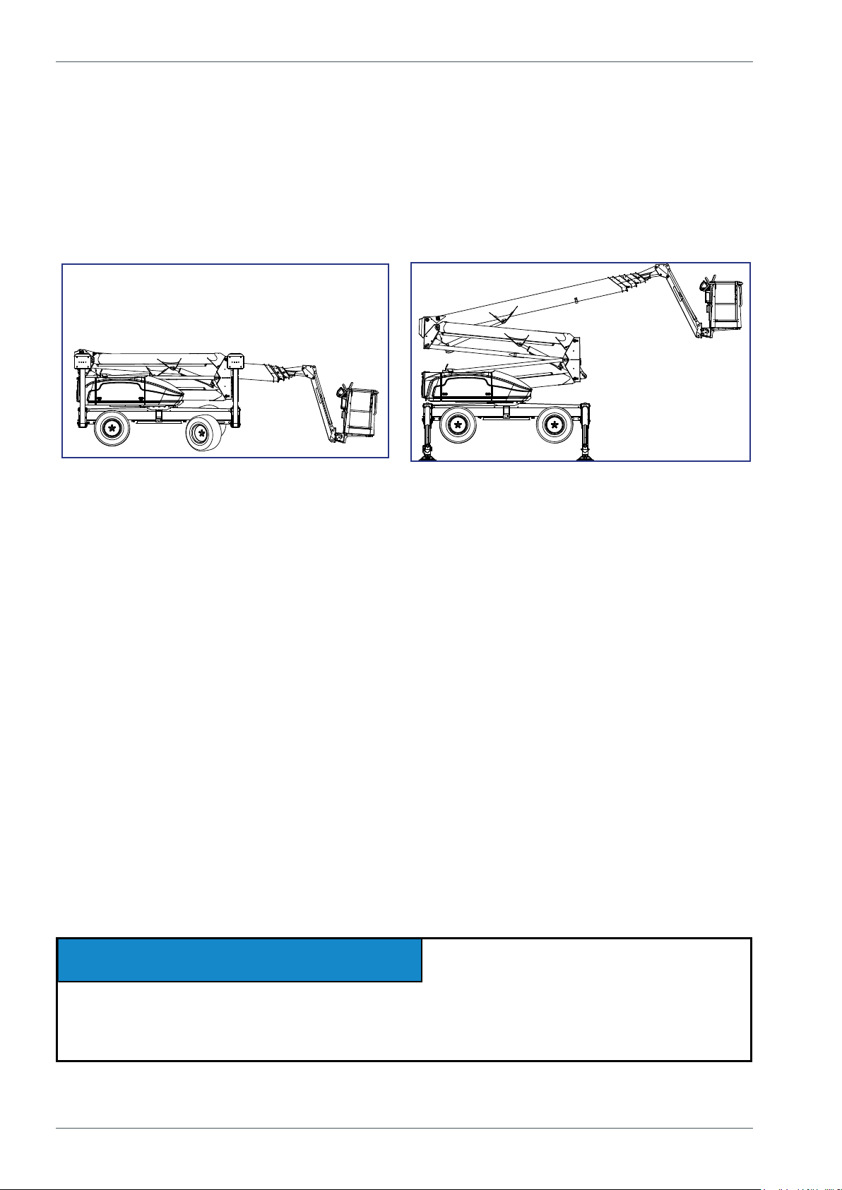
The unit is a wheeled, self-propelled aerial work platform. This aerial work platform complies
with the standard EN280 type 1, where driving is only allowed while the boom is in transport
position. The boom supported aerial work platform is operated from the control station on the
platform.
For lifting the unit is supported by its hydraulic stabilisers. They must be extended so that the
unit's wheels lift off the ground.
The lift's primary power source is a diesel engine. A mains-powered electric motor
is available as an auxiliary power source. The stabilisers and the boom system are
hydraulically powered.
Consult the chapters “Technical data" and “Structure and functions of the work platform" in
this manual for more detailed information about the lift.
1.2. INTENDED USE OF THE WORK PLATFORM
The aerial work platform is exclusively intended for transferring people and tools and acting
as a work platform within its permissible load-bearing capacity and reach (refer to the
“Technical Specications” table and the “Reach Diagram”).
The intended use also covers:
• Following all the instructions in the Operating Instructions
• Performance of the inspections and maintenance operations.
This aerial work platform is NOT insulated, and does not offer protection against contact with
electric current. The aerial work platform must not be used for work on electric systems.
Observe the safety instructions concerning the operating environment, and the restrictions
given in them,
DANGER
WARNING
CAUTION
NOTICE
The operator must receive instructions and consent from the manufacturer for all such
specic work methods or conditions that the manufacturer has not explicitly dened in the
unit's operation and maintenance instructions.

9
2. TECHNICAL SPECIFICATION
280RXT
Max. working height 28,0 m (91 ft 10")
Max. platform height 26,0 m (85 ft 4")
Max. outreach 16,0 m (52 ft 6")
Boom rotation continuous
Platform rotation 180°
Jib arms 1,6m (63") / 140°
Turn area refer to the reach diagram
Support width 3,8 m x 4,2 m (12 ft 6" x 13 ft 9")
Transport width 2,05 m (80")
Transport length 5,8 m (19 ft 1")
Transport height 2,4 m (7 ft 9")
Weight 4860 kg (10715 lbs)
Max. allowed load on platform 230 kg (507 lbs)
Max. number of persons + additional load 2 persons + 70 kg (154 lb)
Max. allowed sideways load (caused by persons) 400 N (100 lbf)
Max. lateral inclination (chassis) ±1°
Max. wind speed during operation 12,5 m/s (28 mph)
Min. ambient temperature when working - 20 °C (-4 °F)
Max. support force on the stabilisers 29 000 N (6520 lbf)
Platform size 0,7 x 1,3 m
(2ft 4" x 4ft 3")
Driving speed max. 10 km/h (4,2 mph)
Gradeability 40% (22°)
Power supply
- Combustion engine (Diesel) KUBOTA D1105
(EPA / CARB Tier 4 Final)
Net power 18,5 kW (24,8 hv) / 2800 r/min
Fuel tank volume 82 l (22 gal)
Oil volume 5,1 l (5,3 qt)
Coolant volume 3,1 l (3,3 qt)
Quaranteed sound power level Lwa 102 dB
Sound pressure level (UCB/LCB) 72 / 85 dB
Whole-body vibration
(driving/high speed) 1,0 m/s2
Whole-body vibration
(work, driving/low speed) < 0,5 m/s2
- Mains current (optional) 230/50Hz/16A
Sound pressure level < 70 dB
Whole-body vibration not detectable
Socket outlets on the platform 2 x 230V/50Hz/16A
12V
USB

10
Operating instructions • DINO 280RXT
2.1. DIMENSION DRAWINGS
7422
shortened transport position 5800
2300 9364156
2040
2390
1982
4580
4157
3750
4158
Rev.
Muutos
Pvm.
Muut
Hyv
DINO 280RXTII
PÄÄKOKOONPANO
4733.33
1:50
1155SW
Uusi
Ent.
Liittyy
Tuote
Mittakaava
Yleistoleranssit
Massa
Hyv.
Suunn.
Piirt.
DINO Lift
SFS-EN 22768-1

11
2.2. REACH DIAGRAM
120 kg
230 kg
120 kg
230 kg
12
Operating instructions • DINO 280RXT
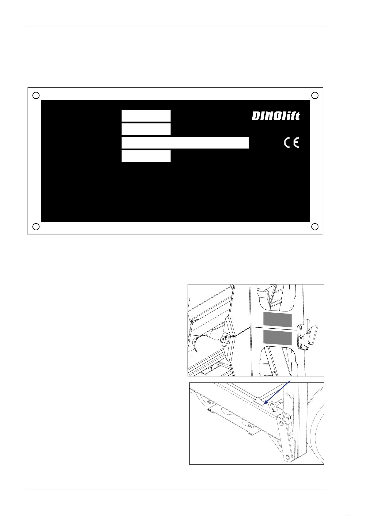
The nameplate and machine inspection plate
are located as shown in the picture.
The serial number is also engraved in the
chassis.
2.3. EXAMPLE OF MACHINE’S NAMEPLATE
Every machine has a nameplate shown in the picture below. In the nameplate are marked
the name and address of machine manufacturer, serial number of the machine and other
relevant machine information.
Raikkolantie 145
32210 Loimaa
FINLAND
400 N
230 V
-20 C
o
12,5 m/s
50 Hz
o
kg
kg
DINO
54.xxxx
Number of manufacture
Type Manufacturer
Year of manufacture Address of manufacture
Voltage Frequency
Min operating temp. Max wind force
Weight kg Max load 230
Max side force Max inclination of chassis 1
Max load of persons Additional load
2 70
MEWP
Description of the machine: MEWP = “Mobile Elevating Work Platform”.

13
2.4. MODEL OF EC-DECLARATION OF CONFORMITY
EC-Declaration of Conformity for Machinery
Manufacturer
Dinolift Oy
Raikkolantie 145
FI-32210 Loimaa, FINLAND
declares that
DINO 280RXT Access Platform no YGC280RXTK0080030
is in conformity with the provisions of Machinery Directive 2006/42/EC as amended and
with national implementing legislation.
2006/42/EC Conformity assessment procedure followed: Annex VIII: internal control of
production.
Access platform also fulls the requirements of the following EC directives:
2000/14/EC, 2014/30/EU
Measured sound power level Lwa ( 100 + 1,5 ) 101,5 dB
Quaranteed sound power level Lwa 101,5 + 0,5 dB
2000/14/EC Conformity assessment procedure followed: Annex V: Internal control of
production.
Following harmonized standards have been applied in designing the machine:
SFS-EN 280:2015; EN 13849-1:2015; SFS-EN 60204-1/A1; SFS-EN-ISO 12100:2010
Person authorized to draw up the Technical File: Santtu Siivola
Chief Engineer
Dinolift Oy, Raikkolantie 145,
32210 Loimaa, FINLAND
Loimaa 30.06.2017
-----------------------------------------
Santtu Siivola
Chief Engineer
NOTICE! Unauthorized changes or signicant repairs that affect strength, stability or
operation of the machine will cause the CE marking and EC declaration of conformity to
become unvalid.
14
Operating instructions • DINO 280RXT
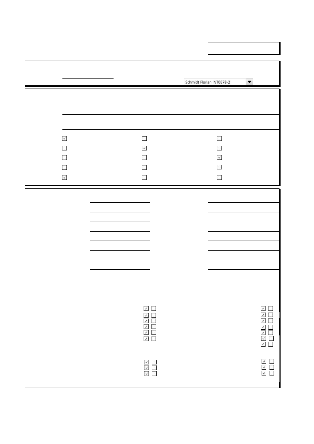
2.5. MODEL OF INSPECTION PROTOCOL FOR THE ACCESS PLATFORM
TEST CERTIFICATE
DATE: I
START-UP TESTS:
Inspection place: Dinolift Oy Inspector's signature: I
I
BASIC INFORMATION
Manufacturer: Dinolift OY Place of manufacture: Finland
Address: Raikkolantie 145
32210 LOIMA
A
Importer:
Type of lift:
Chassis:
Boom:
Outriggers:
TECHNICAL SPECIFICATIONS
Machine and type: DINO 280RXT Max. platform height 26,0 m
Number of manufacture IMax. outreach: Depend on load
Year of manufacture I
Max. lifting capacity: 230 kg Boom rotation: Continuous
Max. person number: 2Support width: 3,8 m
Max. additional load: 70kg Transport width: 2,08 m
Power supply: Diesel Transport length: 5,82 m
Lowest temperature: -20 °C Transport height: 2,37 m
Weight: 4860 kg Basket size: 0,7x1,3
INSPECTION POINTS: (Y = meet standards N = do not meet standards)
Y
N
Y
N
A. GENERAL REQUIREMENTS C. STRUCTURES
1. Suitability for use 1. Transport position / transp. equipment
2. Certificate of conformity 2. Driving/towing equipment
3. User manual and storage 3. Chassis
4. Machine plate - inspection plate 4. Turning device
5. Instructional and safety plates 5. Boom system
6. Safety colours 6. Structure and position of work platform
7. Hydraulic system
B. STABILITY D. ELECTRIC SYSTEM
1. Load plate and reach diagram 1. Electric system
2. Supports / outriggers 2. Electric appliances
3. Indicator for horizontal position 3. Lights
Boom platform Scissor platform Mast platform
Car Self propelled Trailer mounted
Articulated boom Telescopic boom Articulated telescopic boom
Fixed mast Telescopic mast Scissor
Hydraulic turning Hydraulic pushing Mechanical
15
Dino access platforms are subjected to an overload test and structural and functional
inspection for the rst time at the factory by the manufacturers authorized inspector. This is
a model of a test certicate that is drawn up based on the inspection and delivered with the
platform.
Keep this certicate and all other inspection documents with the platform stored in the place
reserved for them for a minimum of 5 years.
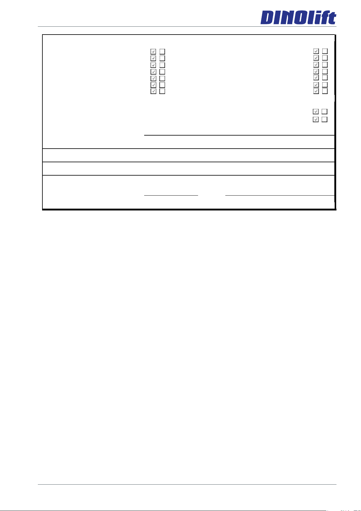
E. SAFETY AND CONTROL DEVICES F. SAFETY FEATURES
1. Safety limit switches 1. Prevention of unauthorized use
2. Sound signal 2. Locking device, covers and guards
3. Emergency descent system 3. Prevention of lifting
4. Protection of controls 4. Prevention of opening of support
5. Symbols / control directions 5. Safety distances
6. Placement of controls 8. Control of loading
7. Emergency stop 9. Limiting devices
G. TEST LOADING
1. Overload test (150%) 345 kg
2. Functional test (110%) 237 kg
FAILINGS AND NOTES
Failings have been repaired. Date: Signature:

16
Operating instructions • DINO 280RXT
3. SAFETY
All the essential safety instructions and warnings, relevant to transport, use and maintenance
of the lift, are described in this chapter.
DANGER
WARNING
CAUTION
NOTICE
Failure to observe these instructions and safety regulations may cause a severe injury or
even death. Familiarise yourself with all the safety regulations, operating instructions and
signs afxed to the machine, and follow them.
Make sure that you understand all the safety instructions and regulations. Also make sure
that others operating the machine or working on the work platform are familiar with these
instructions.
3.1. SAFETY INSTRUCTIONS
Only specially trained personnel with authorisation in writing, who are well familiarised with
the device, and at least 18-years old, are allowed to operate the unit.
Keep the lift free of any dirt, which may impair safe operation, and impede the inspection of
the structures.
The device must be serviced and inspected regularly.
Only skilled persons, familiar with the service and repair instructions, are allowed to carry out
servicing and repair work.
It is strictly prohibited to use a lift which is out of order.
Never remove or disable any safety devices of the machine.
DANGER
WARNING
CAUTION
NOTICE
The device must neither be altered without the manufacturer’s consent nor be used under
conditions, which do not meet the manufacturer's requirements.
The operator must receive instructions and consent from the manufacturer for all such
specic work methods or conditions that the manufacturer has not explicitly dened.

17
TRANSFERS
Observe the maximum allowed gradient when transferring the lift. During transfer in rough
terrain, always try to position yourself higher than the machine.
Beware of xed or moving obstacles in the terrain or near the lift while driving. Make sure
that you have a clear view of the driving path.
Do not use the machine for towing.
WORK AREA AND PREPARATIONS BEFORE LIFTING WORK
When working in busy areas, the operating range of the lift must be clearly marked by using
either warning lights or fencing.
Also observe the road trafc regulations.
Ensure the unobstructed range of movement before operating the outriggers.
The load-bearing capacity and the gradient of the base must be taken into account when
supporting the chassis. Do not use the lift if it is on a lorry, a railway car, a oating vessel or
any other potentionally unstable platform.
Ensure that the outriggers cannot slide while on a gradient.
Additional support plates of adequate size must be used under the outriggers, when working
on soft ground. Only use such additional support plates, on which the metallic outriggers will
not slide.
While in the support position, ensure that the wheels are off the ground.
Always ensure the level position of the machine before starting the operation.
Always ensure that the work area is clear of outsiders. Danger of getting squeezed between
rotating and xed structures.
While operating the boom from the control centre on the turning device, beware of
getting pressed against the outriggers or other structures that do not turn with the
boom.
18
Operating instructions • DINO 280RXT
LIFTING AND WORKING ON THE PLATFORM
Never exceed the maximum number of persons, maximal loading or hand power, allowed for
the lift. Never add load onto the platform while in the upper position.
Before operating, always ensure that the safety devices and the emergency descent system
are in working order.
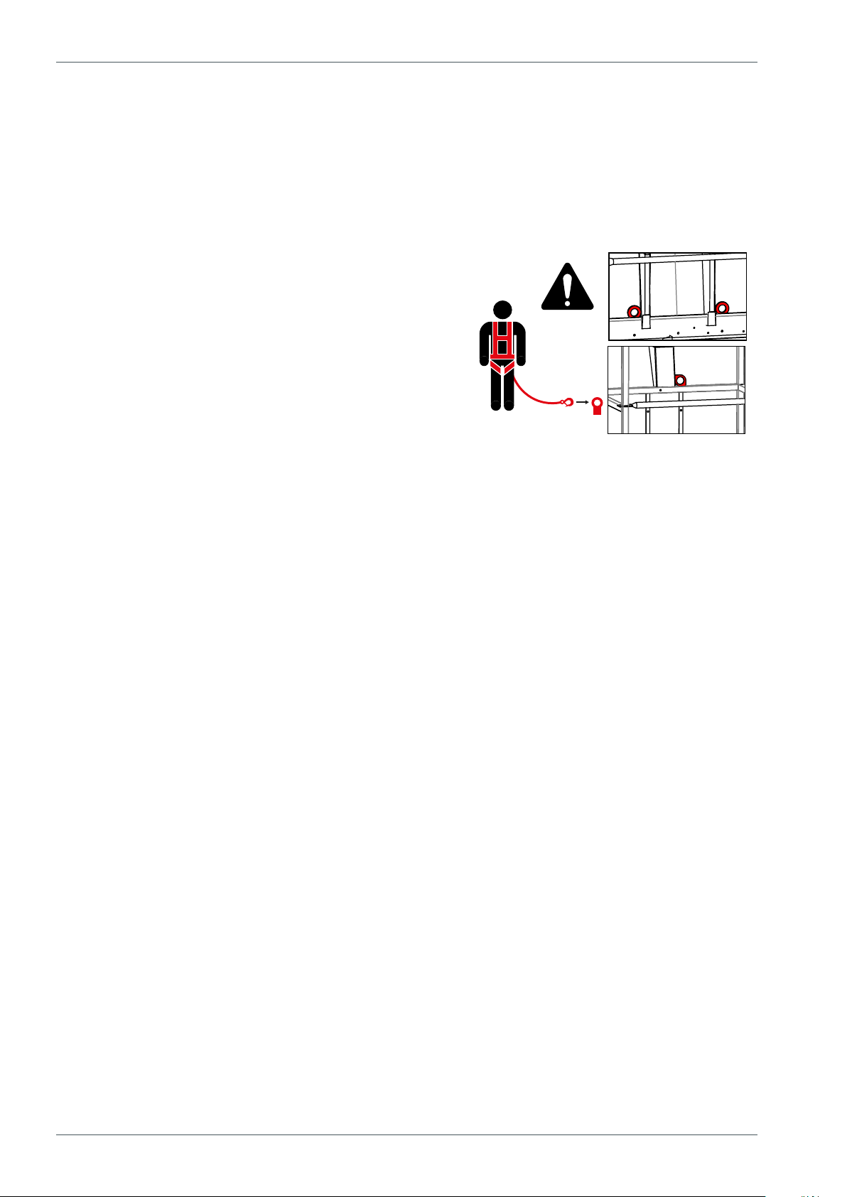
Use the safety harness! Fix the safety harness
to the xing points, intended for the purpose.
Note! The platform is tted with a xing point for the
safety harness of each user. Only one harness per
xing point.
Do not use ladders, steps or other similar equipment
on the platform.
Ensure that the gates are properly closed before starting the operation. If the work platform
is equipped with ladder, these must be locked in the upper position.
Never throw or drop any objects from the platform. All the tools must be transported on the
inside of the platform. Never leave the tools hanging outside the work platform, supported
only by their power cord.
Do not lift the tools, accessories or other material on the railing of the platform or attached to
the railing.
The aerial work platform must not be used for lifting.
The work platform must not be used for transferring goods or persons between different
oors or working levels. Stepping on or off the platform in motion is prohibited.
When the boom is in its lowest positions, make sure it cannot clash during rotation with
structures that do not turn with the boom.
Always make sure, before lowering the platform, that the area under it is clear.
Avoid damaging the platform by lowering it on the ground, or bringing it in contact with any
structures.
Never use a lift alone. Make sure that there is always someone on the ground, who can call
for help in case of an emergency.

19
OPERATING CONDITIONS
The weather conditions, such as wind, visibility and rain, must always be taken into account
so that these will not adversely affect the safe performance of the lifting operations.
The use of the lift is prohibited, if
the temperature drops under -20 °C or
the wind speed exceeds 12.5 m/s
Wind speed ( m/s) Conditions on land
0 Calm Smoke rises vertically
1-3 Light breeze Smoke moves with the wind and the wind feels on exposed
skin. Leaves rustle.
4-7 Gentle breeze
Leaves and small branches of trees are moving. Flag is
ying. Wind lifts dust and loose pieces of paper from the
ground.
8-13 Strong breeze
Small broad-leaved trees and large branches sway. Wind
whistles as it hits houses or other xed objects. Umbrella is
difcult to use.
14-17 Strong All the trees are swaying. It is difcult. to walk against the
wind.
NOTE! The wind speed can be much higher at a higher altitude than on the ground level.
Do not take tools/material of large surface area onto the platform. The increase in wind load
may jeopardize the stability of the device.
Beware of the live aerial power lines in the area – observe the minimum
safety distances:
Voltage range (phase to
phase)
Minimum distance
Metres Feet
0–300 V Avoid contact
300 V–50 kV 3 10
50 kV–200 kV 4.5 15
200 kV–350 kV 6 20
350 kV–500 kV 8 25
500 kV–750 kV 11 35
750 kV–1000 kV 14 45
These distances shall apply unless more stringent limits are given in worksite instructions or
in local or governmental regulations.
This aerial work platform is NOT insulated, and does not offer protection against contact with
electric current. The aerial work platform must not be used
for work on electric systems.
20
Operating instructions • DINO 280RXT
3.2. SAFETY-RELATED NOTIFICATIONS
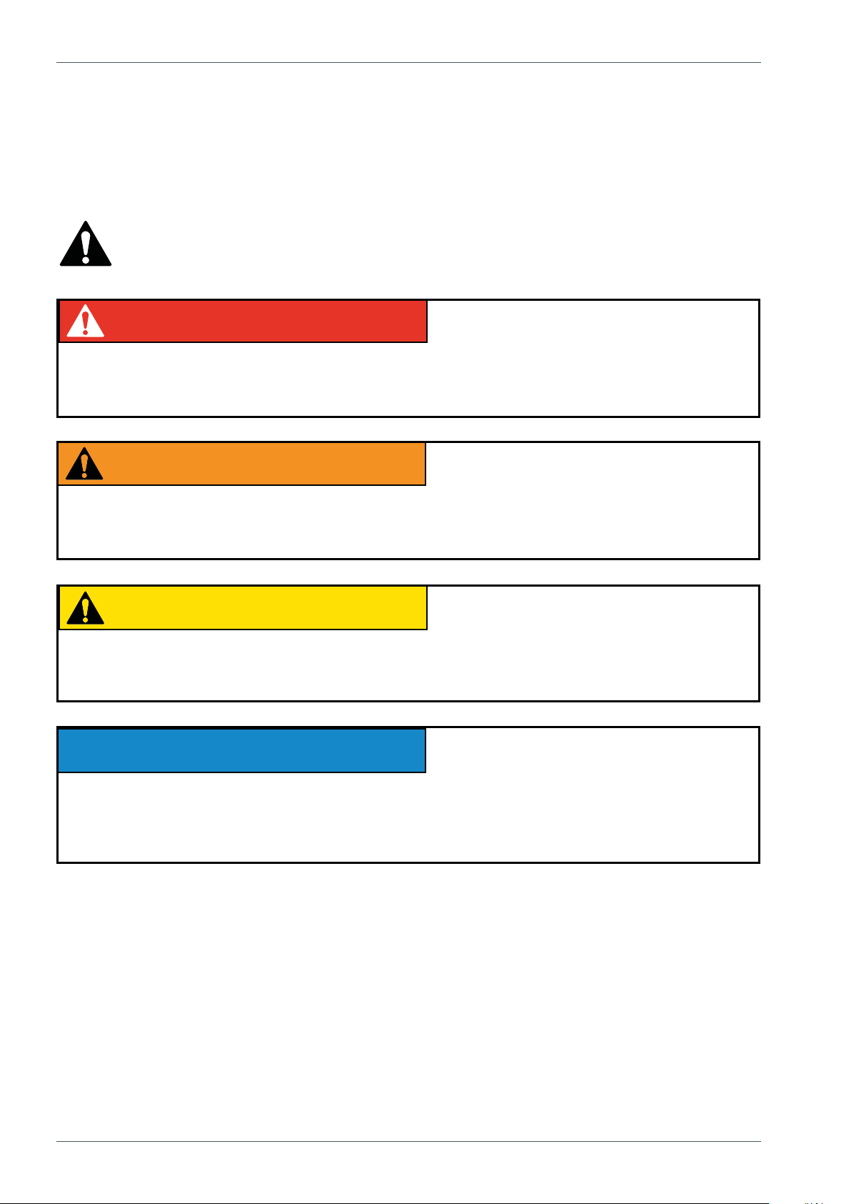
The following safety alert symbols and safety signal words are used in this manual.
Observe all the safety instructions that follow these symbols, in order to avoid dangerous
situations and personal injuries.
This is a general safety alert symbol and it is used to alert you about a potential
hazard. Observe the additional instructions given in form of text or symbols that
follow this symbol.
DANGER
WARNING
CAUTION
NOTICE
Red DANGER-message warns for an imminent or potential hazardous situation which, if
not avoided, may result in death or serious injury.
DANGER
WARNING
CAUTION
NOTICE
Orange WARNING -message is used in connection with potential risk factors, which if not
avoided, under certain conditions, may result in death or serious injury.
DANGER
WARNING
CAUTION
NOTICE
Yellow CAUTION -message is used to warn about a hazardous situation which, if not
avoided, could result in minor or moderate injury.
DANGER
WARNING
CAUTION
NOTICE
Blue notice-message is used to draw your attention to special notications or instructions
that are related to the operation or maintenance. Such messages include, for example,
instructions that are related to reliability of the machine or aim to avoid material losses.
Table of contents
Other Dino lift Boom Lift manuals

Dino lift
Dino lift 240RXT Technical specifications

Dino lift
Dino lift DINO 185XTC II User manual

Dino lift
Dino lift DINO 260XTD Technical specifications

Dino lift
Dino lift 135TB II User manual

Dino lift
Dino lift 240RXT User manual

Dino lift
Dino lift DINO 160XT II User manual

Dino lift
Dino lift DINO 185XTC II Instructions for use
Popular Boom Lift manuals by other brands


Haulotte
Haulotte SUMMIT Series Operator's manual

Manitou
Manitou MHT 10180 129 M ST4 S1 Operator's manual

Sinoboom
Sinoboom TB14J Plus Maintenance manual

Oshkosh Corporation
Oshkosh Corporation JLG H800AJ Service and maintenance manual

JLG
JLG G6-42A Supplemental repair manual

Terex
Terex Genie Z-34/22 IC Service and repair manual


