ATO MF5700 Series User manual

Gas Mass Flow Meter
VC.3
Model MF5700

MF5700UserManual
1
|
Page
Gas Mass Flow Meter
withMEMSthermalsensingtechnology
MF5700Series
User Manual
DocumentNo. 11‐2021‐MF2EN
Issuedate: 2021.11
Revision: VC.3

2
|
Page
Attention!
Usewithcaution!
Pleasecarefullyreadthismanualpriortooperatingthisproduct.
Donotopenormodifyanyhardwarewhichmayleadtoirrecoverable
damage.
Donotusethisproductifyoususpectanymalfunctionsordefection.
Donotusethisproductforcorrosivemediaorinastrongvibration
environment.
Usethisproductaccordingtothespecifiedparameters.
Onlythetrainedorqualifiedpersonnelshallbeallowedtoperform
productservices.
Becautiousfortheelectricalsafety,evenitoperatesatalowvoltage,
anyelectricalshockmightleadtosomeunexpecteddamages.
Thegastobemeasuredshouldbecleanandfreeofparticles.Donotapply
thismeterforliquidmedium.
Donotapplyforanyunknownornon‐specifiedgasesthatmay
damagetheproduct.
ForwirelessdatawithNB‐IoT,pleasebesurethenetworkisavailable.
MF5700UserManual

3
|
Page
TableofContents
1. Overview..................................................................................................5
2. Receipt/unpackoftheproducts................................................................6
3. Knowingtheproducts...............................................................................7
3.1Productdescription...............................................................................................7
3.2LCDdescription.....................................................................................................8
3.3Poweranddatacabledescription...........................................................................9
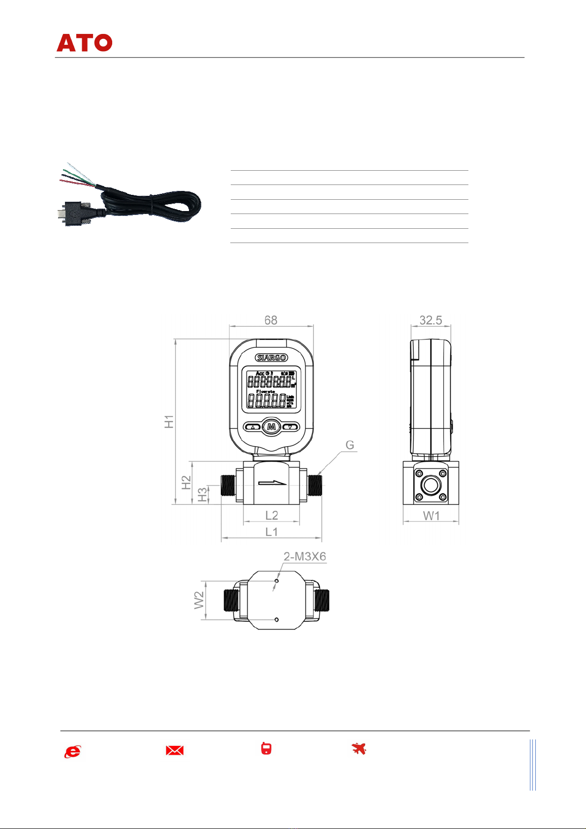
3.4Mechanicaldimensions..........................................................................................9
4. Installation..............................................................................................11
5. OperationandMENUdescription..............................................................14
5.1Checktheproductspecifications...........................................................................14
5.2Checktheleakage...............................................................................................14
5.3Powerthemeteranddigitaldataconnection.........................................................14
5.4Wirelessdatacommunication...............................................................................15
5.5MeterMENUdescription......................................................................................15
5.5.1Startingthemeasurement............................................................................................16
5.5.2MENUentrywithaverifiedpassword............................................................................16
5.5.3SettheRS485Modbusaddress......................................................................................17
5.5.4SettheRS485communicationbaudrate........................................................................17
5.5.5Resetorcalibratetheoffset..........................................................................................17
5.5.6Gasconversionfactor(GCF)fordifferentgasmeasurement.............................................18
5.5.7SettheResponsetime..................................................................................................18
5.5.8Selectthedisplaymode................................................................................................19
5.5.9Selectthedisplaylanguage...........................................................................................19
5.5.10Open/closethevalve.....................................................................................................19
5.5.11Setanalarm:upperinstantflowratelimit.....................................................................20
5.5.12Setanalarm:lowerinstantflowratelimit.....................................................................20
5.5.13Setanalarm:accumulatedflowrateortotalizerlimit.....................................................21
5.5.14Changethedefaultpassword........................................................................................21
MF5700UserManual

4
|
Page
5.5.15Resettheaccumulatedortotalizedflowrate..................................................................22
5.5.16ExittheMENU..............................................................................................................22
5.5.17Sleepingmode.............................................................................................................22
5.5.18Wakeupthemeter.......................................................................................................22
5.5.19MENUkeysequenceforthesettings..............................................................................23
5.6RS485Modbuscommunicationprotocol...............................................................24
5.6.1Hardwareconnection....................................................................................................24
5.6.2Communicationparameters..........................................................................................24
5.6.3Frame..........................................................................................................................25
5.6.4Functioncodes.............................................................................................................25
5.6.5Registers......................................................................................................................25
6. Productselectionandorderinformation...................................................29
6.1Productselection................................................................................................29
6.2Ordercontactandcustomersupport.....................................................................29
7. Technicalspecifications............................................................................30
8. Technicalnotesfortheproductperformance.............................................31
8.1Measurementprinciple........................................................................................31
8.2Precautionsforthebestperformanceoftheproduct..............................................31
8.2.1Comparisonwithathirdpartyreferencemeter...............................................................31
8.2.2Particlecontaminationandfluidiccleanness..................................................................32
8.2.3Applytoadifferentgasmedium....................................................................................32
9. Troubleshooting......................................................................................33
10. WarrantyandLiability..............................................................................34
11. Servicecontact........................................................................................36
AppendixI:Productevaluationkit..................................................................37
AppendixII:Documenthistory.......................................................................38
MF5700UserManual

5
|
Page
1. Overview
Allcontactinformationcanbefoundattheendofthismanual.
ThismanualprovidesessentialinformationfortheoperationoftheMF5700seriesofgasmassflow
metersgeneral‐purposegasmetrologyapplications.Theproductperformance,maintenance,and
trouble‐shootingaswellastheinformationforproductorder,technicalsupport,andrepairarealso
included.
TheMF5700massflowmeterisoneofthebest‐sellingmassflowmeterproductsonmarket,dueto
itsperformanceandcost‐effectivedesignenabledwiththecompany’sproprietaryMEMS(micro‐
electro‐mechanicalsystems)thermalsensingtechnology.Thecurrentmodelisthe3rdgenerationof
the products having significantly upgraded features since its first release in 2010. The upgrade
includes much‐improved accuracy, an additional model to cover flow range and channel size
compatibility;significantlyextendedmeasurementdynamicrange,wirelessdataoptions,andvalve
options. The upgrade also ensures back‐compatibility for our existing customers. ATO is
committedtocontinuingproductinnovationwhileofferingthebestvaluetoourcustomers.
Thisserialofproductsisdesignedforgeneralpurposemassflowsensingandcontrolpurposes.The
wettedmaterialsoftheproductsarecompatiblewithmostofthecommongasessuchasoxygen,
nitrogen, air, argon, carbon dioxide, etc.ATO also offers a wide spectrum of off‐the‐shelf and
customized flow, pressure, temperature/humidity, and gas concentration sensing products and
providesintegrationandturn‐keysolutionstoourcustomers.Pleasecontactthemanufacturerfor
additionalinformation.
MF5700UserManual

6
|
Page
2. Receipt/unpackoftheproducts
Uponreceiptoftheproducts,pleasecheckthepackingboxbeforethedismantlementofthepacking
materials.Ensurenodamagesduringshipping.Ifanyabnormalityisobserved,pleasecontactand
notifythecarrierwhoshippedtheproductandinformthedistributorsorsalesrepresentativesifthe
orderisnotplaceddirectlywiththemanufacturer,otherwise,themanufacturershouldbeinformed
aswell.Foranyfurtheractions,pleaserefertothereturnandrepairsectioninthismanual.
Ifthepackingboxisintact,proceedtoopenthepackingbox,andyoushallfindtheproduct(either
themeterorthemeterwiththevalvepertheactualorder).Thepoweradapterand/ordatacableas
shownbelowmayalsobefoundaccordingtoyouractualorder.
or
Flowmeter Flowsensor+valve Adapter datacable
Figure2.1:MF5700flowmeterandaccessories
Pleasecheckimmediatelyfortheintegrityoftheproductaswellasthepoweranddatacable,ifany
abnormalisidentified,pleasenotifythedistributor/salesrepresentativeormanufacturerassoonas
youcan.Ifanydefectsareconfirmed,anexchangeshallbearrangedimmediatelyviatheoriginal
saleschannel.(Note:theLCDscreenshallnotbelighteduntilthebatteryisinstalledorthepower
cableispluggedin).Thisusermanualshallalsoeitherbeincludedinthepackingboxorviaanonline
requestforanelectronicversion.Inmostcases,thismanualshallbemadeavailabletothecustomer
beforetheactualorder.
Themeterisdesignedwithlowpowerthatcanbeoperatedwith4AAbatteries.However,ifyou
orderedtheproductwiththecontrolvalve,itisrecommendedtohaveexternalpowersincethevalve
requireslargepowerconsumption.Apoweradaptermusthaveasafetycertificationforusewiththis
meter.Theexternalpower/dataconnectorisatype‐CUSB.Seethedetailedrequirementsinthe
operationsection.
MF5700UserManual

7
|
Page
3. Knowingtheproducts
3.1 Productdescription
Figure3.1:MF5700partsdescription
Figure3.2:MF5700withvalve
Meterhead
(rotatable)
Meterbody
LCDdisplay
MENUkeys
BSPP
connector
Flow
direction
Battery
chamber
cover
Dataand
powerport
Installation
screws
ON/OFF
solenoidvalve
MF5700UserManual

8
|
Page
3.2 LCDdescription
TheLCDprovidesallinformationthattheproduct
measures.Somesymbolsarereservedforfuture
upgrades,andwillnotbelightedduringthe
operation.Thefollowingtabledetailsthemeaning
ofeachofthesymbols.
Figure3.3:LCDsymbolillustration.
Table3.1:Symbolsdescription
ACC
Thetoprow.ThedefaultdisplaysthetotalizedflowrateinL(liters),
m3(cubicmeters),orSCF(standardcubicfeet).Italsodisplays
pressure(ifkPalightsup)ortemperature(if°Clightsup)*.
FlowThe2nd
row.DisplaysinstantflowrateinL/min(Litersperminute)or
SCFH(standardcubicfeetperhour)orm3/h(cubicmetersperhour).
Batterystatus.
Valvestatus.ThecurrentproductprovidesanON/OFFcontrolvalve.
LoRawirelessprotocolisenabledwhenlightsup.
NB‐IoTwirelessprotocolisenabledwhenlightsup.
WIFIwirelessprotocolisenabledwhenlightsup.
BluetoothLE4.2wirelessprotocolisenabledwhenlightsup.
ReservedforfutureupgradeofGPRSinclusion.
*Note:Boththepressureandtemperaturesensorscanbeintegratedwiththecurrentproduct
butnotwiththedefaultmodels.Pleasecontactthemanufacturerforfurther
information.
MF5700UserManual

9
|
Page
3.3 Poweranddatacabledescription
Table3.2:MF5700wireassignment.
Figure3.4:MF5700cable(USB‐C‐100)
3.4 Mechanicaldimensions
Figure3.5:MF5700meterdimensions
Wire Color Definition
1RedPowersupply(5~24Vdc)
2BlackGND,ground
3Green
RS485A
4
White
RS485B
MF5700UserManual

10
|
Page
Figure3.6:MF5700meterwithcontrolvalvesdimensions
Table3.3:Mechanicaldimensionsofthemeters/meterswithcontrolvalves
Connector,G
L1L2LV1LV2W1W2H1H2H3
MF5706BSPP¼”613495.512334251272812.5
MF5708BSPP3/8”814511013445301343515.5
MF5712BSPP½”905011514345301414219.5
MF5700UserManual

11
|
Page
4. Installation
Donotopenoralteranypartoftheproductwhichwouldleadtomalfunctionandirrecoverable
damage.Itwillalsoforfeitthetermsofthewarrantyandcauseliability.
Theproductatthetimeofshipmentisfullyinspectedforitsqualityandmeetsallsafetyrequirements.
Additionalsafetymeasuresduringtheinstallationshouldbeapplied.Thisincludes,butisnotlimited
totheleakageverificationprocedures,standardEDS(electrostaticdischarge)precautions,DC
voltageprecautions.Othertaskssuchascalibration,partreplacement,repair,andmaintenance
mustonlybeperformedbytrainedpersonnel.Uponrequest,themanufacturerwillprovide
necessarytechnicalsupportand/ortrainingofthepersonnel.
Theproductispreferabletobeinstalledhorizontally.Flowdirectionshouldbealignedwiththearrow
markonthemeterbody.Iftheflowingfluidmayhaveparticlesordebris,afilterisstrongly
recommendedtobeinstalledupstreamofthemeter.
Pleasefollowthefollowingstepstocompletetheinstallation:
Figure4.1:MF5700meterinstallation
a)Uponopeningthepackage,theproduct'sphysicalintegrityshouldbeinspectedtoensurenovisual
damage.
b) Beforeinstallationoftheproduct,pleaseensurethatthepipedebrisorparticlesoranyother
foreignmaterialsarecompletedremoved.
c) Cautionsduringinstallation:
(i)Itispreferablytofirstinstalltheinletendofthemeterandthentheoutletendofthemeter;
Toensurethemeasurementaccuracy,anupstreamstraightpipeoflengthnolessthan10DN
andadownstreamstraightpipeoflengthnolessthan5DNshouldbeinplace.Pleasereferto
thefollowingrecommendedinstallationconfiguration.
MF5700UserManual

12
|
Page
(a)90‐degreeelboworT‐piece (b)2x90‐degreeelbow
Figure4.2:MF5700meterinstallation
(ii)Iftheupstreamordownstreampipesizeisdifferentfromthatoftheproduct,thesizeofthe
installationlinepipediameter(s)shouldbelargerthantheflowchannel(pipe)sizeofthemeters
tobeinstalled.Forsometypicalsituations,pleasefollowtheinstallationrecommendation
detailedinthefollowingsketches.
(c)2x90‐degreeelbow,3D (d)Pipesize‐reduction
(e)Pipesizeexpansion (f)Controlvalveatupstreamordownstream
Figure4.3:MF5700meterinstallation
(iii)Duringinstallation,pleasemakesurenoforeignmaterials(suchaswater,oil,dirt,particles,
etc.)enterintotheinstallationpipeline.
MF5700UserManual

13
|
Page
d) Install4‐AAbatteriesintothebatterychamber.Incasethattheexternalpowersupplyisdesired,
connectelectricalwiresperthewiredefinitioninTable3.2.Pleasebesureofthepowersupply
range(i.e.,5~24VDC)andpowersupplypolarization.Ifanadapterotherthantheonesupplied
bythemanufacturer,makesuretheadaptermeetsindustrialstandardsandhasallsafety
certifications.
e) Forthecommunicationwireconnection,pleasefollowthedescriptioninTable3.2andmakesure
thatthewiresarecorrectlyconnectedtotheproperportsonyourdatadevice/equipment.Please
makesurethedatacablemeetsindustrialstandardswithpropershielding.
f) Oncethebatteryisinstalled,ortheexternalpowerissuccessfullyconnected,theLCDshouldbe
lightedupwiththeproperinformationdisplayedworkscorrectly.
g) Slowlyopenthevalve(s)ifany,upstreamordownstreamorbothofthepipeline,andthemeter
shouldthenstarttomeasuretheflowinthepipeline.
Note:becausethemeterhasalargedynamicalmeasurementrange,itcouldbenormalifyousee
thesmallinstantflowratebeforeyouopenthevalveastherecouldbesomeleakage.
However,makesurethemeterreadsnullwhenthereisnoflowpresentinthepipeline.
h) Thiswillconcludetheinstallation.
Cautions
a) Don'talteranypartsoftheproduct.
b) Ensuretheelectricalconnectionisproperlydonepertheinstructions.
c) Makesurenomechanicalstressesintheconnections.
d) Thestrongelectromagneticinterferencesourcesclosebyoranymechanicalshocksatthe
pipelinemayalsocreatemalfunctioningoftheproduct.
e) Slowlyopen/closevalvestopreventabruptpulseflowimpact.
MF5700UserManual

14
|
Page
5. OperationandMENUdescription
5.1 Checktheproductspecifications
Beforestartingtousethisproduct,checktheproductspecificationsthatcanbefoundinthismanual
orthebasicinformationlocatedonthebackpaneloftheproduct.
ThedetailedproducttechnicalspecificationscanbefoundinSection7.Foraspecificapplication,
thepressureratingmustnotbehigherthanthesystempressuretobemeasured,andtheflowrange
shouldalsobewithinthespecifiedones.Inmostcases,theuseofahighfull‐scalerangedmeterfor
theverylowflowratemeasurementoftenresultsinerroneousdata.Thegastobemeasuredmust
alsobeconsistentwiththatspecifiedbytheproduct.Beparticularlycautiousaboutthesupplied
voltageindicatedinthespecification.Ahighervoltagemayleadtoirrecoverabledamage,anda
lowervoltagewillnotpowertheproductforanydesiredfunctions.
Forthebestperformanceoftheproduct,itisadvisedthatthegastobemeasuredmustbecleanand
freeofparticlesorotherforeignmaterials.
5.2 Checktheleakage
Checkgasleakagebeforeanymeasurement.Ifitisneeded,thepressurizednitrogenoraircanbe
usedfortheleakagecheck.
5.3 Powerthemeteranddigitaldataconnection
AlthoughthisproductcomplieswiththeCE‐requiredEMCregulations,italsorequirestheproductto
beusedaccordingtothestandardelectricaldevicepractice.Forgeneral‐purposeusage,themeter
canbepoweredby4AAbatteries.Besuretoselectthebatterieswithsafetyproofandwithinthe
expirationdate.Donotusebatterieswithoutaknownmanufacturerandexpirationdate.Formodels
withcontrolvalvesorforextensiveusage,itisrecommendedtohavethemeterpoweredwith
externalDCpoweroranAC‐DCadapter.Makesurethesupplyvoltageiswithintherangeofthe
specifiedonesinSection7.Beforeconnectingtheproductwiththeexternalpower,makesurethe
standardelectricaldeviceprecautionssuchasEDS(electrostaticdischarge)andDCvoltageare
observed.Excessiveelectrostaticdischargemaydamagetheproduct.
MF5700UserManual

15
|
Page
ThepoweranddataareconnectedviaastandardType‐CUSBport.Themanufacturer‐supplied
Type‐CUSBcablehasthescrewlockingfixture.Itisrecommendedsuchafeaturetoensurethecable
isproperlyengagedandwillnotbeaccidentallygotunplugged.
Half‐duplexRS485Modbusisusedfordigitaldatacommunication.Makesurethewiresareproperly
connectedtothereceiverside.
5.4 Wirelessdatacommunication
Theproducthasoptionalwirelessdatatransmission,includingBluetoothLE4.2,LoRa,WIFI,andNB‐
IoTwirelessdata.
AnapplicationAPPnamed“ATOSmartMeter2.0”canbedownloadedfromeitherAppleStorefor
smartdevicesbasedontheiOSsystemorfromGooglePlayStoreforsmartdevicesbasedonthe
Androidsystem.
TheAPPprovidesthebasicfunctionstoaccessthemeter/sensordata,plotaninstantflowratechart,
calculatetotalizedoraccumulatedflowvolumeataspecifictimedefinedbytheuser.Itallowsthe
usertosendthelocaldatainstantlytoaremotedestinationwhenthewiredconnectionisnotan
option.Also,theinterfaceprovidesthereadoutoftheproductinformationaswellastechnical
supportinformation.
ForthedetailedprotocolsofLoRa,WIFI,andNB‐IoT,pleasecontactthemanufacturerforfurther
information.
5.5 MeterMENUdescription
Themeterhasafront3‐keyboardfortheusertosetthedesiredfunctions,accessdata,andcheck
forthestatus.TheMenukey(M)isatthecentralpositionthatallowstheusertoselectafunction
andconfirmationorotherrelatedactionsthatwillbedetailedbelow.Twokeys(“Up”and“Down”)
toselectthemenuandsub‐menu.
U
p
MENUDown
MF5700UserManual

16
|
Page
5.5.1 Startingthemeasurement
Oncethepowerissuppliedandnoabnormalissuesareobserved,
themeterisreadytoperformthemeasurements.Thedefault
displayisforthemassflowmeasurementhavingtwonumerical
linesontheLCD.Theupperlineistheaccumulatedortotalized
flowrate,andthelowerlineistheinstantflowrate.Ifthebattery
symbolturnsinto,proceedtochangethebatteryorplugin
theexternalpowercord.
5.5.2 MENUentrywithaverifiedpassword
Attheflowmeasurement(main)display,pressthecentral“M”MENUkey,itwillenterintothe
passwordsettingandverificationMENU.Thedefaultpasswordis“11111”.Ifthepasswordisincorrect,
thedisplaywillreturntothemaindisplay.
Toenteranewpassword,pressthe“Up”or“Down”keytochangethedigitthatflashes,andpress
the“M”keytoconfirm.Repeatthisprocessforall5digitsandthemeterwillenterintothemenu
settinginterfaces/screen.
Subsequently,theMENUallowstheuserto:
SetModbusaddress F2‐Addr
Changecommunicationbaudrate F3‐bPS
Resetorcalibratetheoffset F11‐oFFST
Enterthegasconversionfactor(GCF) F12‐GCF
Changetheresponsetime F16‐rESPS
Changethedisplaymode F38‐dISP
Changethedisplaylanguage F39‐LAnG
Open/Closethevalve F43‐VALVE
Setupperflowratelimitalarm F51‐ALM‐H
Setlowerflowratelimitalarm F52‐ALM‐L
Settotalizedoraccumulatedflowratealarm F53‐ALM‐A
Changethedefaultpassword F91‐PASS
Clearorresetthetotalizeroraccumulatedflowrate F92‐CLr‐A
ExitfromtheMENU F99‐qUIT
Note:Duringthisprocess,themeterwillcontinuetomeasuretheflowwithoutbeinginterrupted.
MF5700UserManual

17
|
Page
5.5.3 SettheRS485Modbusaddress
AfterthepasswordisverifiedandenteredintotheMENUsettings,
pressthe“Up”or“Down”keyuntilthescreenshowstheF2‐Addras
indicatedtotheleft.
TheModbusaddresshas3digits,whichcanbeanynumberbetween
001to255.Pressthe“M”keytoenterintothechangeaddressscreen.
Pressthe“Up”or“Down”keytochangetheflashingdigits,andthen
pressthe“M”keytoconfirm.Aftertheaddressisset,thedisplaywill
returntoF2‐Addr,whichindicatesthetaskiscompleted.Pressthe
“Up”or“Down”keytoselectF99‐qUITandthe“M”keytoexitthe
MENUandreturntotheMainDisplayscreen.
5.5.4 SettheRS485communicationbaudrate
Followingtheabove‐mentionedsteps,attheMENUsettingscreen,
usethe“Up”or“Down”keytoselectF3‐bPSandthenpressthe
“M”keytosettheRS485communicationbaudrate.
Thereare6baudratesselectable,dependingonyoursystem
requirements:4800,9600,19200,38400,57600,and115200.The
defaultbaudrateis9600.Usethe“Up”or“Down”keytoselectthe
desiredoneandpressthe“M”keytoconfirm.Thedisplaywillthen
returntotheF3‐bPSscreen,whichindicatesthetaskiscompleted.
Usethe“Up”or“Down”keytoselectF99‐qUITandthe“M”keytoexittheMENUandreturntothe
MainDisplayscreen.
5.5.5 Resetorcalibratetheoffset
Afteracertaintimeofusage,themeter’soffset(zeroflowrate)
mightormightnothaveasmallshift.Orwhenyouapplythemeter
fordifferentgases,theoffsetmightbeshifted.Toensure
measurementaccuracy,itisnecessarytoresetorcalibratetheoffset.
Followingtheabove‐mentionedsteps,attheMENUsettingscreen,
usethe“Up”or“Down”keytoselectF11‐oFFST.Beforeperforming
thetask,makesurethereisabsolutelynoflowintheflowchannel,
otherwise,itwillcreateevenbiggererroneousmeasurementresults.
MF5700UserManual

18
|
Page
Pressthe“M”keytoconfirmthetask,anditwillopenthesub‐MENUaskingyoutoconfirm.Usethe
“Up”or“Down”keytoselectthedesiredoneandpressthe“M”keytoconfirm.Thedisplaywillthen
returntotheF11‐oFFSTscreen,whichindicatesthetaskiscompleted.Usethe“Up”or“Down”key
toselectF99‐qUITandthe“M”keytoexittheMENUandreturntotheMainDisplayscreen.
5.5.6 Gasconversionfactor(GCF)fordifferentgasmeasurement
Forthegeneralpurposeoftheapplication,agasconversionfactor
(GCF)canbeappliedtometerthegasdifferentfromthedefaultone
ortheoneusedforcalibration.TheGCFisdeterminedbythe
thermalcalorimetricsensingprincipleaswellasthemeterfluidic
dynamicdesignandthecontrolcircuitry.Contactthemanufacturer
toobtainthevaluescorrespondingtothecorrectmodels.
TheGCFforairis1000.
Note:Ifthemeterduringpurchaseisorderedforaspecialrealgascalibration,contactthe
manufacturerbeforefurtherproceeding.
Followingtheabove‐mentionedsteps,attheMENUsettingscreen,usethe“Up”or“Down”keyto
selectF12‐GCF.Pressthe“M”keytoconfirm,anditwillopenthesub‐MENUshowingthecurrent
gasconversionvalue.Usethe“Up”or“Down”andthe“M”confirmingkeytoinputthedesiredvalue,
andpressthe“M”keyagaintocompletethetask.ThedisplaywillthenreturntotheF12‐GCFscreen,
whichindicatesthetaskiscompleted.Usethe“Up”or“Down”keytoselectF99‐qUITandthe“M”
keytoexittheMENUandreturntotheMainDisplayscreen.
5.5.7 SettheResponsetime
Followingtheabove‐mentionedsteps,attheMENUsettingscreen,
usethe“Up”or“Down”keytoselectF16‐rESPSandthenpress
the“M”keytosettheresponsetime.
Thereare6responsetimeselectable:125,250,500,1000,2000,and
5000,unitismsec.Thedefaultresponsetimeis125msec.Usethe
“Up”or“Down”keytoselectthedesiredoneandpressthe“M”key
toconfirm.ThedisplaywillthenreturntotheF16‐rESPSscreen,
whichindicatesthetaskiscompleted.Usethe“Up”or“Down”key
toselectF99‐qUITandthe“M”keytoexittheMENUandreturntotheMainDisplayscreen.
MF5700UserManual

19
|
Page
5.5.8 Selectthedisplaymode
Thisfunctionistosetthedisplaymodes,cycledisplaymode,or
fixeddisplaymode.Ifonelikestoswitchbetweenthesetwodisplay
modes,followingtheabove‐mentionedsteps,attheMENUsetting
screen,usethe“Up”or“Down”keytoselectF38‐dISP.Pressthe
“M”keytoconfirm,anditwillopenthesub‐MENUshowingthe
currentdisplaymode.Usethe“Up”or“Down”andthe“M”
confirmingkeytoselectthedesiredone,andpressthe“M”key
againtocompletethetask.ThedisplaywillthenreturntotheF38‐
dISPscreen,whichindicatesthetaskiscompleted.Usethe“Up”or“Down”keytoselectF99‐qUIT
andthe“M”keytoexittheMENUandreturntotheMainDisplayscreen.
5.5.9 Selectthedisplaylanguage
Thisfunctionisreservedforfutureupgrades.Thecurrentmodelsare
configuredtobeEnglishorChinesebasedontheshipping
geographicregions.However,ifonelikestoswitchbetweenthese
twodefaultlanguages,followingtheabove‐mentionedsteps,atthe
MENUsettingscreen,usethe“Up”or“Down”keytoselectF39‐
LAnG.Pressthe“M”keytoconfirm,anditwillopenthesub‐MENU
showingthecurrentlanguage.Usethe“Up”or“Down”andthe“M”
confirmingkeytoselectthedesiredone,andpressthe“M”key
againtocompletethetask.ThedisplaywillthenreturntotheF39‐
LAnGscreen,whichindicatesthetaskiscompleted.Usethe“Up”or“Down”keytoselectF99‐qUIT
andthe“M”keytoexittheMENUandreturntotheMainDisplayscreen.
5.5.10 Open/closethevalve
Thisfunctionistoopenorclosethevalve.Ifonelikestoopenorclose
thevalve,followingtheabove‐mentionedsteps,attheMENU
settingscreen,usethe“Up”or“Down”keytoselectF43‐VALVE.
Pressthe“M”keytoconfirm,anditwillopenthesub‐MENUshowing
thecurrentvalvestatus.Usethe“Up”or“Down”andthe“M”
confirmingkeytoselectthedesiredone,andpressthe“M”keyagain
tocompletethetask.ThedisplaywillthenreturntotheF43‐VALVE
screen,whichindicatesthetaskiscompleted.Usethe“Up”or
“Down”keytoselectF99‐qUITandthe“M”keytoexittheMENU
andreturntotheMainDisplayscreen.
MF5700UserManual
This manual suits for next models
3
Table of contents
Other ATO Measuring Instrument manuals