ATO ATO-PLR-CH48 User manual

Paperless Recorder
PAPERLESS RECORDER
USER MANUAL
SKU: ATO-PLR-CH48
Automation www.ato.com [email protected] Global Shipping +1 800-585-1519 (Toll-free)

I.Overview……………………………………………………………………………………………………….……
II. Main Technical Parameters.....................................................................................................................................1
III. Notes for Use and Installment...............................................................................................................................2
3.1 Notes for Use.......................................................................................................................................................2
3.1.1 Notes for Use of this Instrument................................................................................................................2
3.1.2 Notes for Use of the External Storage Media.............................................................................................2
3.2 Instrument Installment.........................................................................................................................................2
3.2.1 Installment Site...........................................................................................................................................2
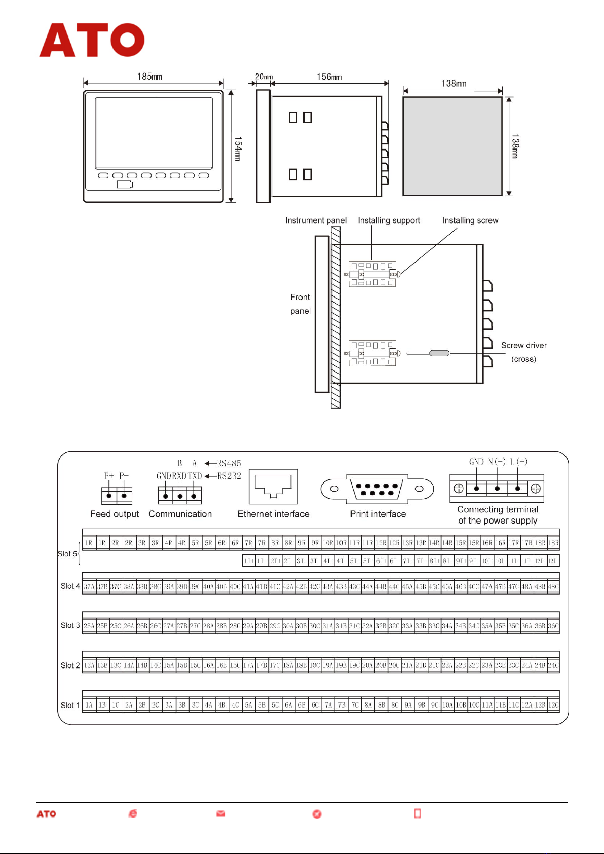
3.2.2 Installment Method.....................................................................................................................................3
IV. Instrument Function and Operation.......................................................................................................................5
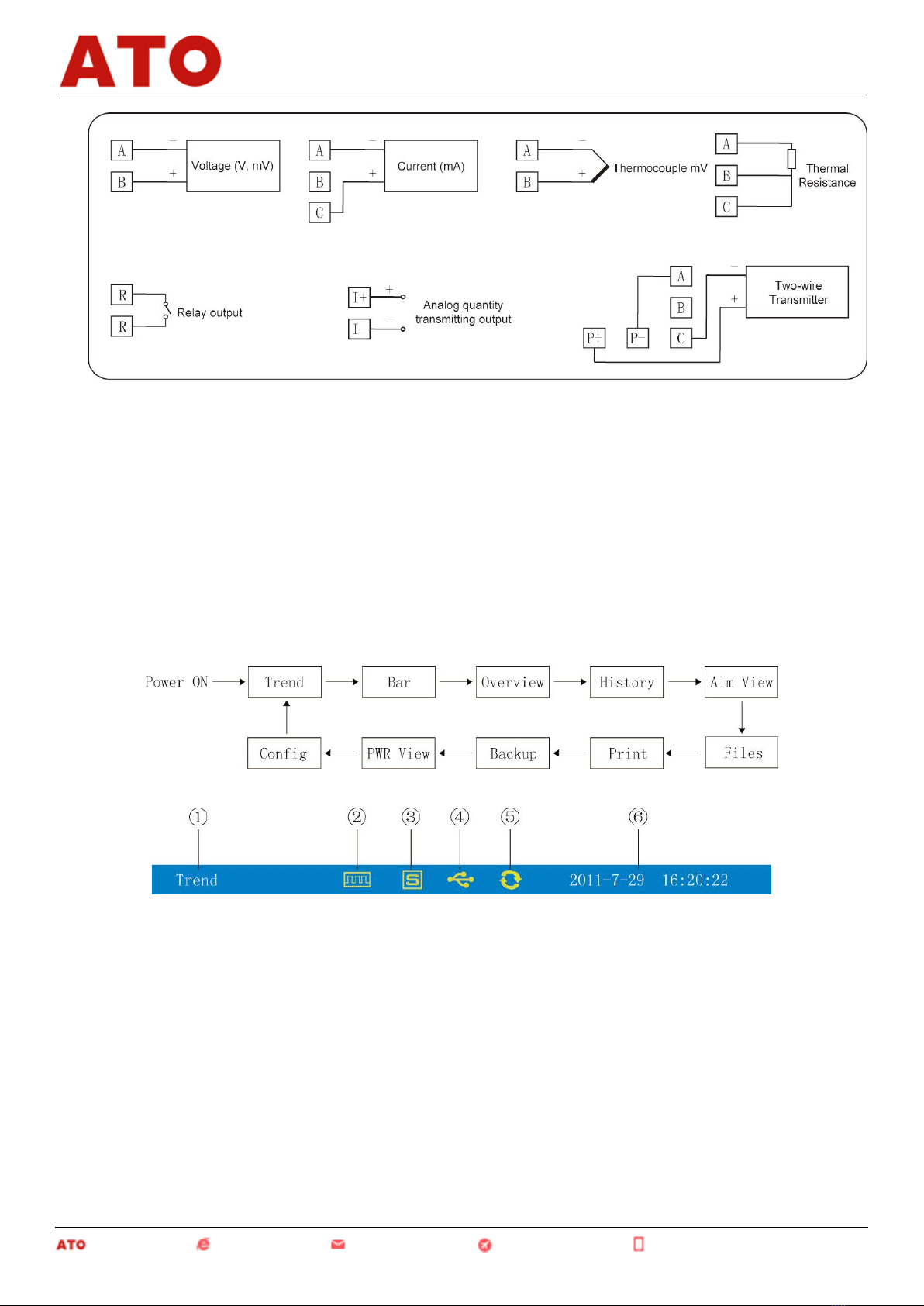
4.1 Switching of Operating........................................................................................................................................5
4.2 Status Display......................................................................................................................................................5
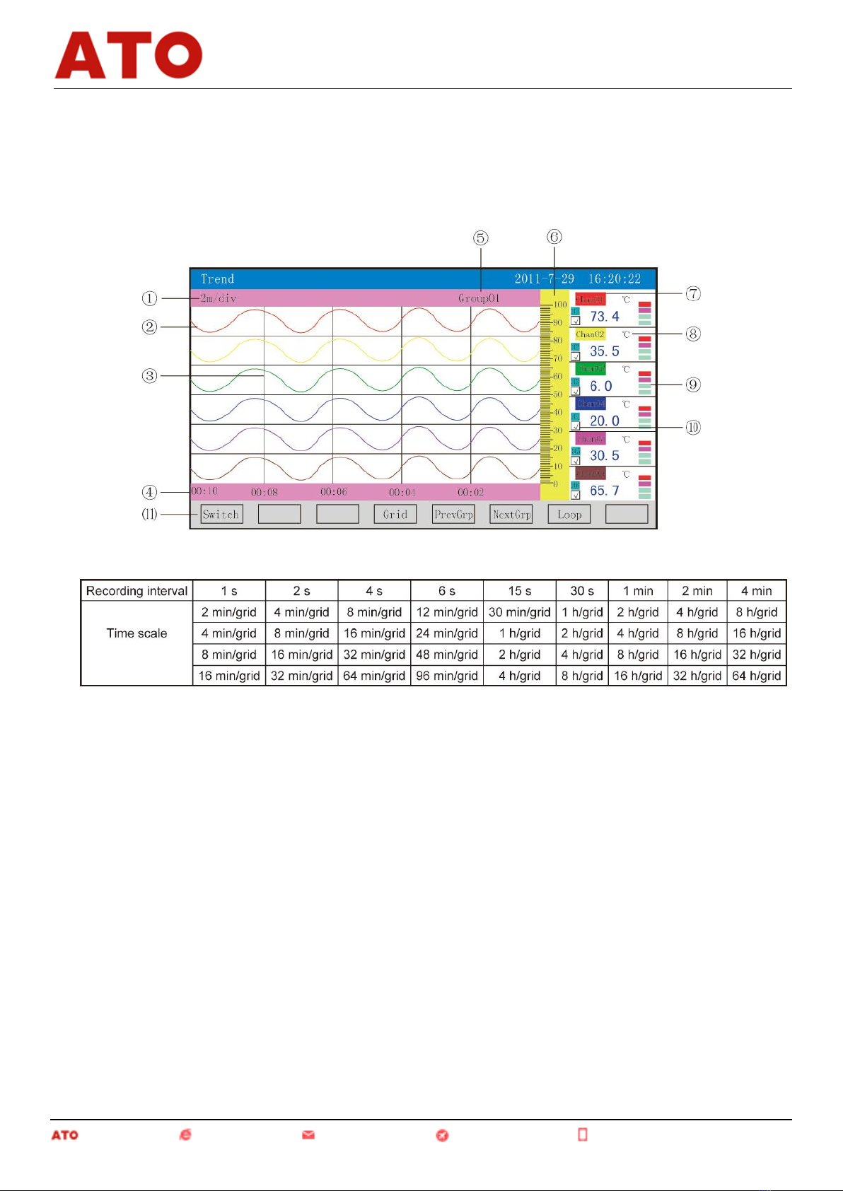
4.3 Real-time Curve Menu........................................................................................................................................6
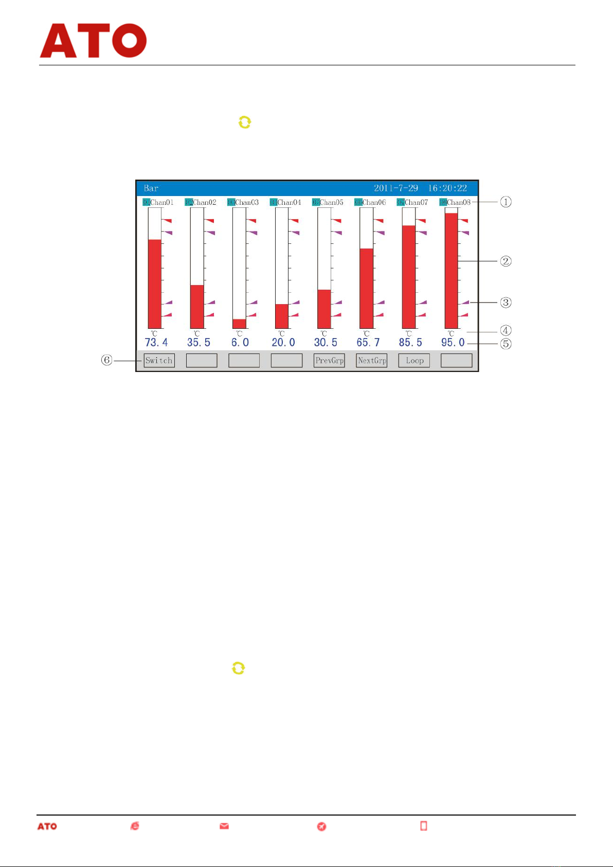
4.4 Bar Graph Menu.................................................................................................................................................7
4.5 Digital Display Menu.........................................................................................................................................7
4.6 Historical Curve Menu.......................................................................................................................................8
4.7 Alarm List Menu........................................................................................................................................... .....9
4.8 File List Menu...................................................................................................................................................10
4.9 Menu for Printing (available for instruments with printing function)..............................................................11
4.10 Menu for Backup (available for instruments with backup function)..............................................................13
4.11 Menu for power-down recording.....................................................................................................................14
4.12 Menu for Configuration...................................................................................................................................15
4.12.1 System Configuration.................................................................................................................................16
4.12.2 Recording Configuration............................................................................................................................17
4.12.3 Displaying Configuration...........................................................................................................................18
4.12.4 Channel Configuration...............................................................................................................................18
4.12.4.1 Introduction of the Input Method of the "Bit Number" of the Channel Configuration.......................20
4.12.4.2 Introduction of the Input Method of the "Unit" of the Channel Configuration...................................24
4.12.5 Analog Output............................................................................................................................................26
4.12.6 Function List..............................................................................................................................................27
V. Communication...................................................................................................................................... ..............27
VI. Instrument Accessories..................................................................................................................... ..................33
I. Overview
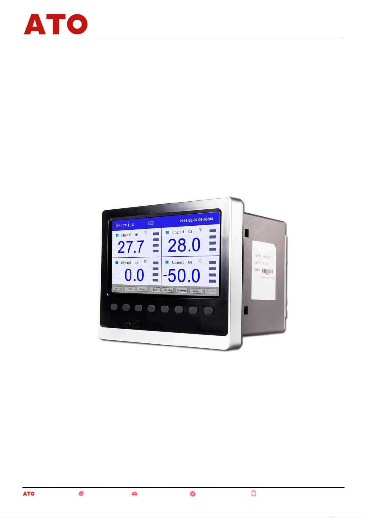
Universal input of color paperless recorder (capable of inputting by means of configuration: standard voltage,
standard current, thermocouple, thermal resistance, millivolt, etc.). It can be equipped with 18-channel alarm
Automation www.ato.com [email protected] Global Shipping +1 800-585-1519 (Toll-free)
Paperless Recorder
1

2
output or 12-channel analog transmitting output, RS232/485 communication interface, Ethernet interface,
mini-printer interface, USB interface and SD card socket; can provide sensor distribution; is equipped with
powerful display function, real-time curve display, historical curve retrospection, bar graph display, alarm list
display, etc. The meter is of high cost effectiveness due to its humanized design, perfect function, reliable
hardware quality and exquisite craft.
II. Main Technical Parameters
Input measurement
Input signal
Current: 0~20mA, 0~10mA, 4~20mA, 0~10mA square root, 4~20mA square root
Voltage: 0~5V, 1~5V, 0~10V, ±5V, 0~5V square root, 1~5V square root, 0~20 mV, 0~
100mV, ±20mV, ±100mV
Thermal resistance: Pt100, Cu50, Cu53, Cu100, BA1, BA2
Linear resistance: 0~400Ω
Thermocouple: B, S, K, E, T, J, R, N, F2, Wre3-25, Wre5-26
Output
Output signal
Analog output: 4~20mA (load resistance ≤380Ω), 0~20mA (load resistance ≤380Ω), 0~
10mA (load resistance ≤760Ω), 1~5V (load resistance ≥250KΩ), 0~5V (load resistance ≥
250KΩ), 0~10V (load resistance ≥500KΩ)
Alarm output: normally open relay contact output, where the contact capacity is 1 A/250 VAC
(resistive load)
(! Note: Please do not carry load directly in case the load exceeds the contact capacity of relay.)
Feed output: DC24 V ±1, load current ≤250 mA
Communication output: RS485/RS232 communication interface, 1,200 ~ 57,600 bps baud rate
(able to be set); standard MODBUS RTU communication protocol is adopted; the communication
distance of RS-485 can be as long as 1 kilometer; the communication distance of RS-232 can be
as long as 15 m; EtherNet communication interface is adopted, where the communication speed is
10 M.
Comprehensive parameters
Measurement accuracy
0.2%FS±1d
Sampling period
1 s
Setting mode
The button is set in the form of panel soft touch; setting values of parameters are
locked with passwords and will be saved permanently in case of outage.
Display method
7-inch 800 * 480 dot-matrix widescreen TFT high brightness color graphics and LCD
display;
LED backlight; with clear pictures and wide visual angle.
Display contents can be composed of characters, figures, conditional curves, bar
graphs, etc.; through panel button, page turning, forward and backward search of
historical data, time scale change of curves, etc. can be realized.
Data backup
Data backup and conversion storage of USB flash disk and SD card are support, where
the maximum capacity is 8 GB; FAT and FAT32 formats are supported.
Storage capacity
The capacity of the internal Flash memory is 64 M Byte.
Recording interval
Nine options including 1, 2, 4, 6, 15, 30, 60, 120 and 140 s can be selected.
Storage length
(continuous record
without power-off)
24 days (1 s interval) – 5825 days (240 s interval)
Automation www.ato.com [email protected] Global Shipping +1 800-585-1519 (Toll-free)
Paperless Recorder

3
Calculation formula: recorded time (day) =
(! Note: For calculation of channel number, the program divides the channel number
into five options, namely 4, 8, 16, 32 and 64, and the bigger figure should be regarded
as the channel number for calculation in case the channel number of the instrument is
between the said two options. For example: If the channel number of the instrument is
12, then 16 should be adopted in the formula.)
Environment condition
Environment temperature: -10 ~ 50°C;
Relative humidity: 10 ~ 90% RH (without condensation of moisture);
Avoidance of contact of high corrosive gas.
(! Note: If the field environment is poor, special instruction should be given when
ordering.)
Working power supply
AC 85 ~ 264 V (power supply of the switches), 50/60 Hz;
DC12 ~ 36 V (power supply of the switches);
power consumption
≤20 W.
III. Notes for Use and Installment
3.1 Notes for Use
3.1.1 Notes for Use of this Instrument
●Please do not make charged goods close to signal terminals for it may result in failure.
●Please do not bring charged items closely to signal terminals as it may result in failure.
●Please do not shock this instrument.
●If you confirm occurrence of such abnormal circumstances as smoke emission from the instrument,
smelling of peculiar smell, abnormal noise sent out by the instrument, etc., please cut off the power supply
immediately and contact the supplier or our company timely.
●To ensure the instrument can operate normally, please power the instrument with electric machine for 30
minutes before using it.
3.1.2 Notes for Use of the External Storage Media
●For storage medium is a kind of precision product, please take care in applications.
●Except from inserting and removing the storage media, please close the operation cover in case of
operating. Contact with the dust should be reduced in terms of the storage media and the USB interfaces to get
protected.
●Please take notice of static protection when using USB flash disk and SD card.
●Products from our company are recommended.
●When using the storage media under high temperature (above 40°C approximately), please insert the
storage medium at the time of saving data, remove it after the data are saved, and do not insert it in the instrument
for a long time.
●Please remove the storage medium before opening/closing power supply.
●For general notes for use of the storage media, please refer to the instruction manual attached by the used
storage medium.
3.2 Instrument Installment
3.2.1 Installment Site
Please install the instrument at the following sites.
●Installment disk
Automation www.ato.com [email protected] Global Shipping +1 800-585-1519 (Toll-free)
Paperless Recorder

4
This instrument is with disk mounted type.
●Installed places
The instrument should be installed in the interior, where wind and rain as well as direct solar radiation should
be avoided.
●Places with good ventilation
To prevent the interior temperature of the instrument from increasing, please install the instrument at the
places with good ventilation.
●Places with less mechanical vibration
Please choose places with less mechanical vibration to install the instrument.
●Horizontal places
Please do not tend to the left or the right when installing this instrument, but should try best to keep
horizontal (able to tend to the back with the maximum of 30°).
-----------------------------------------------------------------------------------------------------------------------------------------
! Note
* When moving the instrument from the place with low temperature and humidity to the place with high
temperature and humidity, if the temperature is under great change, condensation of moisture may sometimes
occur and measurement errors may appear when thermocouple is inputted. In such situation, please adapt to the
surrounding environment for over 1 hour before using the instrument.
* If the instrument is used under high temperature for a long time, the service life of LCD may be shortened
(reduction of image quality, etc.). Please try not to use the instrument under high temperature (above 40°C
approximately).
-----------------------------------------------------------------------------------------------------------------------------------------
Please do not install the instrument at the following places:
●Please choose the places with small temperature change and approximate to the normal temperature
(23℃) to install the instrument. If the instrument is installed at the places that can be directly shined by sunlight or
places near thermal appliances, then bad influences may be imposed on the inside part of the instrument.
●Places with surplus oil smoke, steam, humid gas, dust, corrosive gas, etc.
Oil gas, steam, humid gas, dust, corrosive gas, etc. may impose adverse effects on the instrument.
●Places near galvanomagnetic generating sources
Please do not make magnetic appliances or magnets close to this instrument. If the instrument is installed
near the generating sources of the strong electromagnetic field, the influences brought by the magnetic field may
result in display errors.
To avoid abnormal operation of the instrument, a distance above 20 cm should be kept from the instrument
when radiofrequency generator is used on the spot.
●Places inconvenient to watch images
7-inch TFT true-color LCD is adopted for the display part of this instrument. For display contents cannot be
seen clearly from an extremely eccentric angle, so please install the instrument at the places where observers can
watch from the front face.
3.2.2 Installment Method
●Installment dimensions (Unit: mm)
Automation www.ato.com [email protected] Global Shipping +1 800-585-1519 (Toll-free)
Paperless Recorder

5
●Instrument installment
(1) Instrument method
A. Insert the instrument from the front of the
instrument panel
B. Utilize the installing supports equipped by
the instrument
Installment method is as shown on the
right figure.
▲Two sides of the instrument are fixed by
four installing supports.
(2) Refer to the right figure for the installment
figure.
●Wiring diagram of the instrument
Tail Terminal Figure of the Instrument
Wiring instruction
Automation www.ato.com [email protected] Global Shipping +1 800-585-1519 (Toll-free)
Paperless Recorder

6
IV. Instrument Function and Operation
Color paperless recorder is equipped with multiple operation display menus and configuration menus, where
the displays are clear, the information quantity is large and the configuration is convenient. Users can easily
operate and use the instrument without the need of professional training. After connected to the power supply, the
instrument displays the initial menu, and then enters into the real-time curve menu after the system is initialized.
The following part is an introduction to each operation display menu and configuration menu.
4.1 Switching of Operating Menus
Operating menus are composed of real-time curve menu, bar graph menu, digital display menu, historical
curve menu, alarm list menu, file list menu, menu for printing, menu for backup, menu for power-down recording
and menu of configuration parameters.
The "Switch" key is used to realize switching of each menu.
4.2 Status Display
①: Display name of each operating menu
②: Record mark
"With display" means the file is under cycling recording.
"With display and arrow mark" means the file is not under cycling recording.
"Without display" means the file has stopped recording.
③: SD card mark
"With display" means there is SD card connected.
"Without display" means no SD card is connected.
④: USB flash disk mark
"With display" means there is USB flash disk connected with the instrument.
"Without display" means no USB flash disk is connected with the instrument.
⑤: Cycling display mark
Automation www.ato.com [email protected] Global Shipping +1 800-585-1519 (Toll-free)
Paperless Recorder

7
"With display" means each group is under recycling display.
"Without display" means the menu is fixed without cycling display.
⑥: Display the operating date and time of the instrument
4.3 Real-time Curve Menu
This menu can be set according to the curve combination, and is for simultaneously displaying the real-time
curves and data of six channels (the curve precision is 0.5% ± 1 word).
①: Time scale: It means the length of time per grid and the time scale is related to the recording interval, as
shown in the table below:
②: Data curve: 6 curves can be displayed simultaneously on the common screen at most (6 curve colors,
which can be set through display configuration).
③: Grid: It is for users to estimate time and data values.
④: Time represented by the current grid
⑤: Curve combination: The name of the current curve combination is displayed. (Each curve combination
can include 6 curves; users can put the associated channels into a curve combination according to their own
demands so as to facilitate the comparison of data between channel groups.)
⑥: Scale: The percentile scale of the curves is displayed.
⑦: Channel name: It can be set, and the background color is the same as the color of the corresponding curve.
(Please refer to 4.12.4.1 Input Method of Channel Bit Number for the setting method.)
⑧: Unit: Data unit of such channel is displayed and can be set. (Please refer to 4.12.4.2 Input Method of
Channel Unit for the setting method.)
⑨: Indication of the ultralimit alarm: From the upper to the bottom, the squares represent the ultralimit alarm
marks of ultimate upper limit, upper limit, lower limit and ultimate lower limit respectively; grey means there is
no alarm function; green means not to conduct alarm; red/pink means to conduct alarm.
⑩: Display/hidden mark of curves: "√" means to display the curve, or means to hide the curve.
⑾: Operation keys:
Press the "Switch" key to switch to other displays
Automation www.ato.com [email protected] Global Shipping +1 800-585-1519 (Toll-free)
Paperless Recorder

8
Press the "Time scale" key to switch time scale
Press the "Previous group" key to check the previous curve combination
Press the "Latter group" key to check the latter curve combination
Press the "Cycling" key and the " " cycling icon will be displayed on the menu, and the next curve
combination will be automatically switched according to the cycling interval set in the display configuration.
4.4 Bar Graph Menu
This menu is for simultaneously displaying the data and percent bar graphs of eight channels.
①: Channel name: It means the corresponding project bit number of each channel and can be set. (Please
refer to 4.12.4.1 Input Method of Channel Bit Number for the setting method.)
②: Bar graph: The scale length of the bar graph is 10 grids; filling length of color blocks means the
percentile in the measuring range of the measured values. Blue means the measured value is not under the state of
alarm, while red means the measured value is under state of alarm.
③: Alarm mark
If the ultimate upper limit alarm mark turns red, it means ultralimit alarm is conducted;
If the upper limit alarm mark turns pink, it means ultralimit alarm is conducted;
If the ultimate lower limit alarm mark turns pink, it means ultralimit alarm is conducted;
If the ultimate lower limit alarm mark turns red, it means ultralimit alarm is conducted.
④: Unit: Data unit of such channel is displayed and can be set. (Please refer to 4.12.4.2 Input Method of
Channel Unit for the setting method.)
⑤: Data of quantities: They are the current data of quantities of such channel; blue means the measured
value fails to meet the alarm output, while red means the measured value meets the alarm output.
⑥: Operation keys:
Press the "Switch" key to switch to other displays
Press the "Previous group" key to check the previous bar graph combination
Press the "Latter group" key to check the latter bar graph combination
Press the "Cycling" key and the " " cycling icon will be displayed on the menu, and the next bar graph
combination will be automatically switched according to the cycling interval set in the display configuration.
4.5 Digital Display Menu
This menu is for simultaneously displaying the real-time data and the states of alarm of multiple flow input
channels.
Automation www.ato.com [email protected] Global Shipping +1 800-585-1519 (Toll-free)
Paperless Recorder

9
①: Channel name: It means the corresponding project bit number of each channel and can be set. (Please
refer to 4.12.4.1 Input Method of Channel Bit Number for the setting method.)
②: Data of quantities: They are the current data of quantities of such channel.
③: Indication of the ultralimit alarm: From the upper to the bottom, the squares represent the ultralimit alarm
marks of ultimate upper limit, upper limit, lower limit and ultimate lower limit respectively; grey means there is
no alarm function; green means not to conduct alarm; red/pink means to conduct alarm.
④: Unit: Data unit of such channel is displayed and can be set. (Please refer to 4.12.4.2 Input Method of
Channel Unit for the setting method.)
⑤: Operation keys:
Press the "Switch" key to switch to other displays
Press the "〈—〉" key to switch the channels of the display menus, where the channels include 2, 4, 6, 12, 16
and 24
Press the "2 channels" key to simultaneously display the channel bit numbers, data of quantities, the states of
alarm and the engineering units of 2 channels
Press the "4 channels" key to simultaneously display the channel bit numbers, data of quantities, the states of
alarm and the engineering units of 4 channels
Press the "6 channels" key to simultaneously display the channel bit numbers, data of quantities, the states of
alarm and the engineering units of 6 channels
Press the "12 channels" key to simultaneously display the channel bit numbers, data of quantities, the states
of alarm and the engineering units of 12 channels
Press the "16 channels" key to simultaneously display the channel bit numbers, data of quantities, the states
of alarm and the engineering units of the 16 channels
Press the "24 channels" key to simultaneously display the channel bit numbers, data of quantities, the states
of alarm and the engineering units of the 24 channels
Press the "Previous group" key to check the previous digital display combination
Press the "Latter group" key to check the latter digital display combination
Press the "Cycling" key and the " " cycling icon will be displayed on the menu, and the next digital display
combination will be automatically switched according to the cycling interval set in the display configuration.
4.6 Historical Curve Menu
This menu can be set according to the curve combination, and is for simultaneously displaying the curves of
historical data of six channels (the curve precision is 0.5% ± 1 word).
Automation www.ato.com [email protected] Global Shipping +1 800-585-1519 (Toll-free)
Paperless Recorder

10
①: Time scale: It means the length of time per grid and the time scale is related to the recording interval.
Please refer to the instruction described in 4.3 Real-time Curve Menu for details.
②: Data curve: 6 curves can be displayed simultaneously on the common screen at most (6 curve colors,
which can be set through display configuration).
③: Grid: It is for users to estimate time and data values.
④: Time represented by the current grid
⑤: Curve combination: The name of the current curve combination is displayed. (Each curve combination
can include 6 curves; users can put the associated channels into a curve combination according to their own
demands so as to facilitate the comparison of data between channel groups.)
⑥: Retrospection time: It is written in the type of "year-month-day, hour-minute-second".
⑦: Scale: The percentile scale of the curves is displayed.
⑧: Channel name: It can be set. (Please refer to 4.12.4.1 Input Method of Channel Bit Number for the setting
method.) The background color is the same as the color of the corresponding curve.
⑨: Unit: Data unit of such channel is displayed and can be set. (Please refer to 4.12.4.2 Input Method of
Channel Unit for the setting method.)
⑩: Indication of the ultralimit alarm: From the upper to the bottom, the squares represent the ultralimit alarm
marks of ultimate upper limit, upper limit, lower limit and ultimate lower limit respectively; grey means there is
no alarm function; green means not to conduct alarm; red/pink means to conduct alarm.
⑾: Display/hidden mark of curves: "√" means to display the curve, or means to hide the curve.
⑿: Operation keys:
Press the "Switch" key to switch to other displays
Press the "<< Forward" key to retrospect data forwardly based on the current retrospection time
Press the "Backward >>" key to retrospect data backwardly based on the current retrospection time
Press the "Time scale" key to switch time scale
Press the "Previous group" key to check the previous curve combination
Press the "Latter group" key to check the latter curve combination
Press the "Time" key to modify retrospection time
4.7 Alarm List Menu
This menu is for displaying the alarming records of channels, and is under the state of relay output. At most
100 alarming records can be kept, and the new alarming records will replace the former ones when there are 100
records.
Automation www.ato.com [email protected] Global Shipping +1 800-585-1519 (Toll-free)
Paperless Recorder

11
①: Serial number: It is the serial number for the alarm generated, and is arranged in time order. The smaller
the interval between the occurrences of an alarm, the larger the serial number is.
②: Channel: It is the number of the input channel for the alarm generated.
③: Bit number: It is the corresponding bit number of the input channel for the alarm generated.
④: Alarm time: It means the starting time of an alarm.
⑤: Time of cancelling alarm: It is the end time of an alarm.
⑥: Alarm type: The symbol for ultimate upper limit alarm is "HH", and that for upper limit alarm is "H", for
lower limit alarm "L", for ultimate lower limit alarm "LL".
⑦: Current state of relay: From the left to the right, it means the current states of 1-18 limit relays
respectively; green means the relay contact is off, while red means the relay contact is closed.
⑧: Operation keys:
Press the "Switch" key to switch to other displays
Press the "Up" key to check the alarm list upwardly
Press the "Down" key to check the alarm list downwardly
Press the "Page Up" key to check the alarm list of the previous page
Press the "Page Down" key to check the alarm list of the latter page
Note: 13 alarm records are displayed on one screen in terms of this list.
4.8 File List Menu
This menu is for displaying the stored information and storage states of the files. At most 100 file list records
can be kept, and the new records will replace the former ones when there are 100 records.
Automation www.ato.com [email protected] Global Shipping +1 800-585-1519 (Toll-free)
Paperless Recorder

12
①: Serial number: It is the serial number for the file generated, and is arranged in time order. The smaller the
interval between the occurrences of a file, the larger the serial number is.
②: Starting time: It is the starting time for recording the data of a file.
③: End time: It is the end time for recording the data of a file.
④: Interval: It is the time interval for recording with the recording interval set in the recording configuration
displayed.
⑤: Trigger of recording: It is the condition for triggering of recording with the triggering conditions set in
the recording configuration displayed.
⑥: State: The recording state of the current file is displayed, and the file states are as follows:
Under recording: It means the file is recording data.
Manual stop: It means the file ends recording for the configuration data are modified.
Power-down stop: It means the file ends recording for the instrument is powered off.
Alarm stop: It means the file ends recording for the alarm is cancelled.
Timing stop: It means the file ends recording for the set end time is reached.
⑦: Total time for recording: Calculate the total time for recording.
⑧: Progress bar of storage capacity (Note: It appears when the recording mode in the recording
configuration is non-cycling.)
⑨: Operation keys:
Press the "Switch" key to switch to other displays
Press the "Up" key to check the file list upwardly
Press the "Down" key to check the file list downwardly
Press the "Page Up" key to check the file list of the previous page
Press the "Page Down" key to check the file list of the latter page
Press the "Curve" key to switch to the historical curve menu indicated by the arrow so as to check the
data of the historical curve, and press the "Back" key to return to the file list menu from the historical curve menu
Press the "Backup" key to switch to the backup menu so as to spare single historical file or all historical
file (please refer to 5.10 Backup Menu for the specific operation), and press the "Back" key to return to the file list
menu
Note: 13 stored records are displayed on one screen in terms of this list.
4.9 Menu for Printing (available for instruments with printing function)
The paperless recorder can print historical data and curves with the serial mini-printer connected to the
RS-232 printer port. The baud rate of the printer is "4800" with 8 data bits and no odd-even check
Automation www.ato.com [email protected] Global Shipping +1 800-585-1519 (Toll-free)
Paperless Recorder

13
①: Document No.: recording the serial number of the documents
②: Starting time: starting time of the printing of the data segments
③: End time: end time of the printing of the data segments
④: Printing channel: choose the channel for the printing
⑤: Printing interval: choose the time interval between data printing with the set printing interval * recording
interval as the unit (only effective for data printing)
⑥: Operation keys:
Press the "Switch" key to switch to other displays.
Press the "Up" key to move up the cursor and correct the places the cursor staying by pressing the "OK"
key, and then exit from the display by pressing the "OK" key.
Press the "Down" key to move up the cursor and correct the places the cursor staying by pressing the
"OK" key, and then exit from the display by pressing the "OK" key.
Press "Data" key to print the data of certain time.
Press "Curve" key to print the Curve of certain time
Diagram of the connection of the instrument and the the serial printer:
A: Manual printing
The instrument will start to print data or curve after the "Data" or "Curve" key is pressed.
Recording format of curve printing:
CH1: ℃
End: 11-09-24 10-00-00
Automation www.ato.com [email protected] Global Shipping +1 800-585-1519 (Toll-free)
Paperless Recorder

14
Start: 11-09-24 09-58-00
Data printing formats are as follows:
110924142610:100 ----------------------Measured value of end time
110924142609:100
110924142608:101
110924142607:100
110924142606:100
110924142605:101
110924142604:101
110924142603:100
110924142602:99
110924142601:100 ----------------------Measured value of start time
CH1: ℃ ----------------------Name of channel
B: Timed printing
The printing interval and the starting time of the system configuration should be set for the timed printing, so
the instrument will instrument will control the printer to start timed printing when the system time moves to the
set time interval.
Timed printing formats:
------------------------
CH48:100.0℃-----------------------Measured value of channel 48
CH47:100.0℃-----------------------Measured value of channel 47
..... .....
CH2:100.0℃-----------------------Measured value of channel 2
CH1:100.0℃-----------------------Measured value of channel 1
Time: 10-02-23 14-36-02 -----------------------Date and time
------------------------
Notes: for manual printing, data printing and curve printing are available, while only data printing is
available when choosing timed printing.
4.10 Menu for Backup (available for instruments with backup function)
The paperless recorder can backup and transfer the recorded data in instruments with USB flash disks or the
SD cards. The USB ports are on the front panel of the instruments, and the SD card ports are on the left side of the
instruments. The USB flash disks or the SD cards can be inserted into the instrument after opening the operation
covers for data backup. Automatic backup function of the SD cards: the instrument will back up the historical data
being recorded to the SD cards automatically at 00:00 each day after the SD cards are inserted into the driver; and
the instrument also will back up the historical data to the SD cards automatically when the recording is stopped or
the triggering conditions set out by the users are met.
Storage directory of the documents formed by automatic backup:
1. Storage directory of the documents formed by automatic backup occurred on 00:00 of each day:
TIMEAUTO (file name)/date showed on the instrument (YY/MM/DD)/time showed on the instrument
(hour/minute)
2. Storage directory of the documents formed by automatic backup occurred upon stop of the recording:
RECAUTO (file name)/date showed on the instrument (YY/MM/DD)/time showed on the instrument
(hour/minute)
The users can back up the recorded historical data of all the channels of the instruments to the USB flash
disks or the SD cards with this operation menu. The backup data can be reproduced, analyzed and printed with the
Automation www.ato.com [email protected] Global Shipping +1 800-585-1519 (Toll-free)
Paperless Recorder

15
upper computer software DTM after it is input into computers.
①: Backups: back-up single historical data or all historical data, optional.
②: Document No.: recording the serial number of the documents
③: Starting time: starting time of the data segment backup.
④: End time: end time of the data segment backup.
(Note: the starting time and the end time are automatically generated by the system. The time of the starting
and end time are changeable only for single historical data backup other than backup of all historical data)
⑤: File name/folder name: choose the file name of the data back-upped in the USB flash disk. In case of the
single historical data, the file extension is .NHD; while for all historical data, the folder prefix is F111110.
⑥: If the SD card is not connected to the instrument, the interface will remind the users of "SD card
unavailable", otherwise, there is no prompt and the corresponding icon will be displayed in the status display
column; if the USB flash disk is not connected to the instrument, the interface will remind the users of "USB flash
disk unavailable" after the "Backup" key is pressed, otherwise, the corresponding icon will be displayed in the
status display column.
⑦: Operation keys:
Press the "Switch" key to switch to other displays.
Press the "Up" key to move up the cursor and correct the places the cursor staying by pressing the "OK" key,
and then exit from the display by pressing the "OK" key.
Press the "Down" key to move up the cursor and correct the places the cursor staying by pressing the "OK"
key, and then exit from the display by pressing the "OK" key.
The instrument will display "backup" after the "Backup" key is pressed, and display "backup finished" when
the progress bar of USD ends. The instrument will display "cancelled" and the data backup is stopped when the
"Cancel" key is pressed during the movement of the progress bar.
!Note: in case of all historical data, the parameters will be in shadow, indicating that these parameters are
unable to be set.
4.11 Menu for power-down recording
This menu is used for displaying the relevant records of power-down and power-on time, including the
records of the power-down and power-on time, total power-down times and time. At most 100 alarming records
can be kept, and the new power-down records will replace the former ones when there are 100 records.
Automation www.ato.com [email protected] Global Shipping +1 800-585-1519 (Toll-free)
Paperless Recorder

16
①: Serials number: the serial number of the power-down records ranking in time order and the smaller the
intervals between two occurrences of power-down, the larger the serial number.
②: Power-down time: the time when the instrument is power-down
③: Power-on time: the time when the measurement display of the instrument is turned on after the power is
on
④: Power-down duration: the duration of each power-down
⑤: Total power-down times: the power-down times in total
Total time: aggregation of each power-down duration
⑥: Operation keys:
Press the "Switch" key to switch to other displays
Press the "Up" key to check the power-down record list upward
Press the "Down" key to check the power-down record list downward
Press the "Page Up" key to check the power-down record list of the previous page
Press the "Page Down" key to check the power-down record list of the next page.
4.12 Menu for Configuration
The password comprises 6 numbers and "*"Notes: none of the configuration menus is accessible if the
password is incorrectly set. And the default password is 000000. Hereunder is the brief introduction of each
configuration menu:
Automation www.ato.com [email protected] Global Shipping +1 800-585-1519 (Toll-free)
Paperless Recorder

17
4.12.1 System Configuration
* Language: simplified Chinese and English are available
* Password: the password can be set based on user’s demands
* Date: the time is showed in form of "YY-MM-DD hh:mm:ss". Time can be corrected or adjusted.
* Cold side adjustment: the temperature at the cold side can be adjusted and displayed
* Disconnection handling: lower limit of the measurement range, upper limit of the measurement range and
keeping at previous value are optional
* Address: range: 1 ~ 255
* Baud rate: 1200, 2400, 4800, 9600, 19200, 38400 and 57600 are optional
* IP address: IP address of the Ethernet
* Port: port number of the Ethernet
* Timed printing: the printing time can be set
* Starting time: the starting time of the timed printing can be set
* Alarm printing: turn-on and turn-off are optional
* Data clear: all the data stored in the instrument, including historical data, alarm list, file list, and
power-down list, can be cleared
Operation: in this menu
The cursor can be moved by pressing the "Left" or the "Right" key;
The values can be adjusted by pressing "Up", "Down", "Increase", or "Decrease" key;
"OK" key can be pressed to confirm the execution; the dialogue window of "Are you sure to clear all the
data" will pop up when the cursor is moved to the "Data Clearing" part and the "OK" key is pressed, and press the
"Yes" key to clear data and press "No" key to give up clearing data;
The "Exit" key can be pressed to exit from this menu.
4.12.2 Recording Configuration
Automation www.ato.com [email protected] Global Shipping +1 800-585-1519 (Toll-free)
Paperless Recorder

* Record model: non-cycling and cycling available.
Non-cycling: the cycling recording will stop automatically when there is no recording space left or there are
already 100 records: when the recording space is used up, the recording will continue from the first file and record
the historical data in the circle of replacing the previous files with new files; and when there are already 100 files,
the first file will be deleted at first, the document number of the rest files will be changed to those of the previous
ones, and the new file will be created to continue the recording.
* Recording interval: 1 s, 2 s, 4 s, 6 s, 15 s, 30 s, 1 minute, 2 minute and 4 minute are optional.
* Record type: real-time value, average value, maximum, and minimum are optional.
Real-time value: it is the real-time value corresponding to the recording time.
Average value: it is the average value of the values of two successive recording points calculated with
weighted average calculation method.
Maximum: it is the maximum value of the real-time values of two successive recording points.
Minimum: it is the minimum value of the real-time values of two successive recording points.
* Recording after power-on: new file and before power-down are optional.
New file: the recording is carried out by creating new files after the power is on.
Before power-down: the recording is continued following the files created before power-down; the data
during the outage period is showed as -.—when this function is selected.
* Triggering conditions: manual, power-on, alarm, relay and timing are optional (Notes: the following
changeable triggering methods will be displayed when the corresponding triggering condition is selected)
Manual trigger: the data storage recording can be stopped or started manually after the storage interface of
the instrument is opened.
Power-on: new files will be created and data recording will be started after the power is on and the
instrument is started.
Alarm trigger: the data storage recording will be started when there is certain alarm corresponding to certain
channel, and the recording will be stopped when the alarm ends.
Relay trigger: the data storage recording will be started when certain relay alarms, and the recording will be
stopped when the alarm ends.
Timed trigger: the timed cycle period is fixed at 24 h, and the starting time and end time can be set, so the
instrument will record the stored data within specified period.
Operation: in this menu
The cursor can be moved by pressing the "Left" or the "Right" key;
The values can be adjusted by pressing "Up", "Down", "Increase", or "Decrease" key;
Automation www.ato.com [email protected] Global Shipping +1 800-585-1519 (Toll-free)
Paperless Recorder
18

19
The "OK" key can be pressed to confirm the execution; and the "Exit" key can be pressed to exit from this
menu, the dialogue window of "the recording of the above changes will be stopped and new files will be created
to continue the recording" will pop up, and the "OK" key should be pressed to finally exit from the menu.
4.12.3 Displaying Configuration
* LCD off: 5 m later, 10 m later, 30 m later, 1 h later and Never are optional;
* Cycling interval: the time intervals between the present and the next group of things and there is 4 s, 8 s, 15
s and 30 s optional;
* Startup picture: the real-time curve, bar chart, digital display, historical curve, file list and power-down
record are optional for startup picture
* Curve group: each curve group concludes 6 curves, and there are 10 curve groups available that users can
choose any one based on their demands. The selected curve group will be displayed on the real-time curve menu;
* Start: the curve group will be displayed on the real-time curve menu if "Yes" is selected and will not be
displayed if "No" is selected;
* Curve 1-6: the name of the channel to be displayed, and "Display" and color of the curve should be
selected.
Operation: in this menu
The cursor can be moved by pressing the "Left" or the "Right" key;
The required contents can be selected by pressing "Up", "Down", "Page Down", and "Page Up" keys;
Exit from the menu by pressing “Exit”. The dialog box of “Save changed parameters?” will pop up in case of
any change to the contents, and then select “Yes” to save the changed parameters while select “No” if not.
4.12.4 Channel Configuration
Automation www.ato.com [email protected] Global Shipping +1 800-585-1519 (Toll-free)
Paperless Recorder
Table of contents
Other ATO Measuring Instrument manuals