ATONARP ASTON IMPACT User manual

1
ASTON IMPACT PRODUCT MANUAL, USM-980-0003, REV.A
ASTON IMPACT
PRODUCT MANUAL
April 2022
Software Version: 1.0
Document Version: 1.0

2
ASTON IMPACT PRODUCT MANUAL, USM-980-0003, REV.A
Copyright © 2022 Atonarp Inc.
The contents of this document are protected by copyright laws and
international treaties. Any reproduction, distribution or duplication of this
entire document, or portion of this document, in any form or by any means,
without the prior written consent of ATONARP is prohibited. Additionally, the
contents of this document are protected by contractual confidentiality
obligations. Atonarp products provided are subject to US and Japan Export
Regulations. Transfer of Atonarp products contrary to US and Japan laws is
prohibited.
Atonarp® is a trademark of Atonarp Corporation.
Atonarp U.S. Inc. 5960 Inglewood Dr. Suite 100
Pleasanton, CA 94588, USA
Atonarp Inc.
PMO Shibadaimon 9F, 1-10-18 Shibadaimon,
Minato-Ku, Tokyo
105-0012 JAPAN
Aston Impact Product Manual v. 1.0. 5/20/2022, Software version 1.0

3
ASTON IMPACT PRODUCT MANUAL, USM-980-0003, REV.A
Revision History
Revision
ECO
Change Log
Author
A
ECO-001XX
No content change in this guide
Vinay Kulkarni

4
ASTON IMPACT PRODUCT MANUAL, USM-980-0003, REV.A
TABLE OF CONTENTS
1. Introduction
5
1.1 About Aston Impact
5
1.2 Document Scope
5
1.3 Intended audience
5
1.4 Software release notes
6
1.5 Document version history
6
1.6 Safety guidelines
6
1.7 Notational conventions
6
1.8 Unit conventions
7
1.9 Document support
7
1.10 Customer support
7
2. Specifications
8
2.1 Electrical specifications
8
2.2 Technical specifications
8
2.3 Environmental specifications
9
2.4 Physical dimensions
10
3. Physical Overview
11
3.1 Rear panel
11
3.1.1 Remote IN (DSUB9 Male)
12
3.1.2 Remote OUT (DSUB9 Female)
12
3.2 Side panel
13
3.3 System LEDs
13

5
ASTON IMPACT PRODUCT MANUAL, USM-980-0003, REV.A
4. System Components and Operation
14
4.1 Ion source
14
4.2 Mass filter
14
4.3 Detector
15
4.4 Vacuum (Quadrupole) chamber
15
4.5 Process and pressure measurement and regulation
15
4.6 Quadrupole pressure sensor
16
4.6.1 Pressure sensor specification
16
4.7 Sensor heater
16
4.8 Controllers
16
4.8.1 Main controller
16
4.9 Pumping system
17
5. Legal Information
17
5.1 Liability
17
5.2 Licenses, trademarks, and copyright
17
6. Abbreviations
19
7. Quick Access to Impact Files
20
8. Glossary
21

6
ASTON IMPACT PRODUCT MANUAL, USM-980-0003, REV.A
1. INTRODUCTION
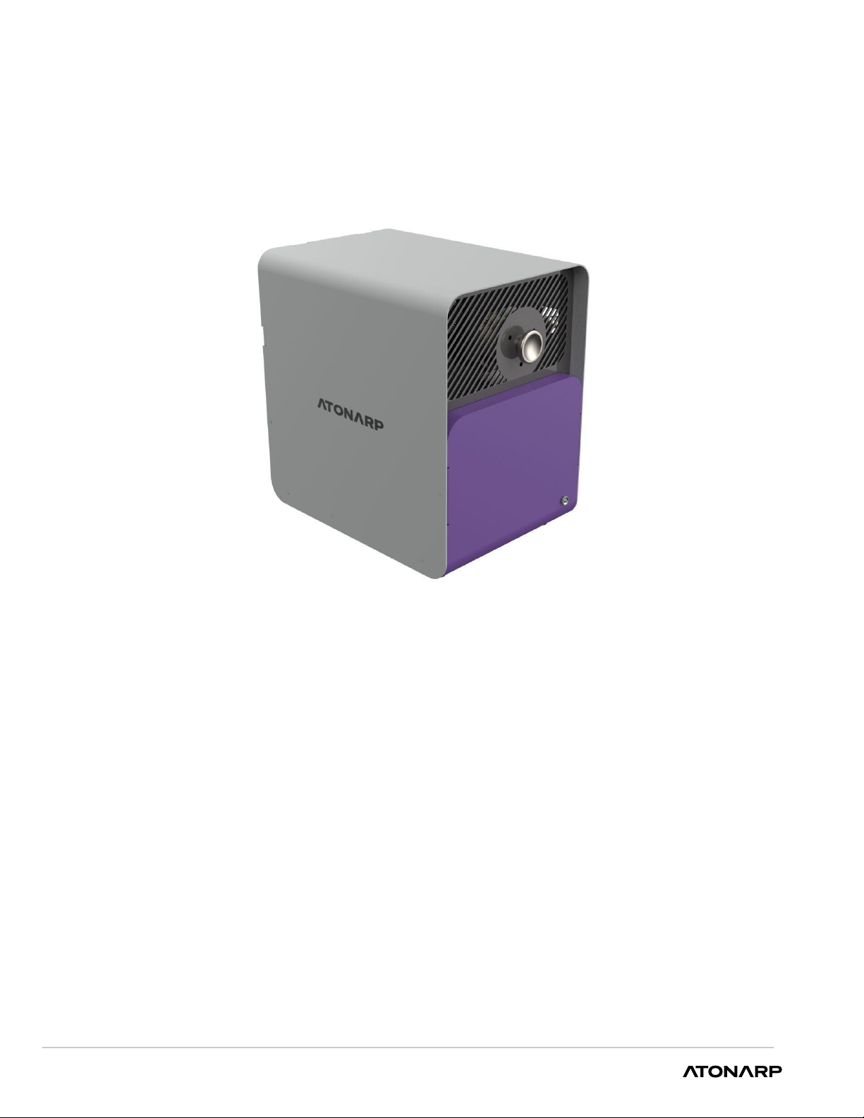
1.1. About Aston Impact
Aston Impact uses mass spectrometry to quantify the composition of constituents in an
analyte by filtering associated ions according to their mass-to-charge ratio (m/z) and
measuring their abundance. A mass spectrum, consisting of ion signal vs m/z is generated.
Within its compact platform, Aston Impact, uses high-performance electronics and
analytical algorithms to display the mass spectrum and compute compositions in real time
without sacrificing response time, sensitivity, resolution, or accuracy.
The result is a highly configurable, quantitative real-time analytical tool which has the
versatility to address many applications in industrial and laboratory environments.
The system is accessible by users through a user interface (UI) called AtonLab. AtonLab is
a feature rich UI providing ample flexibility to customize the system for a desired
application.
AtonLab allows the user to:
● Visualize and control instrument state
● Trigger and visualize data acquisition
● Download and visualize reports
● Configure operating parameters
● Perform instrument calibration
● Run built-in diagnostics
1.2. Intended audience
This document is for the reference of operators who are responsible for setting
up and using the Aston Impact product as part of their process.
1.3. Software release notes
Software release notes with new features, resolved issues, known limitations etc. are
available at the
Atonarp knowledge base
1.4. Safety guidelines
Users must read the general safety information, potential hazards, and associated
warnings for the Aston Impact system. Recommended precautions must be taken to
minimize hazards.
WARNING!
All work described in this document must be carried out by persons who have suitable
technical training and the necessary experience, or who are working under the supervision
of the end-user of the product. Only qualified Atonarp representatives, or Atonarp
approved personnel must install and service the equipment.

7
ASTON IMPACT PRODUCT MANUAL, USM-980-0003, REV.A
1.5. Notational conventions
This manual uses the following typographical conventions
Bold Text
Menus, menu options, function names, input fields,
option icon names, check boxes, drop-down list, dialog
box names, window names, and parameters
WARNING!
Information suggesting possible danger from actions
that can cause failures or injuries
CAUTION!
Recommended care to avoid danger, mistakes or
failures Provides additional
NOTE
Important information about a topic
1.6. Unit conventions
UNIT NAME
SI UNIT
CONVERSION
Pressure
HectoPascal (hPa)
1 hPa = 0.750 Torr = 133.3 Pa
Current
Ampere (A)
1 A = 106µA, 1012 pA,103mA
Frequency
Hertz (Hz)
1 Hz = 10-6 MHz
Capacitance
Farad (F)
1 F = 1012 pF
Temperature
Kelvin
K = 273.15 + °C
The following units of mass are interchangeably used in this document and/or Aston
Impact software - amu, u, Da, Th.
1.7. Document support
Any errors, comments, and questions regarding this document can be communicated
through [email protected]
1.8. Customer support
When issues are encountered with the operation of Aston Impact, or if there are any
queries regarding the product, it is advised to raise a support request at the Atonarp
customer portal available at support.atonarp.com. For more information about the
portal, see customer support document.

8
ASTON IMPACT PRODUCT MANUAL, USM-980-0003, REV.A
2. SPECIFICATIONS
This section describes the electrical and environmental specification details of the Aston
Impact system.
Electrical specifications
Table 1. Electrical Specifications
VOLTAGE
FREQUENCY
MAX POWER
90 – 240V AC
50/60 Hz
250 W
Table 2. Electrical Connection
VOLTAGE
PLUG
110VAC
3 Prong, Grounded plug
230VAC
European style, 2 prong plug with ground contact
Table 3. Inlet Fuse Electrical Characteristics
Ampere
Rating
Percentage of
Ampere Rating
150%
275%
400%
1000%
5A
Opening Time
30 min
600ms-10s
150ms-3s
20ms-300ms
2.1. Technical specifications (See product brochure for latest)
PARAMETER
CONDITION
MIN
TYPICAL
MAX
UNITS
Mass Range
2
300
u
Mass Resolution
Full Width
at 10%
valley for
N2
0.6
0.8
1
u
Mass Number
Stability
0.1
0.1
0.3
u
Sensitivity
(FC/SEM)
Nitrogen-
equivalent
5×10⁻⁶/5×10-4
A/Torr
Minimum
Detectable Partial
Pressure(FC/SEM)
Nitrogen-
equivalent
10-9/10-11
Torr

9
ASTON IMPACT PRODUCT MANUAL, USM-980-0003, REV.A
Limit of detection
Nitrogen-
equivalent
<100
ppb
Maximum
operating
pressure
10-3
Torr
Dwell Time per u
1
40
200
ms
Scan update Rate
per u
37
ms
Sampling
Pressure Range
1×10⁻⁵
1×10⁻³
Torr
Operating
Temperature
80%
relative
humidity
non-
condensing
5
35
℃
Emission Current
0.1
0.4
1
mA
Emission Current
Accuracy
0.03
0.05
0.1
%
Start-up Time
5
mins
Ion current
Stability
Over 24 hrs
at constant
ambient &
pressure
<+/-1
%
Concentration
Accuracy
<2
%
Concentration
Stability
±0.5
±0.5
±1
%
2.2. Environmental specifications
Table 3. Environmental Specifications
SPECIFICATION
VALUE
Indoor/Outdoor
Indoor controlled environment
Relative Humidity
80%, non-condensing
Altitude
max. 2000 m
Ambient Temperature
5 – 35 oC

10
ASTON IMPACT PRODUCT MANUAL, USM-980-0003, REV.A
2.3. Physical dimensions
Aston Impact dimensions are 218 mm wide, 298 mm long, and 314 mm tall
as shown below.
The weight of the Aston impact excluding the cable is 13kg.
If Aston Impact is installed inside a closed enclosure, such as a NEMA enclosure, proper
ventilation using a fan to sustain an air temperature inside the enclosure under 35 oC and
maintaining at least 25.4 mm clearance around the Aston Impact if necessary.
It is also necessary that the users have easy access to the rear side of the Aston Impact, where
the power inlet is located. This is necessary whether the Aston Impact is installed inside an
enclosure or not and will allow easy and quick disconnection of power to the unit if necessary.

11
ASTON IMPACT PRODUCT MANUAL, USM-980-0003, REV.A
3. PHYSICAL OVERVIEW
The physical design of Aston Impact, the various connections and their functions are described
in this section.
3.1 Rear panel
The figure below shows the rear panel of Aston Impact. For a detailed description of the rear
panel interfaces, see the table below. Atonarp recommends that the installation at the user
site be performed by either Atonarp personnel or onsite professionals with knowledge of
vacuum technology aspects. As a reminder, gasses from process chambers simply pass-
through Aston to perform measurements and can be leaked to the ambient atmosphere only
in the case of an outward leak at the exhaust port of the Aston pump. To minimize the
possibility of outward leaks, it is necessary that the system is regularly checked for leakage by
operating it with non-harmful gas and checking for any leak point.
Aston Impact rear panel
Back panel interface description
INTERFACE
DESCRIPTION
Power inlet
Input AC power to the instrument (100-240VAC/ 5A MAX).
Ethernet
A 10/100/1000 Mbps Ethernet interface is provided for high-speed communications
and control. The User interface communicates through this connection.
Ethercat IN
Input port for Ethercat connection
Ethercat OUT
Output port for Ethercat connection
STATUS
LEDs show status of the system (see Table 10)
USB Serial
USB port for troubleshooting through a serial debug interface.
USB – OTG
USB Host or Device (OTG) configurable port. OTG mode is used to program the
Aston. Host mode is to connect peripheral devices.

12
ASTON IMPACT PRODUCT MANUAL, USM-980-0003, REV.A
Remote IN/OUT
Serial input/output connection (See Tables 7 and 8)
TMP Purge
Connection to a N2line to protect turbo pump bearings from corrosive gasses.
Valve 1/2
Optional ports for Open/Close control of the sample line and exhaust line
Exhaust
Gas exhaust from the system.
Pneumatic
(0.4-0.8Mpa)
Optional port for protecting inlet & outlet gas ports, in case of those
pressures are out of our acceptable ranges.
3.1.1 Remote IN (DSUB9 Male)
Table 7. Remote In Pin
PIN. NO
ASSIGNMENT
1
Digital IN (24V) Ch.1
2
Digital IN (24V) Ch.2
3
Digital IN (24V) Ch.3
4
Analog IN (0-10V)
5
24V
6
-
7
-
8
GND
9
-
3.1.2 Remote OUT (DSUB9 Female)
Table 8. Remote OUT Pin
PIN. NO
ASSIGNMENT
1
Analog out (0-5V)
2
Digital OUT (24V) Ch.1
3
Digital OUT (24V) Ch.2
4
Digital OUT (24V) Ch.3
5
24 V (power)
6
GND
7
GND
8
GND
9
GND

13
ASTON IMPACT PRODUCT MANUAL, USM-980-0003, REV.A
3.2 Side panel
Below figure shows the side panel of the Aston Impact system.
Analytes are fed to Aston Impact through the top inlet port on the side panel. The inlet
is a ¼” VCR female connector. There is a second inlet port for the Aston Impact that
can be used as sample bypass for fast response time of the mass spectrometer.
3.3 System LEDs
Functions of various LEDs on the real panel Aston Impact are described. (Lighting:
Normal Status, Blinking: Error Code, x: Lighting or Off)
There is also an LED on the front panel of Aston that turns blue when the power
switch is on, and power is properly supplied to Aston Impact internal components, i.e.
the inlet fuse is not broken.
Table 10. Rear panel LED status description
LED 1
LED 2
LED 3
LED 4
DESCRIPTION
Lighting
X
X
X
CB is powered
Lighting
X
Lighting
X
CB to PC(UI)
Connection is
established

14
14
ASTON IMPACT PRODUCT MANUAL, USM-980-0003, REV.A
4. SYSTEM COMPONENTS AND OPERATION
The core of Aston Impact is the mass spectrometer (MS). Inside the MS, the analyte is
processed in three stages. First, the analyte molecules are ionized in the ion source. The
ions are then filtered according to their mass-to-charge (m/z) ratio in a mass filter. After
filtering, ions of specific mass are captured in a detector which produces an electric
current proportional to the molecule/ion count. The magnitude of the electric current as
a function of mass is plotted as the mass spectrum.
4.1. Ion source
Ionization of the analyte takes place in the ion source. Ionization of analyte molecules is
done to impart a charge to them so that their motion can be controlled by electric fields.
The specific method used to ionize the analyte is called the ionization technique. The
ions produced in the ion source are transmitted by the ion optics into a mass filter. The
polarity of the potentials applied to the ion source and ion optics determines whether
positively charged ions or negatively charged ions are transmitted to the mass filter.
Aston Impact uses electron impact ionization technique as described below.
4.1.1 Electron impact ionization
Electric current is used to heat a filament causing it to emit electrons. The ion source has
electrodes with adjustable bias voltages to create an electric field (typically -70 V) in
which the electrons are accelerated towards the analyte molecules. The high-energy (70
eV for example) electrons collide with the analyte molecules to form molecular ions as
well as doubly charged ions and fragments of lower mass-to-charge values.
Electrostatic lenses in the ion source accelerate/decelerate the transmission of ions
from the ion source to the mass filter. The lens electrode voltages can be adjusted to
control the transmission of ions to the mass filter.
Electron ionization is also useful when the application analytes are not chemically
corrosive (for example, not Cl or F halide gasses).
Filaments are typically made of Tungsten Rhenium alloys. Tungsten is adequate for
chemically reducing environments (for example, H2and SiH4) but vulnerable to oxidation
and hence must not be allowed to be in contact with oxygen. For applications featuring
oxidizing atmospheres (H2O, O2etc.), it is advised to use an Yttria coated Iridium filament.
4.2. Mass filter
The mass filter separates ions according to their mass-to-charge ratio (m/z). At any
specific electric field, only ions of a selected m/z can pass through the mass filter.
The Aston Impact uses a quadrupole mass filter that consists of four cylindrical rods
mounted in a matrix-like pattern in ceramic collar. Ions from the ion source are injected
into the space between the quadrupole rods.
Time varying voltages applied to the quadrupole rods creates an oscillating electric field
through which ions are transmitted. Ions are separated in the quadrupole based on the
stability of their trajectories in this oscillating electric field.

15
15
ASTON IMPACT PRODUCT MANUAL, USM-980-0003, REV.A
Stable trajectories for ions of specific m/z are achieved by applying specific time varying
voltage amplitudes to the quadrupole rods. Ions of other m/z ratios have unstable
oscillations which increase in amplitude until they collide with the quadrupole rods and
are removed from the ion stream.
Each pair of diagonally opposed rods is electrically shorted. A combination of RF and DC
voltages is applied to one pair of rods while the same voltages with opposite polarity are
applied to the other pair. The amplitude of the RF voltage determines the mass-to-
charge ratio of the ions that pass through the mass filter and reach the detector. The
ratio of RF to DC voltage determines the resolution (widths of the peaks).
The filtered ions are focused into the detector. This permits selection of an ion with a
specific m/z or allows the user to analyze a range of m/z values by continuously varying
the applied RF and DC voltages.
4.3. Detector
The detector is located at the exit of the quadrupole mass filter. It receives the ions that
are passed through the mass filter. The detector generates an electronic signal
proportional to the number of ions striking it.
The detector records the charge induced when an ion passes by or hits a surface. In a
scanning instrument such as the quadrupole, a mass spectrum is generated by scanning
RF and DC voltages and recording the ion current at each increment.
Aston Impact uses a Faraday cup (FC) as a detector. The collected charge is converted
to an electric current in a capacitive feedback electro-meter circuit. The electric current
is proportional to the number of ions colliding with it. Because this current is typically
quite small, considerable amplification is necessary to extract a signal.
Optional support for a Secondary Electron Multiplier (SEM) is available. Commercially
available miniature SEM enabling dual mode detection is embedded within the sensor.
The electron multiplier (EM) has an off-axis structure and a Faraday detector for ion
detection. In EM mode, ions emitted from the filter are deflected and multiplied by a
series of dynodes.
4.4. Vacuum (Quadrupole) chamber
The ion sources, ion optics, mass filter and the ion detection system are enclosed in a
vacuum (quadrupole) chamber. A moderate to high vacuum environment is required to
manipulate ions across small distances without colliding with each other or the surfaces
of parts inside the vacuum chamber. Operation at high pressure can also damage the
instrument sensor.
4.5. Process and pressure measurement and regulation
Aston Impact is connected to a process chamber either directly or via an optional
sampling module called Advanced Vacuum Controller (AVC). The AVC regulates the
pressure inside Aston Impact's vacuum chamber, despite process pressure excursions.
The AVC includes a variable leak valve, inlet, and outlet pressure gauges. It throttles the
internal valve to regulate its output pressure which is also Aston Impact's input pressure.

16
16
ASTON IMPACT PRODUCT MANUAL, USM-980-0003, REV.A
4.6. Quadrupole pressure sensor
An integrated cold cathode gauge is used to measure the pressure inside the
quadrupole chamber.
4.6.1 Pressure sensor specification
Table 3. Measuring and pressure value
PARAMETER
SPECIFICATION
Accuracy (N2)
Approx. +/-30%: 1×10 up to 1×100hPa
Approx. +/-50%: 100 to 100 hPa
Repeatability (N2)
Approx. +/- 5%: 1x10⁻⁸ up to 100 hPa
Measuring range (air, N2)
1x10⁻⁹ up to 1000 hPa
Maximum pressure (absolute)
10000 hPa, limited to inert gasses and
temperature < 55 0C
Burst pressure (absolute)
> 1300 Pa
Measuring principle
Cold cathode
4.7. Sensor heater
The sensor heater is used to prevent condensation and adsorption of process species on
the inner walls of the vacuum chamber and on the sensor.
4.8. Controllers
4.8.1 Main controller
The main controller has the integrated drive electronics required to:
• Drive the filament to produce desired emission
• Generate the DC and RF voltages needed to create electric fields between the sensor
electrodes
• Collect data from the ion detector, amplify, and digitize the signal
• Provide computational horsepower needed to run algorithms that post-process the
signal
• Run a web application to provide the user interface for instrument configuration, control,
and reporting
Aston Impact controller supports different scan types to generate, fragment, and eject
ions from the mass filter. The ability to adjust the scan type, and other settings gives
flexibility to adapt it to process requirements.
4.9. Pumping system
A differential pumping system consisting of a turbo-molecular pump and a (optional)
internal roughing pump is used to maintain a moderate to high vacuum in the vacuum
chamber. Split flow turbo molecular pump is clamped to the bottom of the vacuum
chamber. The turbo pump is controlled by a pump control unit.

17
17
ASTON IMPACT PRODUCT MANUAL, USM-980-0003, REV.A
On receiving a signal from Aston Impact controller, the turbo controller initiates the start-
up procedure for the turbo pump. During normal operation, the pump controller monitors
the turbo pump for significant changes in turbo speed, operating temperature, and load
faults. When a fault occurs, the controller will shut off the pump automatically.
5. LEGAL INFORMATION
5.1. Liability
Atonarp assumes no liability and the warranty becomes null and void if the end-user or
third parties:
5.1.1. Do not follow the information provided in this document.
5.1.2. Use the product in a non-conforming manner.
5.1.3. Make any kind of interventions (modifications, alterations etc.) on the product.
5.1.4. Use the product with accessories not listed in the product documentation.
5.2. Licenses, trademarks, and copyright
This section describes the licenses for third party software used or associated with this
product.
Table 36. Software licenses
PACKAGE
COMMENTS
VERSION
LICENSE TYPE
Iniparser
-
-
MIT
Armadillo
-
-
Mozilla Public License
Version 2.0
Libuv
derived out of nodejs
-
BSD
Libwebsockets
statically linked to
unmodified version of
libwebsockets
-
LGPL
Sqlite
-
-
Public Domain
Nlopt
dynamically linked to
operating system
provided library
-
a portion of nlopt
contains GPL
Curl
dynamically linked to
operating system
provided library
-
https://github.com/curl
/curl/blob/ma
ster/COPYING
I2C and SPI driver
-
-
Apache License,
Version 2.0
Nodejs
-
-
MIT
npm packages
body-parser
1.15.2
MIT
cookie-session
1.2.0
MIT
Express
4.14.0
MIT

18
18
ASTON IMPACT PRODUCT MANUAL, USM-980-0003, REV.A
socket.io
1.4.8
MIT
Multer
1.2.0
MIT
Jade
1.11.0
MIT
sqlite3
-
3.1.4
BSD
Websocket
-
1.0.24
Apache License,
Version 2.0
Angularjs
-
-
MIT
Bootstrap
-
-
MIT
This document contains references to the following products from other manufacturers:
5.2.1. ®Windows is a registered trademark of Microsoft Corporation.
5.2.2. ®Swagelok is a registered trademark of Swagelok Corporation.
5.2.3. ®Mac operating system and ®Apple are registered trademarks of Apple Computer
Corporation.
5.2.4. ®Google Chrome and ®Google are registered trademarks of Google Corporation.
5.2.5. ®Intel is a registered trademark of Intel Corporation.
5.2.6. ®Nvidia is a registered trademark of Nvidia Corporation.
5.2.7. ®AMD is a registered trademark of Advanced Micro Devices Corporation.
5.2.8. ®Firefox is a registered trademark of Mozilla.
5.2.9. ®Ubuntu is a registered trademark of Canonical.
5.2.10. Putty is open source certified (BSD License).
5.2.11. ©ISO 7010:2011 (E), Graphical symbols — Safety colors and safety signs —
Registered safety signs.

19
19
ASTON IMPACT PRODUCT MANUAL, USM-980-0003, REV.A
6. ABBREVIATIONS
A
Amperes (current)
Amu
Atomic Mass Unit
BSD
Berkeley Software Distribution
CLI
Command Line Interface
COMM
Communication Port
CTS
Clear to Send
Da
Dalton
dB
Decibel
DB
Database
DC
Direct current
DHCP
Dynamic Host Configuration Protocol
DNS
Domain Name System
EI
Electron Ionization
EHS
Environmental Health and Safety
eV
Electron volt
GND
Ground
GPL
General Public License
HTTPS
Hypertext Transfer Protocol Secure
Hz
Hertz (frequency)
IP
Internet Protocol
IPv4
Internet Protocol version 4
I2C
Inter Integrated Circuit Communications
JPEG
Joint Photographic Experts Group
JSON
JavaScript Object Notation
LED
Light emitting diode
m/z
Mass to charge
Nmtui
NetworkManager Text User Interface
PC
Personal Computer
PDF
Portable Document Format
pF
Picofarads
PNG
Portable Network Graphics
RF
Radio Frequency
RPM
Revolutions per Minute
RS-232
Recommended Standard no. 232
RTS
Request to Send
RX
Receive
SoC
System on a Chip
SSH
Secure Shell
SSL
Secure Sockets Layer
SVG
Scalable Vector Graphics
Th
Thomson

20
20
ASTON IMPACT PRODUCT MANUAL, USM-980-0003, REV.A
TLS
Transport layer security
TTL
Transistor-Transistor Logic
TX
Transmit
U
Unified Atomic Mass Unit
USB
Universal Serial Bus
UI
User Interface
URL
Uniform Resource Locator
V
Volts (voltage)
W
Watts (power)
7. QUICK ACCESS TO ASTON IMPACT FILES
Quick Links to Aston Impact Source Files
1
Atonarp knowledge base
2
Aston Impact Windows client application
3
Aston Impact Ubuntu client application
8. GLOSSARY
Other manuals for ASTON IMPACT
1
Table of contents
Other ATONARP Industrial Equipment manuals
Popular Industrial Equipment manuals by other brands

Camille Bauer
Camille Bauer KINAX N702-INOX HART Programming instructions

Idex
Idex BAND-IT S75099 Owner Manual and Tool Operating Instructions

YASKAWA
YASKAWA DCR-1500 user manual

National Instruments
National Instruments myDAQ user guide

Festo
Festo ELGA-BS-KF-80 instructions

ABB
ABB TZIDC-110 Operating instruction

Graco
Graco VRM 24F872 instructions

SCHUNK
SCHUNK SWG Assembly and operating manual

Altra Industrial Motion
Altra Industrial Motion Warner Electric PB-120 installation instructions

Emerson
Emerson Machinery Health A6500-CC Com Card operating manual

Rose electronics
Rose electronics GT 80/2 Assembling Instruction

GARANT
GARANT SG1 Operation manual