manuals.online logo
Brands
  1. Home
  2. •
  3. Brands
  4. •
  5. ATP Instrumentation
  6. •
  7. Measuring Instrument
  8. •
  9. ATP Instrumentation SL-8851 User manual

ATP Instrumentation SL-8851 User manual

SL-8851
USB Logging Sound Level Meter Manual
Introduction.
This digital logging Sound Level meter is a precision instrument used to meet IEC61672-1 Class 2 Regulations. It
measures sound levels and gives the facility of being able to record and store measured values. When not in use the
instrument should be kept in the carry case to protect it from damage.
Features.
3 Measuring Ranges with Auto Ranging or Manual Range Selection
Over Range and Under Range Indication.
Precision ½” electret condenser microphone.
High accuracy and rapid response.
“A” & “C” Frequency Weighting.
Fast and Slow Response Filters
Data Hold, Min/Max Memory.
56mm High Contrast LCD with 41 Segment Bargraph, Function Indicators and Backlight.
Auto-power Off after 15 minutes with User Disable.
USB output.
Accessories Included: Carry Case, Software, USB Connection Cable, Acoustic Wind Muffler, Mini Tripod and
AC/DC Power Adaptor.
Specifications.
3 Measuring Ranges 30 to 80dB, 50 to 100db, 80 to 130dB or Auto Range 30 to 130dB.
Accuracy: 1.4dB
Sampling rate of 2.5 times per second (selectable rate for logging).
Operating temperature and humidity: 0C ~ 40C and 0%rh ~ 80%rh.
Storage conditions: -10C ~ 50C and 0%rh ~ 70%rh.
Power Source: 1 x 9V battery or AC/DC Adaptor (Supplied).
Meter Dimensions: 290L x 80W x 50H (mm).
Weight of Unit: 350g.
REC
FAST
A/C
1
2
3
4
5
8
6
7
10
9
11
Function Buttons.
11. Power On/Off button.
3. Record Button.
4. Set Up Button.
5. Fast/Slow Response Filters Button.
6. Min/Max Memory Button.
7. Level Button.
8. Backlight Button.
9. A/C Frequency Button.
10. Data Hold Button
DC 9V
OUTPUT
CAL
18
12
13
14
15
16
17
12. AC/DC Adaptor Socket.
13. USB Connection Port.
14. AC/DC Signal Output Port.
15. Calibration Port.
16. 4mm Camera Bush.
17 Battery Cover (Slide).
18 Microphone.
Operating Instructions.
Power On/Off, Auto Power Off and Display Back Light.
To turn the meter on press the yellow power button (No 11) on the bottom of the unit. To switch OFF press and
hold the power button. The display will count down 3,2,1 and then switch off.
At first power on the instrument defaults to a 15 min “Auto Power Off”.
To disable auto power off press and hold Setup button (No 4). This symbol, disappears from the bottom left of the
display. Repeat to re-enable the auto power off.
To illuminate the back light press the button (No 8). Repeat to turn off the back light.
Selection of Measurment Ranges.
To change measurement ranges press the LEVEL button (No 7). The instrument has a default set to 50 - 100dB on
power up. Other ranges available are 80 to 130dB, 30 to 80dB and Auto Ranging from 30 to 130dB. When Auto
Ranging is selected the word AUTO will appear in the bottom right of the display.
To Set Time and Date.
To enter this setup program, press and hold down SETUP button (No 4) and press the Power On button (No 11). The
word ‘Time’ will appear. Press SETUP again. “nn” will appear on the display. This is the minute’s mode. Press LEVEL
button (No 7) to adjust the minutes. Press SETUP again, this is the hour mode, adjust using the LEVEL button. Repeat
to set the Date, Month and Year. Press HOLD button to store the entered data.
To Set Sampling Interval
To enter this setup, press down and hold the back light button (No 8) and the press the Power On button (No 11).
The words ‘INT’ should display as shown in the box below.
It will also show 00:00. To change the sampling rate press Level (No 7) and press Hold (No 10) to save the new
sampling rate. 00:22 means the meter will take a reading every 22seconds and 00:02 is every 2 seconds.
Data Hold.
This function allows the current reading to be frozen on the display. Press HOLD button (No 10) to activate. An indicator
in the bottom of the display will show Hold. Press HOLD again to cancel data hold and the instrument will display
current measured values.
Minimum/Maximum Values.
This function is activated by pressing MIN MAX button (No 6) and will display the minimum and maximum values since
the instrument was switched on. The first value is the maximum measured value with a Max indicator shown in the top
of the display. Press the MIN MAX button again. The displayed value is the minimum measured value with Min indicator
shown in the top of the display. Press MIN MAX again to cancel data hold and the instrument will display current
measured values.
Fast and Slow Response Filters.
This function is used to select the displayed response time to measured values. This is changed by pressing FAST
SLOW button (No 5). An icon appears in the top of the display to indicate which mode is selected. Fast mode displays
measured values updated every 125 milli-seconds. Slow mode displays measured values updated every 1 second.
A/C Frequency Weighting.
This function is used to select the displayed frequency of measured values. This is changed by pressing A/C button (No
9). An icon appears in the bottom of the display to indicate which mode is selected. dBA or dBC.
Acoustic Foam Wind Muffler.
When using the instrument in outdoor applications wind blowing across the microphone can create noise. Fitting the
wind muffler significantly reduces this.
AC/DC Signal Output Earphone Outlet.
OUTPUT
GROUND
OUTPUT
AC
DC
AC/DC Power Adaptor.
The instrument is supplied with a regulated AC/DC adaptor. Do not use any other power adaptor. Prior to connection
slide off the back cover and remove the battery. Connect the adaptor to the instrument the plug in to a mains supply.
Switch on the instrument as normal.
Low Battery Indication.
When the battery power falls below the required voltage a battery symbol will appear on the display. To change
the battery slide the back cover off, disconnect the expired battery and replace.
EPROM Memory Back Up.
The EPROM has a 2nd battery backup so no data is lost due to main battery changes.
Calibration Potentiometer.
This allows the user to make external standard level calibration adjustments. (Only adjust using a traceable calibrator).
This should not be used for traceable calibration adjustments which should be carried out by a qualified technician in a
certified laboratory.
Maintenance and Calibration.
The instrument should be cleaned using a damp cloth to remove any dust or dirt. Do not store the instrument where the
temperatures are excessively low or high or the humidity is excessively high. This should be considered especially when
leaving instruments in vehicles.
Re-calibration of this instrument will vary due to operating conditions and regulations. It is recommended that the meter
is re-calibrated at least once every 12 months. ATP offers a fully traceable calibration service to national standards.
Please call our technical help line for current prices. 01530 566804.
Installing the Software.
Start Windows and insert the CD into the CD drive. Install Wizard should detect and install the software.
If install wizard does not appear automatically go to START at the bottom of the desktop, then Run . . . Browse for
8851(D:) which is the name of the software.
Click on 8851(D:) This will open up the files stored within the CD. Open the SETUP file and follow the instructions to
install the software.
Once this is complete you will see an icon appear on your desktop. The installation was successful, but before you can
use the software you need to install the hardware drivers. Do not remove the CD.
Installing the Hardware Drivers.
You do not need to install the hardware drivers if you already have installed the following ATP Data Logging
Instruments as they all use the same program.
SL-8852 USB Data Logging Sound Level Meter.
LX-1309 USB Logging Lux Meter.
LX-8809A USB Data Logging Lux Meter
With the CD for the software still in the CD drive, turn the instrument on, then connect the meter to the computer using
the USB cable supplied.
A message will appear to show the computer has detected new hardware in the USB port. Double click on this
message. A new window will appear asking you to install the hardware. On this window click ‘No, not this time’, as you
do not need to connect to the windows update. Follow the instructions to install the hardware, but before you press
FINISH check that it reads ‘CP2101 USB Composite Device’ in the window (this is the first hardware driver). Click
FINISH.
The window will now ask to install the hardware; this is to install the second driver. Install in the same way as you did for
the previous driver. In the last window it should show ‘CP2101 USB to UART Bridge Controller’. Click FINISH and
both hardware drivers should now be installed.
To un-install the drivers (in the “add or remove programs”) you will not find two separate drivers. You will find one driver
called ‘CP210x USB to UART Bridge Controller’ this is because both drivers are saved together, so by un-installing
this you are in fact un-installing both the drivers.
Using the Software
Before connecting your meter to your computer turn the instrument on.
To enable the download of logged data the instrument’s measuring range has to be set to ‘AUTO’ ranging. Press the
‘Level’ button (no 7) three times until the word ‘AUTO’ is displayed in the bottom left hand corner of the LCD display.
(Default on the meter is 50 – 100 measuring range).
The ‘AUTO Power Off’ has to be disabled to enable the download of data.
Press the ‘SETUP’ button once to remove this symbol from the bottom left hand corner of the display. If you do
not disable auto power off by removing the clock symbol you will not be able to connect your meter to the software to
download data.
Connect the instrument to the computer with the USB cable. Open the software by clicking on the icon.
Select COM3 from the COM PORT(C) drop down menu.
If there is no connection the software will display No Connection in the instrument image. Check the connections are
correct and plugged in. Check the “Auto Power Off” is disabled.
If the software still displays No Connection create a connection by going to Com Port (C) icon (Top Menu Line), click
and on the drop down menu select Com3 (M). The sound level meter image on the software should now be displaying
the same information as your sound level meter. In some cases this com port will not work and Com4 (4) or another
may have to be selected, by selecting Other Com and choosing the appropriate com port where the information is
being displayed on the sound level meter. This works exactly as it would with Com3 (M) selected.
When the connection is made, the software will show an image of the instrument and display measured values the
same as the instrument.
General Recording using the Software
Open the software and connect the instrument. On the top menu icons, click on RealTime(R). On the drop down menu
click Setup(U). A new window will open.
This window is to set the number of recordings to be made, the real time sampling rate and the recording period. The
sample rate can be set at 0.5, 1, 1.5 or 2 seconds.
Click OK. The software will now log results from the instrument. Note. Data is captured based on the date and time of
the connected computer irrespective of the date and time settings on the instrument.
To stop recording click on RealTime(R). On the drop down menu click Stop(S).
Viewing saved Data.
The graph has a zoom facility. Hold the right button of the mouse near to the area you wish to zoom in on, then drag
and draw a box to cover the data line. On releasing the mouse button the zoom automatically focuses on the selected
area. This can be done 3 times for in depth analysis.
To undo the zoom click the icon in the top of the graph UnDo Zoom.
To save the data for future reference go to File(F), Export Data. This will automatically take you to the Save As window
to save the file as a Microsoft Excel spreadsheet. Before saving the data change the file name from *.xls to an
appropriate name, as it will not allow you to save the data as *.xls.
To save the data as a text file rather than an excel file go to File(F), Save as, and change the file name from *.txt and
press Save.
To delete the data files, press and hold REC, then turn the instrument on. The instrument display will show “CLA” to
indicate the memory has had its data sets deleted.
Trouble Shooting
Meter will not connect
First make sure when you are using the meter with the software that a clock symbol is not showing in the bottom left
hand corner, because this is the symbol that indicates that auto power off is enabled. If this is not disabled by pressing
SETUP on the meter before connecting, you will not be able to connect it at all.
If this is not the case have you worked your way through the different com ports listed on the software. If you have and
none of them work please try the next procedure.
If the hardware has been installed correctly you will be able to find out what com port your meter will work with. To do
this please follow the following instructions, but please note that these instructions were done using Windows 7 so if you
are running a different version of windows it may be in a different place.
Go to START on the tool bar at the bottom of your laptop.
Go to Control Panel and find a computer icon with the word SYSTEM
Double click on this icon and on the left hand side of the System window click on Device Manager.
This will open a window called Device Manager
(this window can be seen on the right hand side):
In the Device Manager list look for Ports (COM &
LPT) and click on the +sign next to it to drop
down a list of the hardware in your computer and
next to each one there will be a COM or LPT
number, this tells you which port or LPT it will
work with. The name of the hardware you are
looking for is Silicon Labs CP210x USB to
UART Bridge and next to this there will be a com
port number. For example on my computer this
hardware will work when com port 4 is selected
on the software.
If the hardware is not listed, this means that the
hardware was not installed correctly. (Please look
at the section for No Hardware Listed in Device
Manager)
If the hardware is listed please make sure that the com port assigned to the hardware is below 10, because the software
will not allow you to connect with com ports higher than this.
When you know what com port has been selected go back to your software, make sure auto power off is disabled on
the meter by pressing SETUP, and select your com port number. If your com port number is higher than 5, select
Other(O) and type in the number (i.e. 6 if its 6 or 9 if it is 9)
If the com port assigned to your hardware is showing as
higher than 10 in Device Manager, please follow the
procedure below.
While you are still in the Device Manager window, right hand click on your hardware to bring up a menu (as seen
below)
Select Properties at the bottom of this menu, to bring up the Properties window for the Silicon Labs hardware.
Then select the Port Settings Tab at the top of the properties window
Now select Advanced at the bottom of the Port Settings window.
In the Advanced Settings window you
can change the com port your meter is
assigned to by clicking on the arrow
next to the current com port (see
picture on the right) and select any com
port below 10. Press OK when you
have changed it on the Advanced
Settings window and Properties
window.
If your software was open during this
change please close it and unplug your meter because the software will not detect the
changes until it is re-opened.
Re-connect your meter, press SETUP to disable auto power off, re-open the software and
connect your meter by select the new com port number.
If the meter still does not connect, repeat the procedure and select another com port
because the one you previously selected could be assigned to a different device already i.e.
memory stick software.
Repeat again if necessary until you find a com port between 1 and 10 that works.
No Hardware Listed in Device Manager
Uninstall the software and see if you can find the hardware listed in the add/remove programs
If you can see it, remove it, so you can re-install everything again.
If you cannot see it, remove just the software and try re-installing everything from scratch.
UK Distributor
ATP Instrumentation Ltd
Tournament Way
Ivanhoe Industrial Estate
Ashby-De-La-Zouch
Leicestershire
LE65 2UU
Tel: 01530 566800 Sales 01530 566804 Technical
Fax: 01530 560373
www.atp-instrumentation.co.uk

Other ATP Instrumentation Measuring Instrument manuals

ATP Instrumentation 1309 User manual

ATP Instrumentation

ATP Instrumentation 1309 User manual

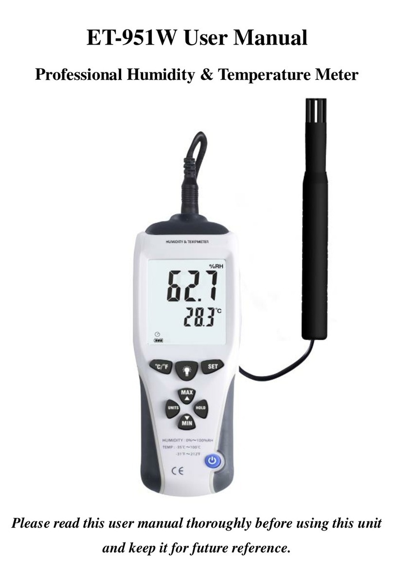
ATP Instrumentation ET-951W User manual

ATP Instrumentation

ATP Instrumentation ET-951W User manual

ATP Instrumentation MT-913 User manual

ATP Instrumentation

ATP Instrumentation MT-913 User manual

ATP Instrumentation LX-1309 User manual

ATP Instrumentation

ATP Instrumentation LX-1309 User manual

ATP Instrumentation 8928 User manual

ATP Instrumentation

ATP Instrumentation 8928 User manual

ATP Instrumentation MT-901A User manual

ATP Instrumentation

ATP Instrumentation MT-901A User manual

ATP Instrumentation IEC61672-1 CLASS2 User manual

ATP Instrumentation

ATP Instrumentation IEC61672-1 CLASS2 User manual

ATP Instrumentation 8820 User manual

ATP Instrumentation

ATP Instrumentation 8820 User manual

ATP Instrumentation AET-951W User manual

ATP Instrumentation

ATP Instrumentation AET-951W User manual

Popular Measuring Instrument manuals by other brands

Valeport miniSERIES Series operating manual

Valeport

Valeport miniSERIES Series operating manual

Charder HM 101M user manual

Charder

Charder HM 101M user manual

NI PXIe-8301 quick start guide

NI

NI PXIe-8301 quick start guide

MFJ MFJ-266B instruction manual

MFJ

MFJ MFJ-266B instruction manual

Keller CellaCast PA8 Series quick guide

Keller

Keller CellaCast PA8 Series quick guide

Rigol DSG3030-IQ user guide

Rigol

Rigol DSG3030-IQ user guide

Georg Fischer Signet 2552 manual

Georg Fischer

Georg Fischer Signet 2552 manual

AXE MMX-L manual

AXE

AXE MMX-L manual

BRUEL & KJAER 4294 user manual

BRUEL & KJAER

BRUEL & KJAER 4294 user manual

T&D TR7 Series quick start guide

T&D

T&D TR7 Series quick start guide

Hioki 9275 instruction manual

Hioki

Hioki 9275 instruction manual

TEKELEK TEK 603 user manual

TEKELEK

TEKELEK TEK 603 user manual

BBC MA 4S user manual

BBC

BBC MA 4S user manual

Hanna Instruments HI770 instruction manual

Hanna Instruments

Hanna Instruments HI770 instruction manual

SevenStar CS200-C user manual

SevenStar

SevenStar CS200-C user manual

BEHA UNITEST 93560 instruction manual

BEHA

BEHA UNITEST 93560 instruction manual

Leica LS10 quick guide

Leica

Leica LS10 quick guide

Circutor CIRWATT Series installation manual

Circutor

Circutor CIRWATT Series installation manual

manuals.online logo
manuals.online logoBrands
  • About & Mission
  • Contact us
  • Privacy Policy
  • Terms and Conditions

Copyright 2025 Manuals.Online. All Rights Reserved.