Atrix APS-4000 Series User manual

APS-4000&APS-7000 series
AC Frequency Conversion Power Supply
User Manual
MATRIX TECHNOLOGY INC.
Chapter 1 Safety Regulations
You should note safety regulations and matters when using it!
Safety signs
Caveat
It reminds users to pay attention to certain operation procedures, practices, conditions and
other matters that may cause personal injury.
Note
It reminds the user of procedures, practices, conditions, etc. that may cause instrument
damage or permanent data loss.
Body ground symbol
Ground symbol
High voltage hazard. (Non-professionals are not allowed to open the machine)
Refer to the warnings in the relevant documents and pay attention to the tips.
(High voltage, please do not touch during operation, beware of touching Electricity, do not use the
machine in unsafe places)
1 Safety instructions
-Before using this AC variable frequency power supply, please read this operating
instruction completely, and fully understand the safety signs used by this machine for
safety.
-Please select the correct input voltage specification before turning on the input power
switch of this machine.
To prevent accidental injury or death, professionals must connect the input or output lines.
When moving and using the machine, be sure to observe clearly before operating■
2 Maintenance
User maintenance
To prevent electric shock, please do not open the cover of the instrument. All parts inside
the instrument absolutely do not require user maintenance. If an abnormal situation
occurs in the instrument, please seek maintenance from our company or its designated
distributor. The attached circuit and block diagram are for reference only.
Regular maintenance
The AC power supply, the relevant accessories of the input power cord, etc. must be
carefully checked and calibrated at least once a year to protect the safety of users and
the accuracy of the instrument.
User modification
The user must not change the circuit or parts of the machine by themselves. If it is
changed, the warranty period of the machine will automatically expire and our company is
not responsible. The use of parts or accessories not approved by our company is also not
guaranteed. If the machine returned for inspection is found to be changed, our company
will restore the circuit or parts of the machine to the original design and charge a repair
fee.
Chapter 2 Installation Essentials
Rules for product unpacking, inspection, preparation before use, and storage.
2.1 Unpacking and inspection
1. Unpack the AC inverter power supply, please check the attached accessories,
Accessories:
1. User Manual
2. Warranty Card
3. Power cable
2. The package of this product is protected by pearl cotton. If the customer receives a
damaged box, please check the appearance of the machine for deformation, scratches, or
damage to the panel.
3. If there is damage, please notify our company or its distributor immediately. And please
keep the packing box and pearl cotton. Our service center will help you repair or replace the
new machine. Do not return the product immediately without notifying our company or its
distributor.
2.2 Check before use
1. Before the input power supply wiring, the power required for this machine, all switches
should be placed in OFF position. Please connect the wiring according to the logo.
2. Please make sure all the wiring is correct before starting.
3. The model will be displayed on the screen when the computer is turned on, and
the CPU will call the last setting value before shutting down, because the setting value has
been memorized in the EEPROM of the machine after leaving each setting state .
Input voltage requirements and options
APS series AC variable frequency power supply uses single-phase 220V power
supply. Before turning on the power switch of the machine, please confirm the choice of
power supply. At the same time, you must use a regular fuse (already equipped at the
factory). The specification of the fuse has been marked on the back panel of the instrument.
Before replacing the fuse, the input power must be turned off to avoid danger.
Input power requirements
Before connected to the input power, power must first confirm the ground line has been
properly connected and also connected to the ground | WARN "on the ground terminal
body. The power plug on the instrument can only be plugged into a power socket with a
ground wire. Such as
I WAKZ1 [If you use an extension cord, you must pay attention to whether it has a ground
wire. This AC variable frequency power supply uses a three-core power cord. When the
cable is plugged into a socket with a ground wire, the body is grounded.
Environmental conditions of use
1. Temperature: 0 o C-40t
2. Relative humidity: W80% RH
3. High degree: at an altitude of 2000 meters above sea level.
4. No gas, vapor, chemical deposit, dust, dirt and other explosive and corrosive media
that seriously affect the machine at the installation site;
5. The installation site should be free from severe vibration or bumps.
2.3 Storage and transportation
Surroundings
APS series AC variable frequency power supply can be stored and transported under the
following conditions:
Ambient temperature the Temp 20C to to 60C
The height of the Height 7620 meters
This machine must avoid abrupt changes in temperature, which may cause moisture to
condense inside the body.
Packing
Original package
Please keep all the original packaging materials, if the machine must be returned to the
factory for repair, please use the original packaging materials. And please contact our
company's maintenance center first. When sending for repair, please be sure to return all
accessories such as the power cord together, please indicate the symptoms and
causes. Also, please note in the package "Easy Scrap" Please handle with care.
Other packaging
If you cannot find the original packaging materials to pack, please follow the instructions
below:
1, first with EPE bag or bubble pack the machine properly.

2, then the machine is placed can withstand 150Kg multilayer carton packaging.
3, around the machine must be filled shockproof material, a thickness of
about 70 to 100mm.
4, properly sealed box.
5, marked "easy and scrap" Please handle with care.
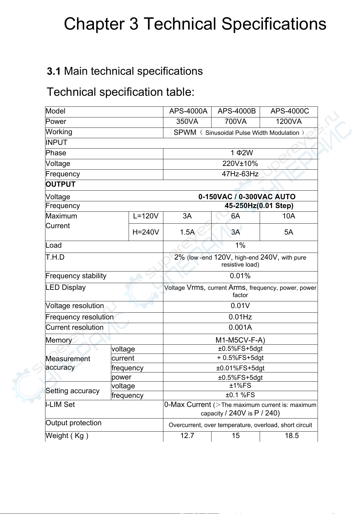
Chapter 3 Technical Specifications
3.1 Main technical specifications
Technical specification table:
Model APS-4000A APS-4000B APS-4000C
Power 350VA 700VA 1200VA
Working SPWM( Sinusoidal Pulse Width Modulation )
INPUT
Phase 1 Ф2W
Voltage 220V±10%
Frequency 47Hz-63Hz
OUTPUT
Voltage 0-150VAC / 0-300VAC AUTO
Frequency 45-250Hz(0.01 Step)
Maximum
Current
L=120V 3A 6A 10A
H=240V 1.5A 3A 5A
Load 1%
T.H.D 2% (low -end 120V, high-end 240V, with pure
resistive load)
Frequency stability 0.01%
LED Display Voltage Vrms, current Arms, frequency, power, power
factor
Voltage resolution 0.01V
Frequency resolution 0.01Hz
Current resolution 0.001A
Memory M1-M5CV-F-A)
Measurement
accuracy
voltage ±0.5%FS+5dgt
current + 0.5%FS+5dgt
frequency ±0.01%FS+5dgt
power ±0.5%FS+5dgt
Setting accuracy voltage ±1%FS
frequency ±0.1 %FS
l-LIM Set 0-Max Current (>The maximum current is: maximum
capacity / 240V is P / 240)
Output protection Overcurrent, over temperature, overload, short circuit
Weight ( Kg ) 12.7 15 18.5
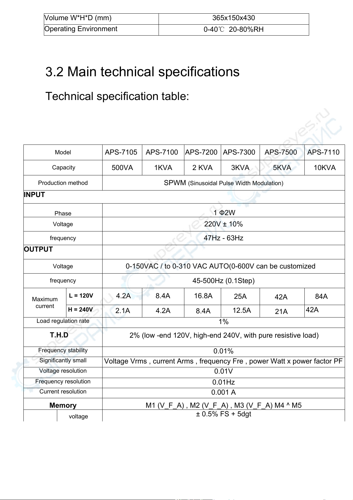
3.2 Main technical specifications
Technical specification table:
Volume W*H*D (mm) 365x150x430
Operating Environment 0-40℃ 20-80%RH
Model APS-7105 APS-7100 APS-7200 APS-7300 APS-7500 APS-7110
Capacity 500VA 1KVA 2 KVA 3KVA 5KVA 10KVA
Production method SPWM (Sinusoidal Pulse Width Modulation)
INPUT
Phase 1 Ф2W
Voltage 220V ± 10%
frequency 47Hz - 63Hz
OUTPUT
Voltage 0-150VAC / to 0-310 VAC AUTO(0-600V can be customized
frequency 45-500Hz (0.1Step)
Maximum
current
L = 120V 4.2A 8.4A 16.8A 25A 42A
H = 240V 2.1A 4.2A 8.4A 12.5A 21A
Load regulation rate 1%
T.H.D2% (low -end 120V, high-end 240V, with pure resistive load)
Frequency stability 0.01%
Significantly small Voltage Vrms , current Arms , frequency Fre , power Watt x power factor PF
Voltage resolution 0.01V
Frequency resolution 0.01Hz
Current resolution 0.001 A
Memory M1 (V_F_A) , M2 (V_F_A) , M3 (V_F_A) M4 ^ M5
voltage ± 0.5% FS + 5dgt
42A
84A
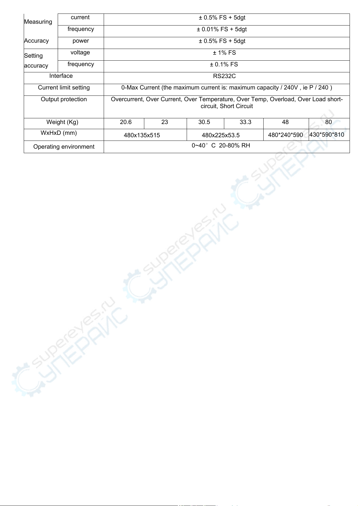
Measuring
Accuracy
current ± 0.5% FS + 5dgt
frequency ± 0.01% FS + 5dgt
power ± 0.5% FS + 5dgt
Setting
accuracy
voltage ± 1% FS
frequency ± 0.1% FS
Interface RS232C
Current limit setting 0-Max Current (the maximum current is: maximum capacity / 240V , ie P / 240 )
Output protection Overcurrent, Over Current, Over Temperature, Over Temp, Overload, Over Load short-
circuit, Short Circuit
Weight (Kg) 20.6 23 30.5 33.3 48 80
WxHxD (mm) 480x135x515 480x225x53.5
Operating environment 0~40°C 20-80% RH
480*240*590 430*590*810
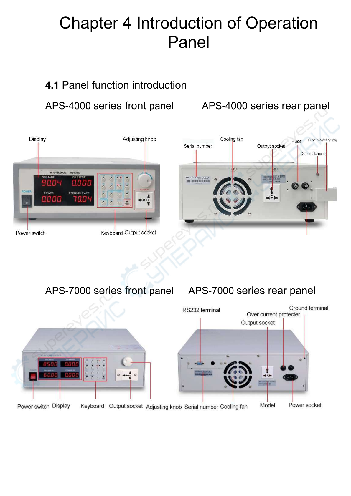
Chapter 4 Introduction of Operation
Panel
4.1 Panel function introduction
APS-4000 series front panel APS-4000 series rear panel
APS-7000 series front panel APS-7000 series rear panel
Chapter 5 Operating Instructions
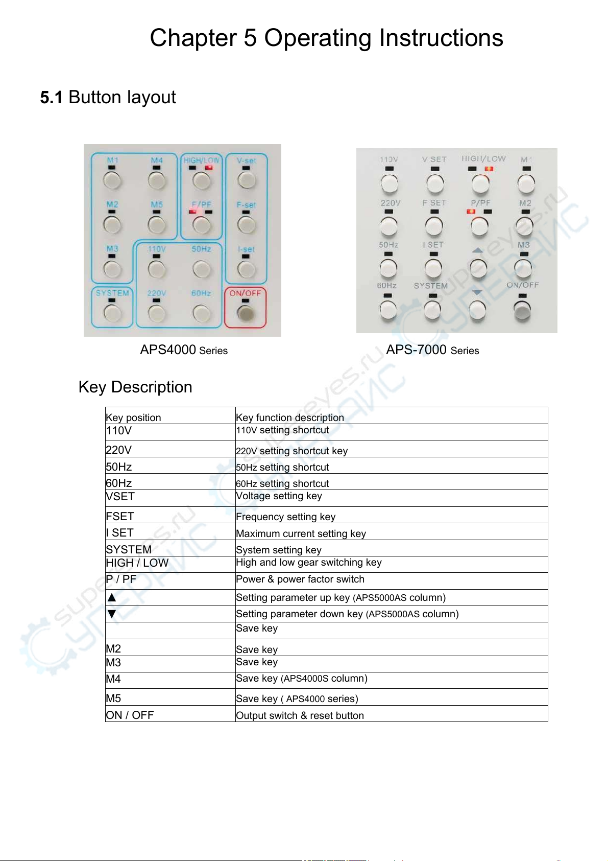
Key Description
Key position Key function description
110V 110V setting shortcut
220V 220V setting shortcut key
50Hz 50Hz setting shortcut
60Hz 60Hz setting shortcut
VSET Voltage setting key
FSET Frequency setting key
I SET Maximum current setting key
SYSTEM System setting key
HIGH / LOW High and low gear switching key
P / PF Power & power factor switch
▲ Setting parameter up key (APS5000AS column)
▼ Setting parameter down key (APS5000AS column)
Save key
M2 Save key
M3 Save key
M4 Save key (APS4000S column)
M5 Save key ( APS4000 series)
ON / OFF Output switch & reset button
5.1 Button layout
APS4000 Series APS-7000 Series
5.3 Voltage setting
In the standby or output state, press the VSET key and or key to adjust the voltage value (APS5000A ^ U only). It
can also be set by adjusting the knob. The voltage range is divided into high and low gears, and the low gear voltage
can be set as 0-150V, the high-end voltage can be set in the range of O ^ OOV; if you want to adjust the voltage
above the low gear, remember to switch the voltage to the high gear to adjust, otherwise the voltage will be displayed
at the highest voltage of the low gear.
The specific operations are as follows:
1. Press the "VSET" key in the standby or output state , the voltage window flashes, at this time you can use the or
key to adjust the voltage value;
2. In standby or output state, press the "V-SET" key. When the voltage window flashes, you can also change the
setting value by turning the knob to the left or right. Lightly press the knob to move the digit you want to set. When you
press continuously, you can move from right to left Circular movement
3. If the voltage setting value is not changed for about 2 seconds, the voltmeter will flash once, and the new
voltage value after memory will be memorized and then automatically leave the setting screen.
5.4 Frequency setting
In the standby or output state, press FSET and or key to adjust the frequency value ( APS5000A ^ column only ). At
the same time, it can also be set by adjusting the knob. In the range of 45 ~ 250HZ, the minimum change is Q1HZ /
STEP, (others are the same as the voltage setting method).
5.5 High and low voltage switching
The voltage high / low switch button, when the low-level output, the rated current of the output is large, and when the
high-end output, the rated current of the output is halved (refer to Chapter 3 Product Specifications). Switching the
high / low range will not affect the voltage setting value, but if switching when the input is ON , the output will be
temporarily powered off (at least 20mS) , and it should be avoided as much as possible. Unreasonable switching will
not be accepted by the Model Version (for example, if the voltage is set to 300V, you want to switch to low gear).
5.6 Current limit setting
Press the ISET key in standby or output state to display the preset current limit value, if you press the "eight" or
key again to adjust the value, (others are the same as the voltage setting method).
When the output current exceeds a set value, the machine buzzer alarm, stops output, ON / OFF of the LED blink,
by ON / OFF for key reset.
5.7 P/PF Selection Key
Press the P / PF selection key at any time to select the power or power factor to be observed.
5.8 ON/OFR
The ON / OFF state of the output can be switched. When the ON / OFF light is on, there is output, and when the
light is off, there is no output. When the output is abnormal, the output will be turned to the OFF state. The ON / OFF
LED indicator flashes. If you press the first button to clear the buzzer alarm, press the second button to reset the error
message and restore the output.
5.9 M1. M2. M3. M4. M5
Five groups of memory modes (three groups for APS5000A series) can store the setting state of voltage and
frequency in any group of memory modes. To memorize, press and hold any key of M1, M2, M3, M4, M5 for more
than one second, the indicator flashes, then it can be stored in the memory. To call / click any one
of M1, M2, M3, M4, M5 You can call the stored memory condition.
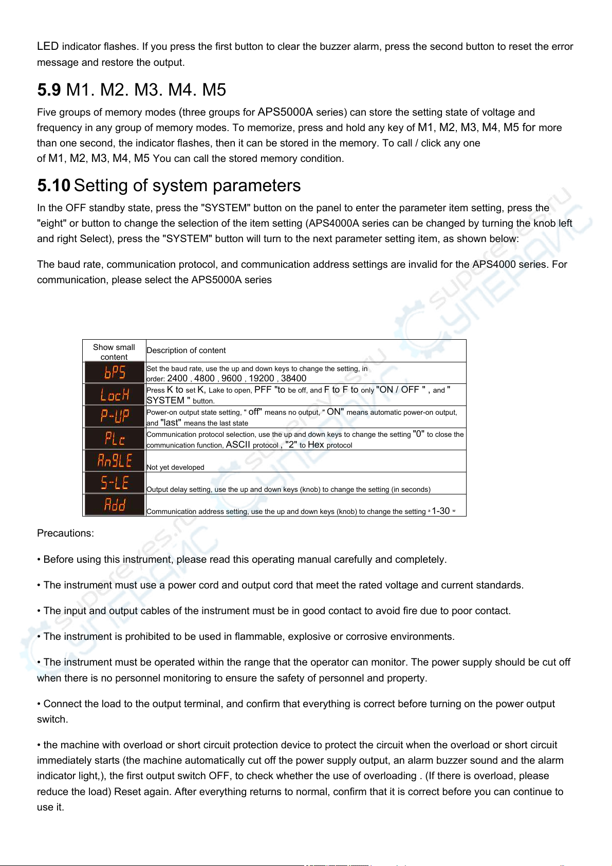
5.10 Setting of system parameters
In the OFF standby state, press the "SYSTEM" button on the panel to enter the parameter item setting, press the
"eight" or button to change the selection of the item setting (APS4000A series can be changed by turning the knob left
and right Select), press the "SYSTEM" button will turn to the next parameter setting item, as shown below:
The baud rate, communication protocol, and communication address settings are invalid for the APS4000 series. For
communication, please select the APS5000A series
Show small
content Description of content
Set the baud rate, use the up and down keys to change the setting, in
order: 2400 , 4800 , 9600 , 19200 , 38400
Press K to set K, Lake to open, PFF "to be off, and F to F to only "ON / OFF " , and "
SYSTEM " button.
Power-on output state setting, " off" means no output, " ON" means automatic power-on output,
and "last" means the last state
Communication protocol selection, use the up and down keys to change the setting "0" to close the
communication function, ASCII protocol , "2" to Hex protocol
Not yet developed
Output delay setting, use the up and down keys (knob) to change the setting (in seconds)
Communication address setting, use the up and down keys (knob) to change the setting a 1-30 w
Precautions:
• Before using this instrument, please read this operating manual carefully and completely.
• The instrument must use a power cord and output cord that meet the rated voltage and current standards.
• The input and output cables of the instrument must be in good contact to avoid fire due to poor contact.
• The instrument is prohibited to be used in flammable, explosive or corrosive environments.
• The instrument must be operated within the range that the operator can monitor. The power supply should be cut off
when there is no personnel monitoring to ensure the safety of personnel and property.
• Connect the load to the output terminal, and confirm that everything is correct before turning on the power output
switch.
• the machine with overload or short circuit protection device to protect the circuit when the overload or short circuit
immediately starts (the machine automatically cut off the power supply output, an alarm buzzer sound and the alarm
indicator light,), the first output switch OFF, to check whether the use of overloading . (If there is overload, please
reduce the load) Reset again. After everything returns to normal, confirm that it is correct before you can continue to
use it.

Chapter 6 Appendix Information
6.1 Fault repair
1. Phenomenon: No voltage output, all display lights on the panel are off.
Reason: No power input
Exclusion: A, check switch is turned on.
B, check the fuse is blown.
C, the input power is properly plugged into the socket or power outage.
2. Phenomenon: No voltage output, frequency meter display flashes, voltage display "0" and buzzer sound
Causes: A, overload or abnormal load.
B, the load starting current is too large.
Exclusion: Turn off the switch, press ON / OFF, after reducing or checking the load, just turn on the output switch.
3. If there is a failure that cannot be eliminated, please notify the maintenance department of our company, and we
will do good after-sales service for you.
6.2 Product maintenance
1. The quality guarantee period of this product is twelve months, during which non-human faults can be guaranteed
free of charge.
2. If the quality guarantee period is exceeded, only Victoria's cost will be charged.
3. Long-term tracking and service, and establish files for customers.
4. Can undertake customized batches and special specifications.
6.3 APS5000A series product communication protocol
Agreement 1
Instruction list:
Integer Reader Command
instruction Parameter range Explanation
?MAXPOW Machine power
?MAXVOL Maximum voltage of the machine
?MAXCUR Maximum current of the machine
?MAXFRE Maximum frequency of the machine
?MINFRE Machine minimum frequency
? MODEL Read machine model
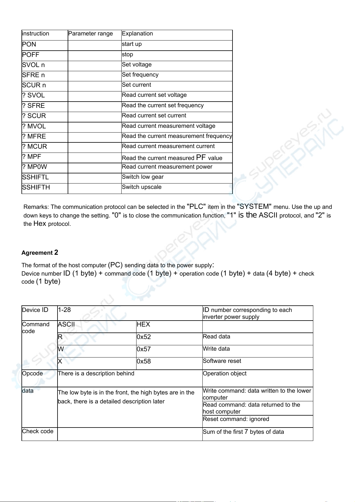
instruction Parameter range Explanation
PON start up
POFF stop
SVOL n Set voltage
SFRE n Set frequency
SCUR n Set current
? SVOL Read current set voltage
? SFRE Read the current set frequency
? SCUR Read current set current
? MVOL Read current measurement voltage
? MFRE Read the current measurement frequency
? MCUR Read current measurement current
? MPF Read the current measured PF value
? MP0W Read current measurement power
SSHIFTL Switch low gear
SSHIFTH Switch upscale
Remarks: The communication protocol can be selected in the "PLC" item in the "SYSTEM" menu. Use the up and
down keys to change the setting. "0" is to close the communication function, "1" is the ASCII protocol, and "2" is
the Hex protocol.
Agreement 2
The format of the host computer (PC) sending data to the power supply:
Device number ID (1 byte) + command code (1 byte) + operation code (1 byte) + data (4 byte) + check
code (1 byte)
Device ID 1-28 ID number corresponding to each
inverter power supply
Command
code ASCII HEX
R 0x52 Read data
W 0x57 Write data
X 0x58 Software reset
Opcode There is a description behind Operation object
data The low byte is in the front, the high bytes are in the
back, there is a detailed description later
Write command: data written to the lower
computer
Read command: data returned to the
host computer
Reset command: ignored
Check code Sum of the first 7 bytes of data

1. The data format of the power supply response to the host computer:
Device number ID (1 byte) + command code (1 byte) + operation code (1 byte) + data (4 byte) + check
code (1 byte)
Device ID 1-28 ID number corresponding to each
inverter power supply
Command
code ASCII HEX
R ' 0x52 Read response
W 0x57 Write response
Opcode There is a detailed description later Operation object
data The low byte is in the front, the high bytes are in the
back, there is a detailed description later
4- byte data returned
Check code Sum of the first 7 bytes of data
Note: The power supply will not return the response command after receiving the software reset command.
2. Instructions
Opcode Function
Description
the data shows Meaning of
reading data
Write data meaning
0x30 Output
status
byte Whether the current is overloaded 1 : Current
overload
0 : normal
0 : clear current overload
sign
Byte 1 Power failure alarm 1 : Power failure
0 : normal
1: Reset to clear the
alarm mark
Byte 2 Is it currently in high-end or low-end
1: high-end
0: low gear
be ignored
Byte 3 Whether to output 1: output
0 : No output
be ignored
0x31 Target
frequency Frequency value of 4 bytes, unit 0.1 H B
range
450-1200
Current
frequency value
Updated frequency value
0x32 High-end
target
voltage
4 -byte value of the voltage, the unit of 0.
The 1V, range
0-3000
Current voltage
value The updated voltage
value, if it was low gear
before, it will also switch
to high gear
0x33 Automatic
target
voltage
4 -byte value of the voltage, the unit of 0.
The 1V, range
0-3000
Current voltage
value The updated voltage
value will switch between
high and low gears
according to the value of
the set voltage. The
standard for the switch is:
set the voltage to 1500
to upshift, otherwise low
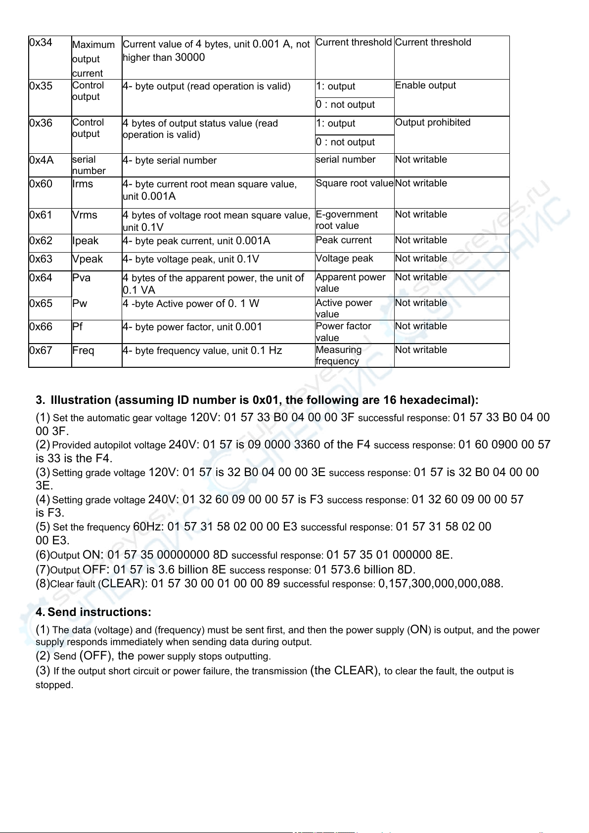
0x34 Maximum
output
current
Current value of 4 bytes, unit 0.001 A, not
higher than 30000
Current threshold Current threshold
0x35 Control
output 4- byte output (read operation is valid) 1: output Enable output
0 : not output
0x36 Control
output 4 bytes of output status value (read
operation is valid)
1: output Output prohibited
0 : not output
0x4A serial
number 4- byte serial number serial number Not writable
0x60 Irms 4- byte current root mean square value,
unit 0.001A
Square root value Not writable
0x61 Vrms 4 bytes of voltage root mean square value,
unit 0.1V
E-government
root value
Not writable
0x62 Ipeak 4- byte peak current, unit 0.001A Peak current Not writable
0x63 Vpeak 4- byte voltage peak, unit 0.1V Voltage peak Not writable
0x64 Pva 4 bytes of the apparent power, the unit of
0.1 VA
Apparent power
value
Not writable
0x65 Pw 4 -byte Active power of 0. 1 W Active power
value
Not writable
0x66 Pf 4- byte power factor, unit 0.001 Power factor
value
Not writable
0x67 Freq 4- byte frequency value, unit 0.1 Hz Measuring
frequency
Not writable
3. Illustration (assuming ID number is 0x01, the following are 16 hexadecimal):
(1) Set the automatic gear voltage 120V: 01 57 33 B0 04 00 00 3F successful response: 01 57 33 B0 04 00
00 3F.
(2) Provided autopilot voltage 240V: 01 57 is 09 0000 3360 of the F4 success response: 01 60 0900 00 57
is 33 is the F4.
(3) Setting grade voltage 120V: 01 57 is 32 B0 04 00 00 3E success response: 01 57 is 32 B0 04 00 00
3E.
(4) Setting grade voltage 240V: 01 32 60 09 00 00 57 is F3 success response: 01 32 60 09 00 00 57
is F3.
(5) Set the frequency 60Hz: 01 57 31 58 02 00 00 E3 successful response: 01 57 31 58 02 00
00 E3.
(6)Output ON: 01 57 35 00000000 8D successful response: 01 57 35 01 000000 8E.
(7)Output OFF: 01 57 is 3.6 billion 8E success response: 01 573.6 billion 8D.
(8)Clear fault (CLEAR): 01 57 30 00 01 00 00 89 successful response: 0,157,300,000,000,088.
4. Send instructions:
(1) The data (voltage) and (frequency) must be sent first, and then the power supply (ON) is output, and the power
supply responds immediately when sending data during output.
(2) Send (OFF), the power supply stops outputting.
(3) If the output short circuit or power failure, the transmission (the CLEAR), to clear the fault, the output is
stopped.

This manual suits for next models
10
Table of contents
Other Atrix Power Supply manuals


