PSU67-3P-1H2-1H0-24250
Weitere Unterlagen
Ergänzend zu diesem Dokument finden Sie im Internet unter www.turck.com
folgende Unterlagen:
■Datenblatt
■EU-Konformitätserklärung (aktuelle Version)
Zu Ihrer Sicherheit
Bestimmungsgemäße Verwendung
Die Spannungsversorgung PSU67-3P-1H2-1H0-24250 ist ein autarkes Schalt-
netzteil für Drehstromnetze im Innenbereich.
Das Gerät darf nur wie in dieser Anleitung beschrieben verwendet werden.
Jede andere Verwendung gilt als nicht bestimmungsgemäß. Für daraus
resultierende Schäden übernimmt Turck keine Haftung.
Allgemeine Sicherheitshinweise
■Nur fachlich geschultes Personal darf das Gerät montieren, installieren,
betreiben und instand halten.
■Das Gerät ist ein Betriebsmittel der„Schutzklasse I” gemäß IEC 61140.
■Das Gerät ist für Bereiche mit Verschmutzungsgrad 3 in kontrollierten
Umgebungen ausgelegt.
■Gerät nur mit zusätzlichen Schutzvorrichtungen im Bereich des Personen-
und Maschinenschutzes einsetzen.
■Das Gerät ausschließlich innerhalb der technischen Spezifikationen
betreiben.
■Das Minuspotenzial eines Ausgangs nicht extern mit PE verbinden.
■Gerät nicht ohne ordnungsgemäßen PE-Anschluss (Schutzerde) verwenden.
Produktbeschreibung
Geräteübersicht
S. Abb.2: Abmessungen, Abb.3: Blockschaltbild
Funktionen und Betriebsarten
Die Spannungsversorgung stellt am Ausgang eine stabilisierte und galva-
nisch getrennte PELV/ES1-Ausgangsspannung zur Verfügung. Das Minuspo-
tenzial des Ausgangs ist im Gerät fest mit PE verbunden.
Der Ausgang ist elektronisch gegen Leerlauf, Überlast und Kurzschluss
geschützt und können jede Art von Lasten versorgen, einschließlich unbe-
grenzter induktiver und kapazitiver Lasten.
Beim Anschluss von Verbrauchern mit einer Kapazität > 100 mF wird der
Ausgang aufgrund von Überlast abgeschaltet. Das Gerät wechselt in den
intermittierenden Modus (Hiccup-Modus) und schaltet den Ausgang nach
dem Beseitigen der Überlast automatisch wieder frei.
Das Gerät ist mit einem Überhitzungsschutz ausgestattet. Bei Übertempera-
tur schaltet das Gerät ab und startet nach Abkühlung automatisch wieder.
Bei einem geräteinternen Fehler begrenzt eine redundante Schaltung die
maximale Ausgangsspannung auf 32,5V. Der Ausgang wird abgeschaltet
und läuft automatisch wieder an, wenn der Fehler beseitigt wurde.
Montieren
Allgemeine Montagehinweise
Das Gehäuse des Geräts garantiert die Schutzarten IP65 und IP67, wenn alle
Gegenstecker fest verbunden sind. Das Gehäuse bietet Schutz vor Schäden
durch elektrische und mechanische Einwirkungen sowie Feuer.
Das Gerät ist generell für den Einsatz in Höhen bis zu 5000m (16400 ft) ge-
eignet. Über 2000m (6560 ft) müssen Ausgangsstrom und Überspannungs-
kategorie reduziert werden.
Bei der Verwendung des Geräts in TN-, TT- und IT-Netzen gilt:
■TN-, TT-Netze mit geerdetem Nullleiter und IT-Sternnetzen mit Isolations-
überwachung: Einsatz in Zonen der Überspannungskategorie III bis zu
einer Höhe von 2000m (6560 ft), Einsatz in Zonen der Überspannungska-
tegorie II bis zu einer Höhe von 5000m (16400 ft)
■TN-, TT und IT-Dreieck-Schutzleitersysteme oder IT-Stern-Netze ohne
Isolationsüberwachung: Einsatz in Zonen der Überspannungskategorie II
bis zu einer Höhe 2000m (6560 ft)
Das Gerät arbeitet mit Konvektionskühlung. Ein externer Lüfter ist nicht
notwendig.
Spezielle Montagehinweise
VORSICHT
Scharfe Kanten auf Geräterückseite
Verletzungsgefahr
➤Geräte auf einer ausreichend großen, ebenen Fläche so montieren, dass
alle scharfen Kanten abgedeckt sind.
➤ Gerät vertikal mit der Anschlussebene nach unten mit je zwei für den
Untergrund geeigneten M4-Schrauben an den oberen und unteren Befes-
tigungslöchern auf einer ebenen Fläche montieren.
➤ Sicherstellen, dass bei der Installation weder Feuchtigkeit noch Schmutz
in die Anschlüsse gelangt.
➤ Bei anderen Montageausrichtungen: Ausgangsstrom reduzieren.
➤ Luftzirkulation nicht behindern. Lüftungslamellen nicht verdecken.
➤ Minimale Montageabstände einhalten: 50mm nach oben und unten,
10mm nach vorne, 10mm links und rechts.
Anschließen
➤ Gerät gemäß„Wiring diagrams”anschließen.
Gegensteckverbinder
■Eingangsspannung (XD1): HANQ4/2, 4 Kontakte + 2 Steuerungskontakte
■Relay-OK-Signal (X0): Standard-M12-Buchse, 5-polig, A-codiert
■Ausgangsspannung (XD2): HANQ4/0
Geeignetes Zubehör finden Sie in der Turck-Produktdatenbank unter
www.turck.com. Das Zubehör ist nicht im Lieferumfang enthalten.
➤ Keine Rücklaufspannungen von einer Last am Ausgang anlegen, die
höher als 35V sind.
➤ Ausgänge oder Geräte nicht parallel schalten.
DE Kurzbetriebsanleitung
© Hans Turck GmbH & Co. KG | 100034423 2022-02
PSU67-3P-1H2-1H0-24250
PSU67-3P-1H2-1H0-24250
IP67 Power Supply
Quick Start Guide
Doc. no. 100034423
Additional
information see
mm [Inch]
HAN-Q4/0HAN-Q4/2
M12 × 1
163.7 [6.45]
168.2 [6.62]
182 [7.17] 59 [2.32]
56.3 [2.22]
232.2
[9.14]
183
[7.21]
107
[4.21]
38
[1.50]
20
[0.79]
4.5
[0.18]
+
–
Output
Power
Manager
Temperature
Shutdown
LED bar
ROK
DC OK
Status
Output
OVP
X0
XD2
Output
3
2
1
4
Set
PFC Power
Converter
Filter
Fuse
Filter
Rectier
L1
XD1
Input
L2
L3
PE
nc
1
2
3
4
5Inrush Current
Limiter
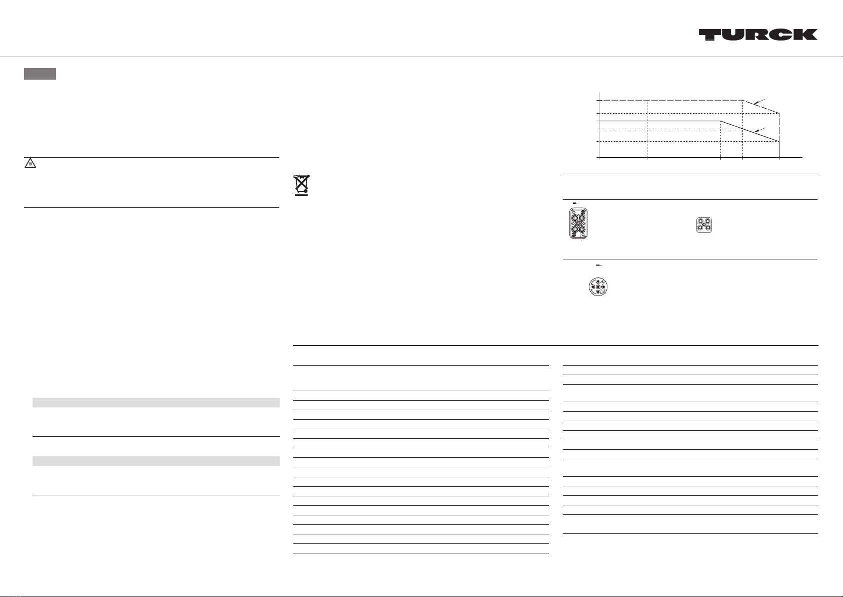
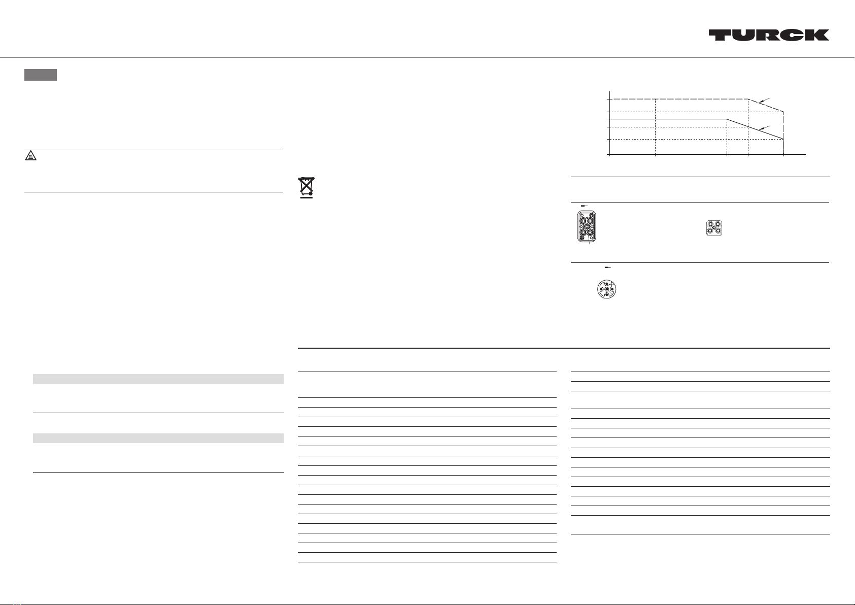
A: continuous current
B: intermittent current
0
12.5 23 27
UOut/V
IOut/A
0
A
B
adjustment range
turck.com