Atronix AX2.88kWhBM User manual
HIGH VOLTAGE BATTERY
Installation
and Operation Manual
AX2.88kWhBM
AX2.88kWhBS
Machine Translated by Google

INTRODUCTION
It contains important regulations and information for the use of this product and provides technical
support for the operator of the device.
The publication and copyright of this documentation remain with the company: AKKU SYS
Akkumulator- und Batterietechnik Nord GmbH Gleitnweg 23
D-25469 Halstenbek Telephone +49 4101
37676-0 • Fax +49 4101 85475-66 • www.akkusys.de • akkusys. shop
Read carefully
before use!
All rights reserved.
Read this instruction manual carefully before installation.
Page 3
3
4
4
4
6
7
7
8
9
9
11
11
12
13
14
16
18 19 21
Our EU declaration of conformity and warranty conditions can be found at: www.a-tronix.de
AKKU SYS Akkumulator- und Batterietechnik Nord GmbH cannot be held responsible for any
inaccuracies or inappropriate information in these operating instructions. The information in this
document is subject to change without notice, but there is no obligation to continually update it.
We reserve the right to make design and device changes that serve to improve the production
process or the product.
Page 2
User manual a-
TroniX AX2.88kWhBM + AX2.88kWhBS
5.1 Specifications BM + BS 5.2
Battery system a-TroniX 2.88kWh BM / BS
Table of Contents 1. Introduction 2.
Symbols 3.
Safety 3.1
Handling 3.2
Installation 4.
Responding to
Emergency Situations 5. Product
Information
22
7.1 Contents of the
package 7.2
Clearance 7.3
Tools 7.4 Installation steps
7.5 Wiring steps 7.6 System
startup 8. Commissioning
9. Exclusion 10.
Troubleshooting
and maintenance 10.1
Maintenance
10.2 Troubleshooting
6. Product features
6.1 Battery system features 7.
Installation
22
23
Machine Translated by Google

Be careful, risk of electric shock.
The battery chemistry of these products is lithium iron phosphate. This manual
Read the instruction manual before starting installation and operation.
a-TroniX AX2.88kWhBS
Install the product out of the reach of children.
Disconnect the device from the power supply before carrying out any
maintenance or repair work.
User manual explain.
is intended for qualified personnel only. The tasks described in this document should
only be performed by authorized and qualified technicians. After installation, the
installer must provide the end user with the
Do not dispose of the product with household waste.
This mark indicates that the requirements for product safety certification are
composite in the UK.
Observe the precautionary measures for handling devices at risk
of electrostatic discharge.
Caution, risk of electric shock, energy storage with time-limited
discharge.
SymbolsSymbol Explanation CE mark. The inverter complies with
the requirements of the applicable CE guidelines.
Protective conductor connection
a-TroniX AX2.88kWhBM
Do not place near flammable or explosive materials.
The document describes the installation, commissioning, maintenance and
troubleshooting of the high-voltage batteries listed below.
Page 3
2. Symbols
1. Introduction
Machine Translated by Google

• Store the device out of the reach of children and animals.
• Do not expose the product to direct sunlight.
• Always handle the battery with insulated gloves.
• Do not connect the storage device to the conductors of the inverter or the
photovoltaic system. This will cause damage to the battery and may result in an
explosion.
• Do not mix up the positive and negative poles of the battery.
• Do not expose the batteries to open flames.
• Do not touch any liquid that comes out of the device. There is a risk of electric
shock or skin injuries.
• Make sure the inverter and battery are completely turned off before beginning
installation.
In the event of an accident, a fire or explosion may occur.
This can lead to damage.
• Store the device in a cool and dry place with sufficient ventilation.
• Do not place the device near combustible materials.
• Do not step on the device or place foreign objects on it.
• Store the product on a flat surface.
• Do not charge or discharge damaged batteries.
• Do not store the device near water sources.
• Do not store batteries near water sources.
• Do not damage the device by dropping it, deforming it, hitting it, cutting it or
penetrating it with a sharp object. This may result in electrolyte leakage or fire.
• After unpacking, check the product for damage and missing parts.
Any work on the batteries should be carried out by authorized technicians. It goes
without saying that technicians should familiarize themselves with the contents of
this manual before carrying out any maintenance or installation work on the system.
3.2 Installation
3.1 Handling
page 4
3. Security
Machine Translated by Google

• Do not connect the battery to an incompatible inverter.
• In the event of fire, only use dry powder fire extinguishers. Liquid fire extinguishers
must not be used.
• Installing the battery outdoors is strictly prohibited.
• Do not use the battery in high static environments where the protection device
could be damaged.
• Do not open the battery to repair or disassemble it. Such repairs may only be
carried out by a-TroniX.
• Do not exceed the permissible battery voltage of the inverter.
• Make sure all batteries are properly grounded.
• Do not install the battery near children or pets.
where the battery can get wet.
• Make sure there is no short circuit between terminals or with an external device.
• Do not connect different battery types together.
• Do not install together with other batteries or cells.
• Do not install the battery near water sources or in places
page 5
Machine Translated by Google

• If it comes into contact with skin, wash the affected area thoroughly with soap and
• If inhaled, please leave the contaminated area immediately and search
In any fire situation, please evacuate people from the building immediately before
attempting to extinguish the fire.
see a doctor immediately.
See a doctor.
• If swallowed, induce vomiting and seek medical attention.
• In case of eye contact, rinse eyes with running water for 15 minutes
The battery modules are not waterproof. Therefore, be careful not to get them wet. If the
battery is fully or partially submerged in water, do not attempt to open it. For further
instructions, contact authorized personnel or a-TroniX.
The battery storage consists of several batteries connected in series. They are designed
to avoid danger or failure. However, a-TroniX cannot guarantee its absolute security.
and see a doctor immediately.
In case of contact with the internal materials of the battery, the user should follow the
following recommendations.
In situations where the battery is on fire, if it is safe to do so, turn off the battery by turning
off the circuit breaker to remove power to the system. Use an FM-200 or CO2 fire
extinguisher for the battery and an ABC fire extinguisher for the other parts of the system.
water location
Fire situation
page 6
4. Responding to emergency situations
Machine Translated by Google

BM
Specifications for AX2.88kWh B.S
5. Product information
Page 7
2.5
(CC-CV) Standard charging current (A)
-20~55
5~95
65
570*380*155
Discharge peak current (60s) (A)
57.6
37.7
50
Normal voltage (V)
Weight (kg)
Max. charge/discharge current (A)
2.88
-10~55
48.6~65.7
Normal energy (kWh)
CAN
50/50
Storage temperature (°C)
25
Max. Continuous Discharge/Charge Current (A)
-10~55
2.5
-20~55
65
Constant current and voltage charge shutdown current (A)
5~95
570*380*170
57.6
31.8
Dimensions (L*W*H) (mm)
50
50
2.88
Normal capacity (Ah)
Communication interfaces
48.6~65.7
Operating temperature (°C)
50/50
Battery voltage range (V)
CAN
50
25
Humidity (%)
5.1 Specifications BM / BS
Machine Translated by Google

Normal voltage (V)
Discharge current (A)
35@-20±2°C @1C;50@25±2°C @0.5C;47@55±2°C @0.5C
230.1
65
* T) [mm]
8.64
Protection class
172.8
Shutdown current (A)
134.7
The number of batteries
20.16
Charge: 0 ~55, discharge: -10 ~55
Normal capacity (Ah)
403.2
50/50
11.52
(CC-CV) Standard
charging current (A)
ÿ6000 @25°C @ 70%SOH
Communication
interfaces
230.4
Discharge peak current
(60s) (A)
Storage temperature (°C)
H
Dimensions
Battery voltage range
(V)
Temperature range (°C)
166.5
1BM+1BS
50
25
(B*
Constant current and
Cycle life
CAN
Normal energy (kWh)
71.1
Characteristics
14.4
-20~55
288
IP65
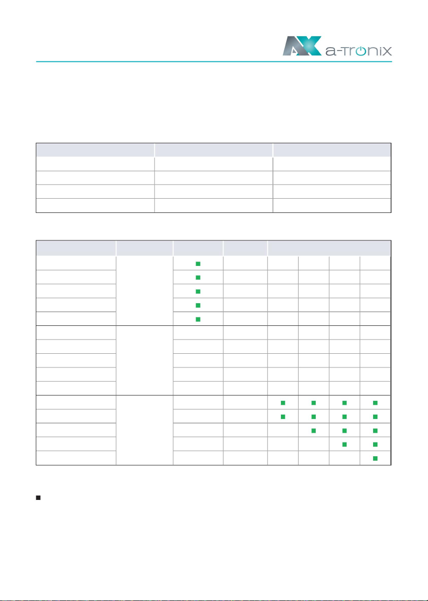
1BM+2BS 1BM+3BS 1BM+4BS 1BM+5BS 1BM+6BS
Max. charging/
Discharge capacity (Ah)
198.3
voltage charge
5.76
2.5
Weight (kg)
115.2
Battery
name*
17.28
Operation
Ingress protection
345.6
Class I
102.9
page 8
IFpP42/151/ 108/[(18S)3S]
108/[(18S)2S]
E/-10+50/90
570*380*350 570*380*470 570*380*590 570*380*710 570*380*830 570*380*950
IFpP42/151/
E/-10+50/90
User manual a-
TroniX AX2.88kWhBM + AX2.88kWhBS
IFpP42/151/IFpP42/151/
E/-10+50/90
IFpP42/151/
E/-10+50/90 E/-10+50/90
108/[(18S)6S]
E/-10+50/90
108/[(18S)4S] 108/[(18S)7S]108/[(18S)5S]
IFpP42/151/
5.2. Battery system a-TroniX 2.88kWhBM + BS
97.2~131.4 145.8~197.1 194.4~262.8 243~328.5 291.6~394.2 340.2~459.9
Specifications for AX2.88kWhBM + BS
Machine Translated by Google

Page 9
6.1 Battery system features
Operating instructions
a-TroniX inverter AX series
BS features:
BM features:
Mounting hole for
bracket
Handle
Right
ground terminal
• Inverter interface protection: over-voltage, over-current, external short-circuit, reverse
polarity, ground fault, over-temperature, over-current
• Interface:
• Battery protection: Internal short circuit, over voltage, over current, over temperature,
under voltage
The batteries are equipped with multiple protection systems to ensure the safe operation
of the system. Some of the protection systems include:
• Interface:
The battery system has the following interfaces so that it can be connected and operated
efficiently.
6. Product features
Machine Translated by Google

Page 10
BMS status LED and SOC LED
DC OUTPUT -
Operating status LED
Bat + connection of the inverter.
at.
POWER switch
Switch to turn on the system, press this switch to start the system.
Connection Bat - of the inverter.
This LED is used to indicate whether the battery is working effectively. A green light on this LED means the
battery is on and functioning normally. If the battery is not functioning properly, a red glow on this LED means
the battery is not functioning properly.
DC switch
After switching on, press this button for 5 seconds.
B start switch
DC OUTPUT +
The LEDs show specific alarm information and the performance of the battery system
Power switch, battery charge and discharge switch.
Machine Translated by Google

Page 11
For BM
For BS
Article
Article
Article
7. Installation
Number
Number
Number
7.1 Contents of the package
Fast-
J
Footrests Wall mounting screw set
RJ45 connector
L
D mounting bracket
Waterproof cover
A
Communication cable
H DC output cable
Fast-
EK
Quick installation guide and user
manual
F
Fastening screw set
(BMS inverter)
Installation
Guide
G ground cable
b
Installation
Guide
C Fastening screw set I
Quick installation guide and user
manual
Please check whether the following parts are included in the packaging:
ED
A
G
F
J
b
H
KL
I
C
Machine Translated by Google
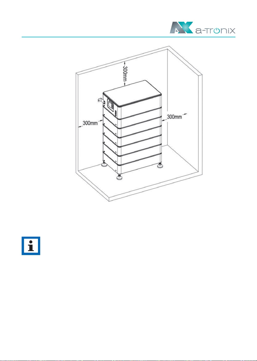
7.2 Free space
Make sure there is at least 300mm of clearance. A distance of at least 300mm must
be maintained around the battery pack to ensure cooling.
NOTE
Make sure that the battery pack is always exposed to the ambient air. The
battery pack is cooled by natural convection.
If the battery pack is fully or partially covered or shielded, this may cause
the battery pack to stop functioning.
page 12
Machine Translated by Google

7.3 Tools
The following tools are required for installation.
Modular
Rail level level
Crimping
drilling machine
multimeter
marker
Safety gloves
Safety shoes
duct tape
Ribbonsafety goggles
screwdriver
Electrical
Tongs
Page 13
Machine Translated by Google

7.4 Installation steps
Step 1:
Install a BS with four footrests (Item E), place it on the floor and adjust the height. After
installing the foot stand, use a spirit level to check the leveling. Insert the waterproof cover
(Item K) into the bottom of the batteries and lock it with the clip.
Step 2:
Place the battery 20mm against the wall.
Make sure the power status LED is on the left when looking at the battery model.
A NOTICE
Page 14
Machine Translated by Google
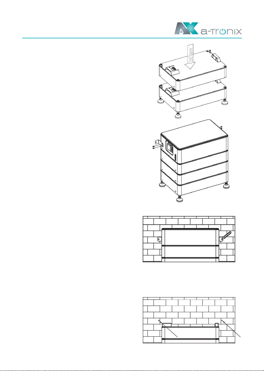
near the wall and mount it on both sides of the battery.
Step 4:
Attach the two mounting brackets (pos. D)
Step 6:
Drill the holes with an electric drill, make sure the holes are at least 50mm deep, and
then tighten the expansion tubes (Item J).
Step 5:
Mark the wall through the hole in the bracket.
Step 3:
Stack the batteries one by one.
Page 15
Machine Translated by Google

For outdoor use, please
use item L and follow the steps below
A NOTICE
NOTE
Please make sure each system contains 1 BM and 1
BS. BS max. 6 pieces.
For the wiring of the inverter, please refer to the inverter user manual.
Connect the inverter to ensure the wiring is correct as shown in the figure below.
Step 8:
Attach the screw packs (Item C) on both sides of the battery
and the installation is complete.
Step 1:
Prepare a standard network cable and cable connector and feed the network cable through the cable
connector.
A:
Step 7:
Attach the battery to the wall.
Steps to connect:
Page 16
7.5 Wiring steps
Machine Translated by Google
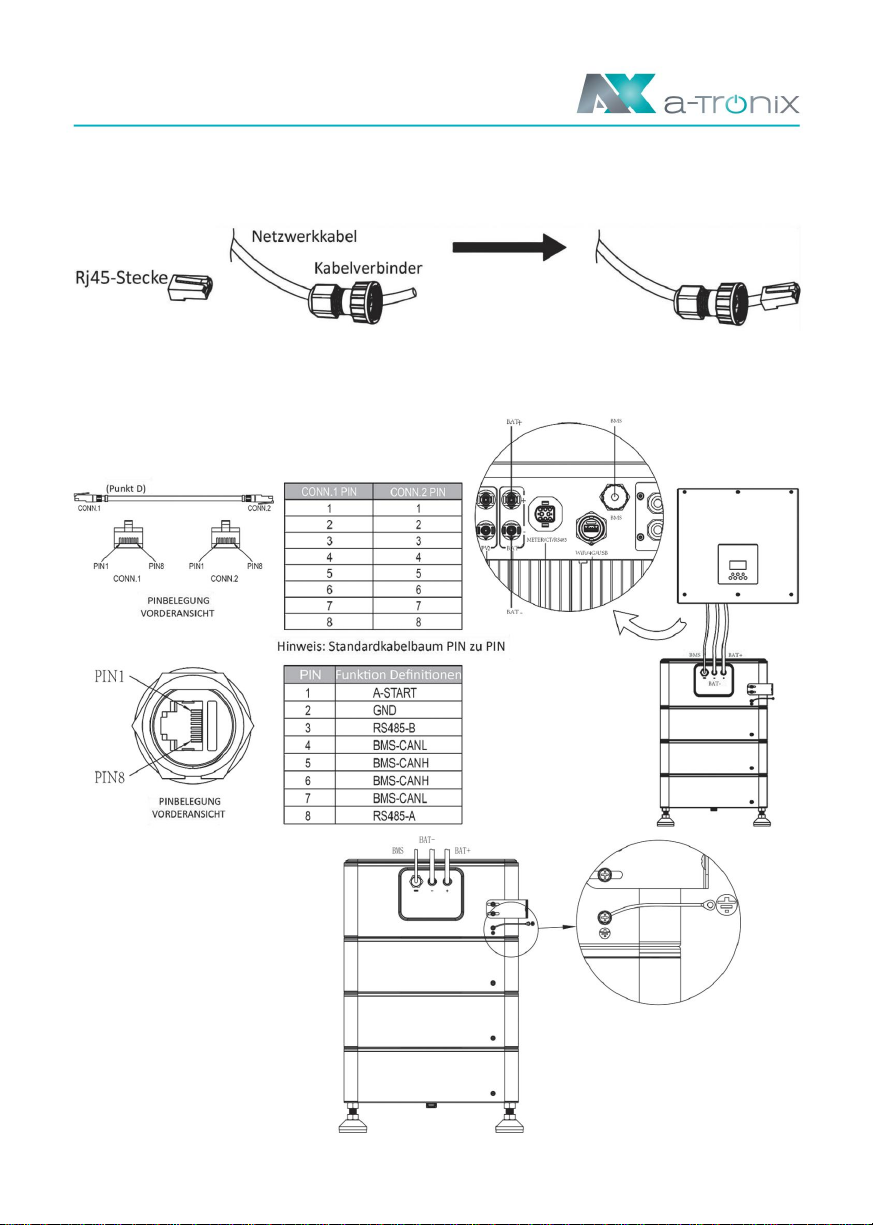
Step 3:
Insert the cable connector into the BMS port on the
bottom of the inverter and screw it tight.
Connect the ground wire to ensure
all batteries are grounded. The
wiring must be connected in the
order shown below.
B:
Step 2:
Crimp the cable with an Rj45 connector located inside the cable connector.
If used indoors, please use point F
Page 17
Machine Translated by Google

1. Turn on the POWER switch.
7.6 System startup
Page 18
• When the grid-connected system is put into operation, the inverter should be turned on
first to avoid the current pulse of the inverter increasing to the battery pack.
• All installations and operation must comply with local electrical standards
• Check all power cables and communication cables carefully.
are equivalent to.
• Turn on the DC switch and press the POWER switch, first the mater LED lights up
once, then the BMS status LED lights up for 0.5s, the operating status LED lights up
for 1s at the same time, that means the system is working normally.
Machine Translated by Google
Page 19
For BM
For BS
8. Commissioning
25% > SOC >= 0%
•
•
•
•
•
•
/
status Green LED Red LED
•
•
On for 1s, off for 1s
50% > SOC >= 25%
•
/ /
On for 0.1s, off for 0.1s
75% > SOC >= 50%
/ / /
•
On for 0.5s, off for 0.5s
Normal business. Business as usual
75% > SOC >= 50%
•
=100%
/
/
LED4-1
•
•
/
25% > SOC >= 0%
•
•
•
•
•
On for 1s, off for 1s
•
•
standby
•
•
50% > SOC >= 25%
•
/ / /
alarm
•
•
•
On for 0.1s, off for 0.1s
100% > SOC >= 75%
•
=100%
/ / / / / / / / / / /
/
Charge
Out of
Runs in the boat
=100%
/ / /
•
50% > SOC >= 25%
•
•
•
Out of
75% > SOC >= 50%
25% > SOC >= 0%
/ /
•
Unloading
•
On for 0.5s, off for 0.5s
100% > SOC >= 75%
/
•
•
•
To update
100% > SOC >= 75%
•
/ / /
•
Battery statusRed LED
Green LED
SOC
The operating status light on the left side of the battery pack indicates the operating
status.
Remark:
LED flash display (on: 0.5s, off: 0.5s)
• LED display
Machine Translated by Google

LED4-1
• •• •
Mistake
Page 20
•
/
SOH protection low
/
Overcurrent when discharging
/
•
•
•
/
•
•
/ / /
HVB FUSE error
•
•
•
•
•
Relay sticks
/
•
Temperature sampling failed
•
The individual high voltage has
failed permanently
/
•
•
/
/
/
•
•
•
•
/
•
•
•
Discharge over performance
•
•
/
•
/
•
•
Shutdown failed
/
/ / / / / / / / / /
•
AFE communication failed
•
•
/
•
•
Performance failed
•
/
/
/
Charge via electricity
•
/
•
•
AFE failed (UV/OV/UT/OT)
•
•
Module FUSE error
/
•
•
/ / / /
Relay not closed
/ /
•
•
/
•
Single cell “0V” error
•
/ / /
•
Subpoena failed
•
•
/ /
•
IVU communication failed
/
/
/
/ / /
•
•
Internal
/
•
•
/ /
Relay drive failed
•
/
Charge over performance
•
•
•
•
•
Other error
•
•
•
/ / / / / / /
Module addressing failed
•
/ /
/
/
•
•
/ / /
•
•
•
PCS communication failed
•
/ /
•
Undertemperature error
/
/
/
•
/ / /
/
/ /
•
/ / / /
•
•
/
/
•
BMU communication failed
Short circuit protection
Temperature high
permanently failed
Total voltage sampling failed
Undervoltage fault Overvoltage
fault Overtemperature fault
•
/
Green LED Red LED
Machine Translated by Google
Other manuals for AX2.88kWhBM
1
This manual suits for next models
1
Table of contents
Other Atronix Batteries Pack manuals

Popular Batteries Pack manuals by other brands

HEINE
HEINE EN 50UNPLUGGED manual

Panasonic
Panasonic CF-VZSU32U operating instructions

Blue Sky Network
Blue Sky Network SKYLINK quick start guide

EnerSys
EnerSys SuperSafe SBS XC Installation, operation and maintenance manual

LG
LG BLGRESU10HP installation manual

Tripp Lite
Tripp Lite BP72V15-2U Specification sheet


