1.2 General Precautions
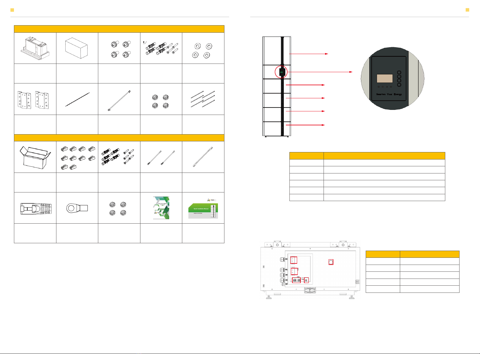
1.3 Parts List
Check the following parts list to ensure it is complete.
AlphaESS delivers a total system separately on site to client, this consists of:
INTRODUCTION INTRODUCTION
DANGER
CAUTION:
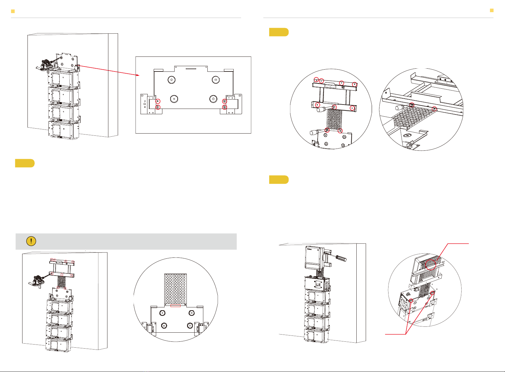
SMILE-T10_INV
Danger to life due to high voltages of the PV array, battery and electric shock.
When exposed to sunlight, the PV array generates dangerous DC voltage which will be
present in the DC conductors and the live components of the inverter. Touching the DC
conductors or the live components can lead to lethal electric shocks. If you disconnect the DC
connectors from the system under load, an electric arc may occur leading to electric shock
and burns.
Do not touch uninsulated cable ends.
Do not touch the DC conductors.
Do not open the inverter and battery.
Do not wipe the system with damp cloth.
Have the system installed and commissioned by qualified people with the appropriate skills
only.
Prior to performing any work on the inverter or the battery pack, disconnect the inverter
from all voltage sources as described in this document.
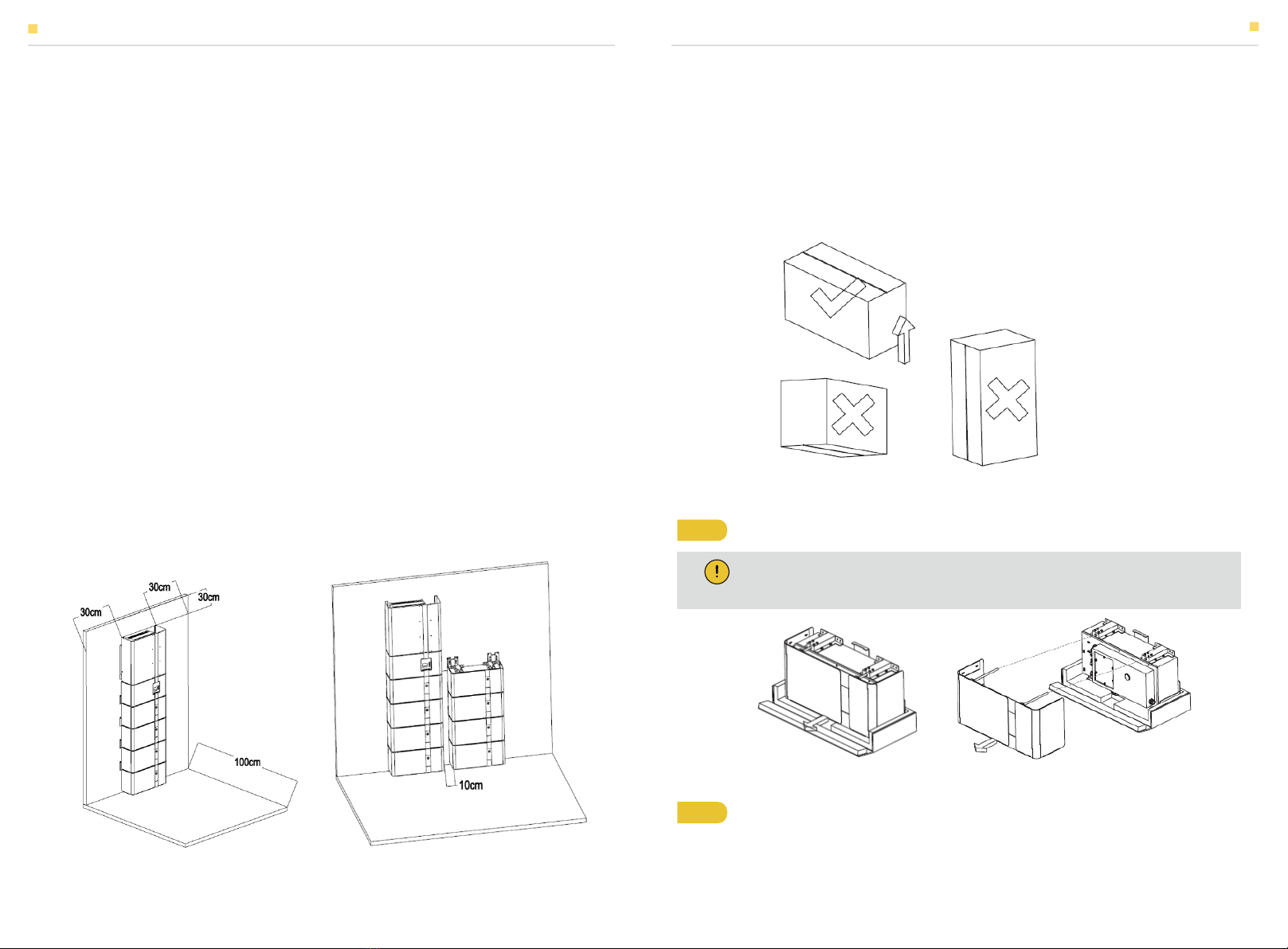
Risk of injury through lifting or dropping the system.
The inverter and battery are heavy. There is risk of injury if the inverter or battery is lifted
incorrectly or dropped during transport or when attaching to or removing from the wall.
Lifting and transporting of the inverter and battery must be carried out by more than 1
person.
WARNING
Risk of chemical burns from electrolyte or toxic gases.
During standard operation, no electrolyte shall leak from the battery pack and no toxic gases
shall form. Despite careful construction, if the Battery Pack is damaged or a fault occurs, it is
possible that electrolyte may be leaked or toxic gases formed.
Do not install the system in any environment of temperature below -10°C or over 50°C and
in which humidity is over 85%.
Do not touch the system with wet hands.
Do not put any heavy objects on top of the system.
Do not damage the system with sharp objects.
Do not install or operate the system in potentially explosive atmospheres or areas of high
humidity.
Do not mount the inverter and the battery pack in areas containing highly flammable
materials or gases.
If moisture has penetrated the system (e.g. due to a damaged enclosure), do not install or
operate the system.
Do not move the system when it is already connected with battery modules.
Secure the system to prevent tipping with restraining straps in your vehicle.
The transportation of AlphaESS Storion-SMILE-T10 must be made by the manufacturer or
an instructed personal. These instructions shall be recorded and repeated.
A certified ABC fire extinguisher with minimum capacity of 2kg must be carried along when
transporting.
It is totally prohibited to smoke in or close to the vehicle when loading and unloading.
For the exchange of a battery module, please request for new hazardous goods packaging
if needed, pack it and let it be picked up by the suppliers.
In case of contact with electrolyte, rinse the affected areas immediately with water and
consult a doctor without delay.
T10-INV box (X1)
Communication
cable (X1)
BAT-BAT
Communication
cable (X1)
Screw package:
Expansion tube (X8)
Expansion screw (X8)
Battery connector:
Positive-Negative
power line (X1)
AC terminal (X12) Cable tie (X30)
Cable bond (X1) Hexagon nuts
with flange (X2)
DC connectors:
Positive X3,
nega-tive X3
Bracket A (X1)
Bracket B (X1) AC auxiliary
power cable (X1)
3-phasig Meter (X1):
ADL3000 or ACR10R
Installation
Manual (X1)
03 04
SMILE-T10_INV