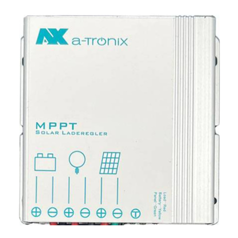
Atronix A100/20 User manual

Installation and
Operating instructions
a-TroniX MPPT solar charge controller
9887580
9887584
a-TroniX MPPT Solar Charge Controller A100/20
a-TroniX MPPT Solar Charge Controller A100/40
a-TroniX MPPT Solar Charge Controller A150/60
item number
9887582
Model
A100/20
A100/40
A150/60
page 1
02/2022
Machine Translated by Google

operation manual
INTRODUCTION
AKKU SYS Accumulator and Battery Technology North GmbH
Verbindungsweg 23 25469 Halstenbek / Hamburg GERMANY
Telephone +49 4101 | 3 76 76-0 / Fax +49 4101 | 3 76
02/2022
page 2
MPPT Solar Charge Controllers A100/20, A100/40, A150/60
The publication and copyright of this documentation remain with the company:
Machine Translated by Google

operation manual
The LCD display allows you to easily read the operating data and real-time operating
status.
All rights reserved.
We reserve the right to make design and device changes that serve to improve the
production process or the product.
The solar charge controller is protected from overheating by the built-in power
reduction function and provides automatic protection to avoid exceeding the rated
charging power and rated current.
Thank you
for purchasing our MPPT solar charge controller from the a-TroniX series.
AKKU SYS Akkumulator- und Batterietechnik Nord GmbH cannot be held
responsible for any inaccuracies or inappropriate information in these operating
instructions.
Read carefully before use!
The solar charge controller is based on advanced MPPT technology specially
developed for solar systems.
We assume no liability for errors in this manual and the resulting consequences.
Read this user manual carefully before installation.
It has a number of outstanding features, such as a combination of multiple tracking
algorithms that enable fast and accurate tracking of the maximum power point.
The information in this document is subject to change without prior notice, but there
is no obligation to keep it up to date.
It contains important regulations and notes for the use of this product and provides
technical support for the operator of the device.
MPPT Solar Charge Controllers A100/20, A100/40, A150/60
page 3
02/2022
Machine Translated by Google

operation manual
Table of Contents
5.5 Connect load
4.7 Structure and Features
7
14
20
18
19
7
13
17
11
2.2 Installation Notes
21
5.1 Installation site requirements 5.2 Fasten solar charge
controller 5.3 Connect connections
21
16
5.9 Wiring Specifications 5.10 Grounding
5.7 Connecting the PV module
4.9 RS485 port
8
15
13
7
4.1 Dimensions A100/20 4.2 Installation
positions A100/20 4.3 Dimensions A100/40 4.4
Installation positions A100/40 4.5
Dimensions A150/60 4.6 Installation positions
A150/60
19
20
5.4 Connecting accessories
17
6
13
18
21
20
15
4.10 Bluetooth communication
16
Page
8
5.8 Final Work
20
14
4.8 Temperature Sensor
2.1 Transportation and Storage
5.6 Connecting the battery
02/2022
page 4
MPPT Solar Charge Controllers A100/20, A100/40, A150/60
2. Important Safety Instructions
4. Device Description
5. Installation
3. Functions of the solar charge
controller 3.1 MPPT -
technology 3.2 MPPT - four-stage charging process
1. Symbols and abbreviations used
Machine Translated by Google

operation manual
7. Troubleshooting
8. Protections
6. Operation
9.
Maintenance 9.1 Disposal of Batteries
11. Specifications A150/60
10.Technical data A100/20, A100/40
02/2022 page 5
MPPT Solar Charge Controllers A100/20, A100/40, A150/60
27
32
25
6.11 Charging modes
23
26
6.3 LCD display 6.4 Error
display 6.5 Parameter
setting 6.6 Undervoltage protection 6.7
Reconnection voltage 6.8 Bluetooth
device password clear 6.9 Battery type 6.10
Charging voltage parameters
34
26
33
27
6.2 Key Functions
22
30
6.1 LED display
26
30
32
28
22
27
22
Machine Translated by Google

1. Symbols and abbreviations used
operation manual
ENVIRONMENT:
Danger high voltage.
Make use of the certified and professional recycling service of
our AKKU SYS team.
WARNING!
Warning when handling accumulators.
Identifies assemblies or parts that must be disposed of properly. Do not throw them
in the household waste.
QR code:
General warning of danger spots.
This symbol indicates text, hints or tips.
These are also referred to as PV systems .
In this manual, the abbreviation MPPT stands for: Maximum Power
Point Tracking.
A NOTICE:
Indicates information about recycling.
Warnings and notes are identified by the appropriate symbols (pictograms) and must be
observed:
Failure to take preventive protective measures may result in damage to the product
and/or its functions or something in its vicinity.
Accumulators are usually used as energy stores in a PV system . These are colloquially
referred to as rechargeable batteries or batteries.
Solar charge controllers are used in connection with a photovoltaic system.
For more information contact us by phone
MPPT Solar Charge Controllers A100/20, A100/40, A150/60
page 602/2022
Machine Translated by Google

2. Important Safety Instructions
operation manual
2.1 Transportation and Storage
2.2 Installation Notes
02/2022 page 7
The operating instructions must be read and understood by all persons and
specialists who work with this device and all points must be observed.
Any further use or use that goes beyond this is considered to be improper and can
lead to personal injury, damage to property and/or damage to the device.
Always store the device and the corresponding accessories in the original
packaging.
Do not try to disassemble the device. It contains no user-serviceable parts. During
installation, operation or maintenance carried out by qualified personnel, observe
the local safety instructions and the relevant laws. Otherwise personal injury or
equipment damage may occur.
The safety instructions in this manual serve as a supplement to the local safety
instructions. Our company assumes no liability for damage caused by non-
observance of the safety instructions.
Only use the solar charge controller in connection with the intended photovoltaic
systems.
Be sure to follow all warnings and instructions in this manual.
Only transport the solar charge controller in the original packaging to protect it
from bumps and knocks.
This also applies if no regular maintenance or maintenance/repairs were not carried
out by qualified specialist personnel. The device must also be set up by qualified
specialist personnel.
Before installing and adjusting the solar charge controller, be sure to turn off the
PV modules. Make sure the circuit breaker, fuse, or disconnect switches on the
battery terminals are turned off.
Keep them safe and read the following notes carefully before installing and starting
up the device.
The device must be protected from moisture and may therefore only be stored in
dry rooms.
The solar charge controller may only be used in photovoltaic systems that correspond
to the specifications of the device described in these operating instructions. No
other energy sources may be connected to it.
MPPT Solar Charge Controllers A100/20, A100/40, A150/60
Machine Translated by Google

The solar charge controller has a high efficiency of up to 98%.
Do not use metal objects near batteries.
The use of AGM, acid and gel batteries as well as lithium batteries is possible.
Always wear eye protection and avoid eye contact with battery acid. Have fresh
water ready for rinsing. If you have any symptoms, consult a doctor immediately.
When installing the solar charge controller, avoid direct sunlight, water and heat
accumulation. After
installation, check that all connections are tight.
Only use batteries that match the voltage range of the charger to store energy.
Automatic DC detection (12V / 24V / 48V).
The built-in power reduction function protects against overheating.
When handling batteries, only use insulated tools and never touch uninsulated
cable ends.
Battery life is extended by a precise temperature sensor.
Batteries can produce flammable and possibly toxic gases (oxyhydrogen).
Avoid creating any sparks near the battery.
The device has a double automatic protection to avoid exceeding the nominal
charging power and the nominal current.
The following battery charging methods are possible: MPPT, rapid charging,
equalization and trickle charging.
Batteries store a large amount of energy. Therefore, be careful not to short-circuit
the battery.
Keep children away from all electrical devices/connections etc.
An LCD display allows easy reading of the operating data.
Be extremely careful when handling batteries.
Multiple tracking algorithms enable fast and accurate tracking of maximum PV
module power.
Batteries must be installed in a well-ventilated area to allow gases to escape.
operation manual
02/2022
page 8
3. Functions of the solar charge controller
MPPT Solar Charge Controllers A100/20, A100/40, A150/60
Machine Translated by Google

Power supplied (Pmax) = solar charge controller output power (Pout)
Grid-connected solar modules can also be used as long as the open circuit voltage
of the solar system does not exceed the maximum input voltage at the worst case
(coldest) module temperature.
3.1 MPPT technology current
amplification MPPT
technology enables the PV charging current to be increased.
Assuming 100% efficiency.
It is possible to set different load modes.
For example, a 12 V battery with a nominal voltage of 12 V / 24 V / 36 V or 48 V
can be charged.
The documentation of the solar modules should contain corresponding data
depending on the temperature.
Iin x Vmp = lout x Vout
Higher PV input voltage results in lower PV input current for a given input power.
If the maximum power voltage of the solar panel (Vmp) is greater than the battery
voltage, the battery current must be proportionately greater than the solar input
current to balance the input and output power.
Monthly load data can be displayed as a summary in the form of graphics.
(Always on, dusk, evening and manual).
In fact, there are slight losses in wiring and conversion.
Another advantage of MPPT technology is the charging of batteries with PV
modules of a higher nominal voltage.
A fully automatic electronic protection function ensures increased reliability of the
solar charge controller.
The greater the difference between Vmp and battery voltage, the greater the current
gain. Current gain can be significant in systems where the solar array is rated at a
higher voltage than the battery.
The RS-485 standard protocol Modbus with RJ11 interface enables optimal
communication in various applications.
operation manual
page 9
02/2022
High-voltage strings and grid-connected modules
The device has a Bluetooth app, a Bluetooth function is available.
MPPT Solar Charge Controllers A100/20, A100/40, A150/60
Machine Translated by Google

The Vmp of a PV module decreases with increasing temperature.
In very hot weather the Vmp can be close or even below the battery voltage. Under
these conditions, the MPPT gain is very low or non-existent compared to
conventional solar charge controllers.
Because traditional solar charge controllers are not always operating at the Vmp
of the solar array, energy is wasted that could otherwise be used to charge the
battery and power grid loads.
However, in systems with modules whose rated voltage is higher than the battery
voltage, the Vmp of the solar array will always be higher than the battery voltage.
A higher PV input voltage enables a smaller cross-section of the PV wiring. This is
particularly helpful and economically interesting for systems with long cable runs
between the solar charge controller and the solar system.
The greater the difference between the battery voltage and the Vmp of the module,
the more energy is wasted.
In contrast to conventional PWM solar charge controllers (pulse width modulation),
the a-TroniX solar charge controller can reproduce the maximum output of the PV
module, so that a larger charging current can be supplied. In general, the energy
efficiency of the solar charge controller is 15% to 20% higher than that of the PWM
solar charge controller.
Conventional solar charge controllers connect the PV module directly to the battery
when charging. This requires the PV module to operate in a voltage range that is
typically below the module's Vmp value.
For example, in a 12 V system, the battery voltage can range from 10.8 V to 15.0
V, but the maximum power voltage (Vmp) values of PV modules are typically 16 V
to 17 V.
operation manual
Page 10 02/2022
Advantage over conventional solar charge controllers
MPPT Solar Charge Controllers A100/20, A100/40, A150/60
Machine Translated by Google

3.2 MPPT - Four Stage Charging Process
operation manual
Trickle Store (Float)
Fast Charge (Boost)
page 11
02/2022
When the battery is fully charged, the desired chemical reactions no longer occur in
the battery and the charging current is converted to heat and gas.
After the "boost" charging process, the solar charge controller reduces the voltage
setpoint to "trickle charging".
Once charging reaches the “boost” voltage set point, constant voltage regulation
is applied to prevent battery heating and excessive gassing. By default, fast charging
takes about 2 hours and then switches to trickle charging (“float”).
The purpose of the “Float” stage is to balance the current consumption due to self-
consumption and small loads in the entire system and to obtain full battery storage
capacity in a timely manner. Float charging allows loads to continue drawing current
from the battery. If the system loads exceed the PV charge current, the solar
charge controller will no longer be able to keep the battery at the float charge
setpoint. If the battery voltage remains below the quick recharge voltage, the
charge controller exits trickle charging and returns to charging mode.
For this reason, the charge controller sets the charging voltage to "trickle charging"
so that charging is carried out with a reduced voltage and current.
Each time the solar charge controller is switched on, the charging process changes
to the "boost" charging stage, provided no overdischarge or overvoltage is detected.
The solar charge controllers of the a-TroniX series have a 4-stage battery charging
algorithm for fast, efficient and safe battery charging.
This process lowers the temperature of the battery and prevents gas formation.
MPPT charging
In this phase, the battery voltage has
not yet reached the "boost" charging
voltage and 100% of the available PV
energy is used to charge the battery.
At the same time, the battery is slightly charged.
MPPT Solar Charge Controllers A100/20, A100/40, A150/60
Machine Translated by Google

Equalization (Equilization)
operation manual
page 12 02/2022
There is a risk of explosion!
Explosive gases may be generated when equalizing a fully charged battery. Good
ventilation of the battery is therefore necessary.
By default, this takes about 2 hours.
Equalizing charge and quick charge are not performed continuously in each full charge to avoid
over-voltage and/or overheating of the battery.
Certain battery types benefit from periodic equalization charging.
WARNING:
By balancing the charge, the battery voltage increases.
This is higher than the standard complementary voltage, which converts the battery electrolyte
into gas. When the battery is detected to be overcharged, the solar charge controller will
automatically switch the battery to equalization charge.
MPPT Solar Charge Controllers A100/20, A100/40, A150/60
Machine Translated by Google

4. Device description
4.1 Dimensions A100/20
operation manual
Dimensions: mm
02/2022 page 13
4.2 The installation position A100/20
MPPT Solar Charge Controllers A100/20, A100/40, A150/60
Machine Translated by Google

4.3 Dimensions A100/40
4.4 Installation
positions
A100/40
operation manual
02/2022
page 14
Dimensions: mm
MPPT Solar Charge Controllers A100/20, A100/40, A150/60
Machine Translated by Google

4.5 Dimensions A150/60
4.6 Installation
positions
A150/60
operation manual
page 15
02/2022
Dimensions: mm
MPPT Solar Charge Controllers A100/20, A100/40, A150/60
Machine Translated by Google

4.7 Structure and Features
4.8Temperature sensor
operation manual
page 16 02/2022
9 solar panel connector
for collecting temperature information
In order for the solar charge controller to be able to charge the battery precisely, the battery temperature
data is recorded via a temperature sensor for temperature compensation.
5 temperature sensor
for connecting monitoring devices
An 80 mm long temperature sensor cable is included with the charger. Larger cable lengths must be
ordered separately.
6 RJ11 interface
The sensor is connected via interface 5.
2 plastic housings to
protect internal components
3 LED + LCD display to
show settings and working status
for connecting consumers
NOTE: If
the external temperature sensor is damaged or not connected, the solar charge controller will
use the internal temperature information by default.
1 heatsink for
heat dissipation
7 load connection
for connecting the solar module
for setting and displaying the
operating parameters
8 Battery connector to
connect the battery
4 buttons Menu + OK
MPPT Solar Charge Controllers A100/20, A100/40, A150/60
Machine Translated by Google

4.9 RS485 port
4.10 Bluetooth communication
operation manual
page 17
02/2022
The RS485 interface of the solar charge controller is not galvanically isolated and
must therefore not be grounded. Do not short unused pins (note NC).
The Bluetooth communication has the following properties: 1.
Android & iOS app is supported.
4. Uses Bluetooth 4.2 e BLE technology.
A NOTICE:
2. Realizes the solar charge controller wireless monitoring function.
There are two options:
For operation details, refer to the Bluetooth app instructions.
The solar charge controller is equipped with an RS485 connection and an RJ25 6P2C plug. The
contacts are assigned as follows:
3. Uses high-performance, ultra-low current Bluetooth chip
1. Bluetooth intern
WARNING:
consumption.
2. Bluetooth external (Cyber-BT), via connector type RJ25 6P2C.
MPPT Solar Charge Controllers A100/20, A100/40, A150/60
Machine Translated by Google

5. Installation
operation manual
Only install the solar charge controller in places that are protected from direct sunlight or other
heat sources, dirt and moisture.
A minimum distance of 15 cm under and around the device should be kept free for unhindered
air circulation.
Attach it so that the cable holes are facing down.
Fix it upright on the wall. Make sure that this is a non-combustible wall material.
If possible, mount the solar charge controller close to the battery.
page 18 02/2022
5.1 Installation site requirements
MPPT Solar Charge Controllers A100/20, A100/40, A150/60
Machine Translated by Google

5.2 Fasten the solar charge controller
5.3 Connecting connections
operation manual
02/2022 page 19
Explosion Hazard: There is a risk of fire or explosion if the battery terminals or cables
are shorted.
WARNING:
The PV module can exhibit open circuit voltages of more than 100 V when exposed
to sunlight. Watch out for this hazard.
First, drill the 4 mounting holes according to the installation positions in “5. Device description”
on the wall.
The inside temperature is automatically displayed if no solar charge controller is
connected. An inverter must always be mounted directly on the battery, never on the
load terminals of the solar charge controller.
WARNING:
DANGER:
Then attach the solar charge controller to the pre-drilled holes.
MPPT Solar Charge Controllers A100/20, A100/40, A150/60
Machine Translated by Google

5.6 Connecting the battery
5.7 Connecting the PV module
5.5 Connect load
5.4 Connecting accessories
operation manual
02/2022
page 20
Voltages are noticeable when the controller is set to a lithium battery.
With a nominal voltage of 12 VDC, the battery voltage should be in the range of 5.0
to 15.5 VDC.
When connecting the PV module, make sure that it is protected from direct sunlight.
Make sure that the PV module does not exceed the maximum permissible input
current of the solar charge controller (see section "Technical data").
Connect the load cable to the right pair of terminals on the solar charge controller with
the correct polarity.
If the polarity is set correctly, these are displayed on the LCD of the solar charge
controller.
With a nominal voltage of 24 V DC, the battery voltage should be in the range of
20.0 to 31.0 V DC.
To avoid tension in the cables/wires, first connect them to the load before connecting
them to the solar charge controller.
1. Connect the temperature sensor cable.
With a nominal voltage of 36 VDC, the battery voltage should be in the range of 31.0
to 42.0 VDC.
Connect the solar module connection cable to the solar charge controller with the
correct polarity of the left pair of clamps (solar module symbol). Pay attention to the
requirements of the mounting location.
2. Then connect the cable for the RS485 communication.
With a nominal voltage of 48 VDC, the battery voltage should be in the range of 40.0
to 62.0 VDC.
Connect the battery to the middle pair of terminals on the solar charge controller with
correct polarity. Never reverse the positive (+) and negative (-) poles.
MPPT Solar Charge Controllers A100/20, A100/40, A150/60
Machine Translated by Google
This manual suits for next models
5
Table of contents
Other Atronix Controllers manuals
