manuals.online logo
Brands
  1. Home
  2. •
  3. Brands
  4. •
  5. Leroy-Somer
  6. •
  7. Controllers
  8. •
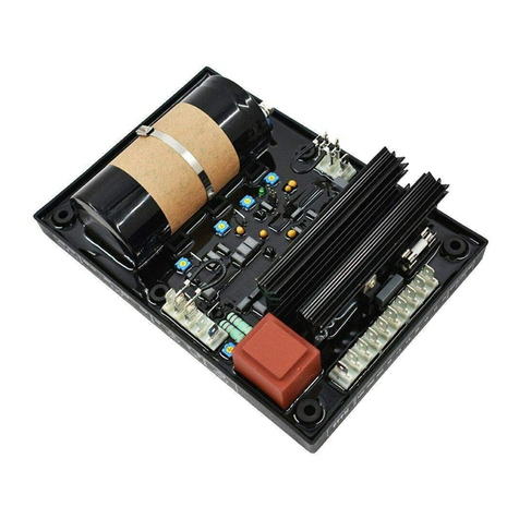
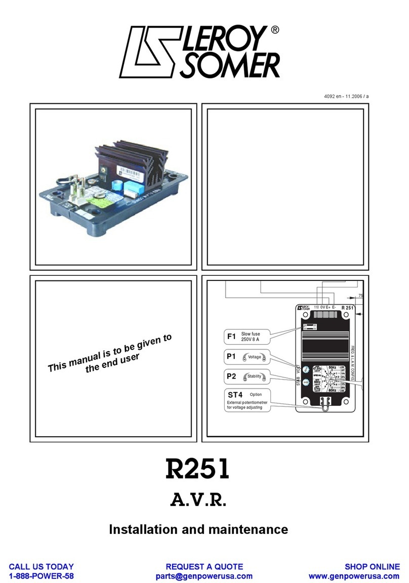
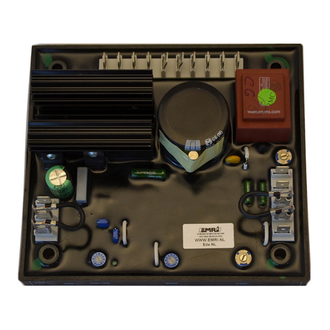
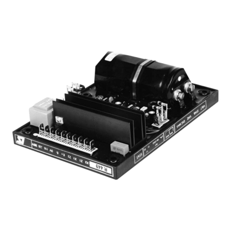
  9. Leroy-Somer R630 Instruction Manual

Leroy-Somer R630 Instruction Manual

AUTOMATIC VOLTAGE
REGULATOR
R630
Installation and maintenance
Réf. 2352 - 4.33 / a - 6.96
GS
3Ø
Power
VT
parallel
running C
T
2 measure
VT 2 or 3 measure
VT
Out of supply
o
r
Optional
Booster
board
De-ener
g
izin
g
A V
R
(Control
)
(Power)
3 booste
r
CT
Mains measur
e
Out of supply
Comman
d
inputs Potentiomete
r
inputs
Rotatin
g
diode
failure
detector
(
OPTION
)
Fault outpu Alarm outpu
t
o
r
TABLE OF CONTENT
AVR CONSTITUTION ............................................................................................................................ 3
GENERAL DESCRIPTION : NT1950000 /a ........................................................................................... 4
CARDS DESCRIPTION : NT1950xxx .................................................................................................. 12
START-UP : NT1959000 /a .................................................................................................................. 45
2
AVR
Model R630
NOTE
THE ELECTRICAL CONNECTION DIAGRAM ARE ONLY GIVEN
AS AN INDICATION. PLEASE REFER TO THE SPECIFIC DIAGRAMS
OF YOUR ALTERNATOR.
WARNING
TO PREVENT PERSONNAL INJURY OR EQUIPMENT DAMAGE,
ONLY QUALIFIED TECHNICIANS/OPERATORS SHOULD
INSTALL AND OPERATE THIS DEVICE.
CAUTION
MEGGERS AND HIGH POTENTIAL TEST EQUIPMENT MUST NOT BE
USED. INCORRECT USED OF SUCH EQUIPMENT COULD
DAMAGE THE SEMICONDUCTORS CONTAINED IN THE AVR.
3
Constitutive
elements
AVR
Model R630
DESIGNATION N°printed N°complete N°instruction REMARKS
circuit board card manual
Wired empty rack C51950250 NT1950000/c-02/95 SHUNT (+booster)
Wired empty rack C51950251 NT1950001/b-10/94 PMG
Complete Generator I/O board C51950200 NT1950010/b-10/94 100 / 120V - 50 / 60Hz
Complete Generator I/O board C51950202 NT1950010/b-10/94 400 / 450V - 50 / 60Hz
3F Complete Mains I/O board C51950220 NT1950020/b-10/94 100 / 120V - 50 / 60Hz
3F Complete Mains I/O board C51950222 NT1950020/b-10/94 400 / 450V - 50 / 60Hz
2F Complete Mains I/O board C51950210
1F Complete Interface board C51950215
Rack supply CP1950040 C51950041 NT1950040/a-11/92
Sensing CP1950050 C51950051 NT1950050/a-11/92
PID, limitation CP1950060 C51950061 NT1950060/a-11/92
Driver CP1950070 C51950071 NT1950070/b-11/93
CosØ, KVAR CP1950080 C51950081 NT1950080/b-10/94
Limit Istator CP1950090 C51950091 NT1950090/a-11/92
Manual mode 1 CP1950100 C51950101 NT1950100/a-02/93
Digital U / P.F potentiometer CP1950110 C51950111 NT1950110/a-01/94
Digital Ified pot and Follower CP1950115 C51950141 NT1950115/a-01/94
Mains P.F régulation CP1950120 C51950121 NT1950120/a-04/94
Rotating diode fault detector CP1950130 C51950131 NT1950130/a-06/96 Available June 1996
= Neccessary
= Optionals
IMPORTANT : The informations given by this sheet must be used to order spare parts. Take care of it.
1 - APPLICATION
- The AVR model R600 can be used with brusless self-
excited type generators, "SHUNT", "SHUNT with BOOS-
TER" or "SHUNT with PMG" excitation. In case of
"SHUNT with BOOSTER the booster current is totally
monitored by the AVR.
- The AVR is able to ensure, depending of its constitu-
tion, solo operation, parallel operation between equiva-
lent generators or parallel operation with the mains with
cosØ or KVAR regulation.
2 - DESCRIPTION
- The AVR model R631 is composed of electronic cards
wich are included in a rack 19" .
- Except the necessary "Generator I/O", the optional
"mains I/O" located on the left of the rack and the "driver"
card located on the right, all the other cards can be plug-
ged anywhere in the rack. Future optional cards could be
added without any internal wiring modification.
- The rear flat cable (BUS 64 points) is given more long
as it can be connected to an optional interface terminal
block wich gives all the internal test points or in the
future the possibility to connect another rack if the cards
number will become too important.
3 - INTERCONNECTIONS
- External interconnections are located on the top of the
rack in form of two terminal blocks:
- A power / voltage terminal block (19 terminals, one with
a fuse )
- A command / control terminal block (41 terminals)
- A conventional wiring connect this terminal blocks to
the power block fitted on a heatsink and also to the
"generator I/O" and "mains I/O" to give an interface with
the flat cable BUS 64 points.
- In the same manner a 8 points connector connects
directly the driver card to the power block.
4 - OPTIONAL CARDS
- CosØ / KVAR regulation (2F)
- Voltage equalization with the mains (3F)
- Voltage and P.F digital potantiometers
- Manual operation
- Ifield digital potentiometer with follower
- Istator limitation
- Mains P.F or KVAR regulation from 4-20mA sensor
- Rotating diodes fault monitor
5 - SPECIFICATIONS
- Sensing voltage :
• 100/110Vac 50Hz
• 120/130Vac 60Hz
• 380/420Vac 50Hz
• 430/450Vac 60Hz
- Power supply :
• Depend of generator(Adaptation by transformer).
Maximum 180Vac 50/60Hz
- Field output :
• 12 Amperes nominal, 24Amp maximum during 10s on
6Ωminimum
- Accuracy :
• +/-1% of the means of the three phases on linear load
and without droop
- Voltage setting range :
• +/-10% of the nominal voltage by means of external
optionnal potentiometer .
- Droop setting range :
• - 7% of the nominal voltage at cosØ =0
- Under-frequency protection :
• Adjustable threshold and slope from V/Hz to 2V/Hz
- Field ceiling :
• 110% of If nominal permanently, unlocked in case of
voltage decrease
- Protection :
• Heatsink overheating, exciter short-circuit
- Alarm output :
• Heatsink overheating, too much ceiling unlocked time
- Environnement :
• Maximum ambiant temperature -10°C to +50°C
• Fitting in control panel without excessive vibrations
6 - SCHEMATICS AND DRAWINGS
Following schematics give all the usual informations on
the interconnexions between the terminal block, the I/O
connectors and the power block.
4
General
description
AVR
Model R630
NT1950000/c-02/95 f:1/8
5
General
description
AVR
Model R630
NT1950000/c-02/95 f:2/8
MIMIC DIAGRAM EXCITATION - REGULATION
GS
3Ø
Power
VT
parallel
running CT
2 measure
VT 2 or 3 measure
VT
Out of supply
or
Optional
Booster
board
De-energizing
A V R
(C
ontrol
)
(
Power
)
3 booster
CT
Mains measure
Out of supply
Comman
d
inputs Potentiometer
inputs
Rotating
diode
failure
detector
(OPTION)
Fault outpu
t
Alarm outpu
t
or
TERMINAL BOX
COMMAND / CONTROL TERMINAL BLOCK
VOLTAGE POT
COSØ POT
COSØ POT
COSØ POT
Measure If
Measure If
2122 23 24 25 26 27 28
COSØ CMD
KVAR POT
KVAR POT
KVAR POT
29 30 31 32
U/U CMD
ALARM
U/U CMD
ALARM
ALARM
+ 24Vdc ext
- 24Vdc ext
COSØ CMD
33 34 35 36 37 38 39 40
+ CMD U / P.F
41 42 43 44
Auto / Manu
Info Auto / Manu
Auto / Manu
Info Auto / Manu
45 46 47 48 49 50 51 52
-Iexc CMD
+Iexc CMD
Commun
53
SHIELDS
20
VOLTAGE / POWER TERMINAL BLOCK
U MAINS
V MAINS
W MAINS
// CT
123
U MACHINE
V MACHINE
W MACHINE
+ Field
- Field
4 5 6 7 8 9 10 11 12
// CT
13 14 15 16 17 18 19
Auxiliary voltage
5354 55 56 5357 58 59 5360
Ifield Pot
Manual pot
COSØ / KVAR CMD
Réserve
Réserve
Réserve
Réserve
Réserve
Réserve
Réserve
Power supply
Power supply(fuse)
VOLTAGE POT
VOLTAGE POT
VOLTAGE CMD
+ Field flash
+ Booster
- Booster
Auxiliary voltage
- CMD U / P.F
6
General
description
AVR
Model R630
NT1950000/c-02/95 f:3/8
TERM N°VOLTAGE / POWER TERMINAL BLOCK 0F 1F 2F 3F
1Phase 1 (U) machine (measure) NNNN
2Phase 2 (V) machine (measure) NNNN
3Phase 3 (W) machine (measure) NNNN
4+ fiel flashing or pre-excitation input (optional) OOOO
5+ field output NNNN
6- field output NNNN
7+ booster input OOOO
8- booster input OOOO
9Paralleling CT phase 2 (V) S1 N N N
10 Paralleling CT phase 2 (V) S2 N N N
11 Not connected
12 Phase 1 (U) mains (measure) N
13 Phase 2 (V) mains (measure) N
14 Phase 3 (W) mains (measure) N
15 Not connected
16 Auxiliairy voltage input NNNN
17 Auxiliairy voltage input NNNN
18 Power supply input NNNN
19 Power supply input (fused) NNNN
COMMAND / CONTROL TERMINAL BLOCK
20,20,20 Potentiometer shield (3 terminals) OOOO
21 External voltage potentiometer maximum CW) OOOO
22 External voltage potentiometer (10KΩ-2W) (cursor) OOOO
23 External voltage potentiometer ( minimum CCW) OOOO
24 External voltage input (10Vdc, 0V to terminal 20) OOOO
25 Fied current measurement output (+Vdc) OOOO
26 Fied current measurement output (0V) OOOO
27 External cosØ potentiometer maximum CW) O O
28 External cosØ potentiometer (10KΩ-2W) (cursor) O O
29 External cosØ potentiometer ( minimum CCW) O O
30 External KVAR potentiometer maximum CW) O O
31 External KVAR potentiometer (10KΩ-2W) (cursor) O O
32 External KVAR potentiometer ( minimum CCW) O O
33 cosØ regulation command input N N
34 cosØ regulation command input N N
35 Voltage equalization command input N
36 Voltage equalization command input N
37 Overheating or ceiling unlocked time alarm (common) OOOO
38 Overheating or ceiling unlocked time alarm output (NC) OOOO
39 Overheating or ceiling unlocked time alarm output (NO) OOOO
40 External +24Vdc supply input ( relay locking) OOOO
41 External 24Vdc supply input ( relay locking) common OOOO
42 Upper command voltage and P.F OOOO
43 Lower command voltage and P.F OOOO
44 Common OOOO
45 Upper command Ifield (manu) OOOO
46 Lower command Ifield (manu) OOOO
47 "AUTO / MANU" command input (Open = "AUTO") OOOO
48 "AUTO / MANU" command input (Open = "AUTO") OOOO
49 "AUTO / MANU" image output OOOO
50 "AUTO / MANU" image output OOOO
51 Ifield direct manual setting potentiometer OOOO
52 Manual mode 1 card Ifield setting potentiometer (10KΩ) OOOO
53 CosØ / KVAR selection command input (/ terminal 48) O O
54 Reserve
55 Reserve
56 Reserve
57 Reserve
O = Optional O = Optional
N = Neccessary N = Neccessary
Nothin
g
= Not applicable Nothin
g
= Not applicable
7
General
description
AVR
Model R630
NT1950000/c-02/95 f:4/8
18 19
RBD
1µF
400V
2x1000µF
350V in //
or
2200µF 400V
56
7 8
9
c
10c
4
47Ω50W
+15 -15
M
+
P414
6
7
2
3
8
5
1
4
6
8
7
2
3
69
70
7
4
5
8
6
19
18
5
55
60
8
8
8
7
1
8
RC
60
8
5
63
64
B
B
1
4
6
8
7
2
3
5
LEM
Card
C1
E1
G1
C
2
E2
G2
7
8
OPTION
65
Connector LMI 8pt
s
Power supply
Power supply
Free
wheeling
diode
OVDC
Power supply
+VDC
Power supply
HALL
sensor
Booster
monitor
ON HEATSIN
K
+ Field
- Field
+ Booste
r
- Booster
To 32 points connecto
r
P4 on "MAINS I / O"
POWER TERMINALS
+ Field flashing
POWER BLOCK REF: C5 195 210
0
Power wiring
Thermocontact
To LMI 8 points connector
on driver card
U MAINS
W MAINS
12 13 14
U/U CMD
U/U CMD
3536
123
U MACHINE
V MACHINE
W MACHINE
4
// C
T
910 11
// C
T
16 17
Auxiliary supply
+ 24Vdc ex
t
- 24Vdc ex
t
40
+U CM
D
-U CMD
41424344
Auto / Manu
Info Auto / Man
Auto / Manu
Info Auto / Man
45 46474849 50 51 52
-If CMD
+If CMD
Commun
53
15c
13c
11c
16c
10c
1a
1c
VOLTAGE PO
T
212223 24
Measure I
f
25
Measure I
f
26
COSØ POT
27
COSØ POT
28
COSØ POT
29
KVAR POT
30
KVAR POT
31
KVAR POT
32
COSØ CM
D
33
COSØ CM
D
34
SHIELDS
20
10c
7a
3c
6c
3a
4a
10c
5c
8a
6a
12a
4c
5a
14a
2c
2c
14c
13a
2c
12c
8c
15a
2c
9c
11a
15c
11c
7c
2c 4c
2a
16a
P4 MAINS I/O
J1 bac
Generator
I/O CONTROL TERMINALS
Connectors wiring 32pt
s
POWER TERMINAL
S
V MAIN
S
2c
1a
3a
3c
Ifield PO
T
COSØ / KVAR
37 38
7c
9a
39
10a
ALARM
ALARM
ALARM
5455
RESERVE
RESERVE
5657
RESERVE
RESERVE
5859
RESERVE
RESERVE
60
RESERVE9a
2a
7a
8a
6a
4a
5a
Manual PO
T
CONTROL TERMINALS
POWER TERMINALS
CONTROL TERMINALS
VOLTAGE PO
T
VOLTAGE PO
T
VOLTAGE CMD
Auxiliary supply
61
RESERVE5c
- The following tables give interconnections between
each card and the 64 points flat cable.
- Grey cases give signals origine.
- Other cases where they go.
- On the left we have two numbers :
• First the connector numering
• Second test block terminal number
- On the right we have a recapitulative of all the informa-
tions wich can be found on the test terminal block.
8
General
description
AVR
Model R630
NT1950000/c-02/95 f:5/8
R630 POWER BLOCK SHUNT (+ BOOSTER)
Connector
LMI 8
p
oint
s
6
4
60
65
8
1
8
6
3
1
9
5
8
5
8
7
6
0
5
8
1
8
6
7
6
7
300m
m
132mm
120mm
2200µF 400
V
LEM board 74mm x 78mm
1µF
400Vac
9c 10c
To MAINS I / O P4
7
56 78
ARCOL 47Ω50
W
4
5
8
6
7
4
19
18
19
Power suppl
y
Power suppl
y
+ Booster
- Booster
+ Field flashing
+
Fi
e
ld
- Field
18
Booste
r
IGBT Main
IGBT Rectifier
bridge
LEM
9
General
description
AVR
Model R630
NT1950000/c-02/95 f:6/8
PIN PIN Gen I/O Mains I/O Supply Sensing PID, limit CosØ,KVAR Pot digital U Pot digital Iexc Manu mode Driver test output
1c 1 +Vcc +Vcc +Vcc +Vcc +Vcc +Vcc +Vcc +Vcc +Vcc +Vcc +Vcc
1a 2 +Vcc +Vcc +Vcc +Vcc +Vcc +Vcc +Vcc +Vcc +Vcc +Vcc +Vcc
2c 3 +Vdc alim +Vdc alim +Vdc alim
2a 4+Vdc alim +Vdc alim +Vdc alim
3c 5 -Vdc alim -Vdc alim -Vdc alim
3a 6-Vdc alim -Vdc alim -Vdc alim
4c 7 Vac puiss 1 Vac puiss 1 Vac puiss 1 Vac puiss 1
4a 8Vac puiss 2 Vac puiss 2 Vac puiss 2
5c 9 GND GND GND GND GND GND GND GND GND GND GND
5a 10 Vac-dr1 Vac-dr1
6c 11 Vac-dr2 Vac-dr2
6a 12 Vac-dr3 Vac-dr3
7c 13 GND GND GND GND GND GND GND GND GND GND GND
7a 14 Vac-dm1 Vac-dm1 Vac-dm1
8c 15 Vac-dm2 Vac-dm2 Vac-dm2 Vac-dm2
8a 16 Vac-dm3 Vac-dm3 Vac-dm3
9c 17 V-10% V-10% V-10% V-10%
9a 18 TI// TI// TI// TI//
10c 19 Déphasage Déphasage
10a 20 Ures Ures Ures
11c 21 Um Um Um
11a 22 Uref Uref Uref Uref
12c 23 Correct PID Correct PID Correct PID
12a 24 IsinØ IsinØ
13c 25 Uregl Uregl Uregl
13a 26 Statisme D Statisme D Statisme D
14c 27 cosØ, KVAR cosØ, KVAR cosØ,KVAR
14a 28 IcosØ IcosØ IcosØ
15c 29 Sauto Sauto Sauto Sauto Sauto
15a 30 Smanu Smanu Smanu Smanu
16c 31 cde Iexc cde Iexc cde Iexc cde Iexc cde Iexc
16a 32 GND GND GND GND GND GND GND GND GND GND GND
10
General
description
AVR
Model R630
NT1950000/c-02/95 f:7/8
PIN PIN Gen I/O Mains I/O Supply Sensing PID, limit CosØ, KVAR Pot dig U Pot dig Iex Manu mode Driver puiss test output
17c 33 GND GND GND GND GND GND GND GND GND GND GND
17a 34 Mes Iexc Mes Iexc Mes Iexc
18c 35 synchro Perte synchro Perte synchro
18a 36 I limit I limit I limit
19c 37 GND GND GND GND GND GND GND GND GND GND GND
19a 38 Fin rampe Fin rampe Fin rampe Fin rampe
20c 39 U cosØ U cosØ U cosØ U cosØ
20a 40 P.F/KVAR P.F/KVAR P.F/KVAR P.F/KVAR
21c 41 U KVAR U KVAR U KVAR U KVAR
21a 42 Pot tension Pot tension Pot tension
22c 43 U tension U tension U tension
22a 44 +Iexc +Iexc +Iexc
23c 45 -Iexc -Iexc -Iexc
23a 46 +Uauto +Uauto +Uauto
24c 47 -Uauto -Uauto -Uauto
24a 48 Cde reg cosØ Cde reg cosØ Cde reg cosØ
25c 49 Cde U=U Cde U=U Cde U=U
25a 50 cde auto/manu Cde A/M cde auto/manu cde auto/manu cde auto/manu
26c 51 Défaut T°CDéfaut T°CDéfaut T°C
26a 52 reserve
27c 53 Cde U Cde U Cde U
27a 54 reserve
28c 55 reserve
28a 56 reserve
29c 57 reserve
29a 58 reserve
30c 59 Max pot Max pot Iexc
30a 60 Max pot Max pot U/P.F
31c 61 reserve
31a 62 Alarm Alarm Alarm
32c 63 -Vcc -Vcc -Vcc -Vcc -Vcc -Vcc -Vcc -Vcc -Vcc -Vcc -Vcc
32a 64 -Vcc -Vcc -Vcc -Vcc -Vcc -Vcc -Vcc -Vcc -Vcc -Vcc -Vcc
11
General
description
AVR
Model R630
NT1950000/c-02/95 f:8/8
1
19
20
60
Bloc puissance
Power components
Bornier
Terminal block
Bornier
Terminal block
Radiateur
Heatsink
123
45
678910 11 12
40
314
370
436
Bac
alternateur
alternator
I / O
Bac
réseau
mains
I / O
option
Aliment.
supply
Détect.
sensing
KVAR
cos Ø
option
PID et
limite
PID and
limit
Limite
I stator
I stator
limit
option
Driver
puiss.
power
control
466,7
482,6
=
=
37,7 57,1 37,7
132,5
Bornier
Terminal block
Bornier
Terminal block
165
356
9,5
15
Date : 30/12/92
Verif : L . D
Des. : P . B
ENCOMBREMENT REGULATEUR de TENSION
AUTO. VOLTAGE REGUL.GENERAL ARRANGEMENT
--------------------------
SHUNT - - - Serie : R 600 N °EN 182 2511
45005 ORLEANS
FRANCE
A C E O
Ateliers de Constructions Electriques
d'Orléans
:R630
1 - FUNCTIONAL
- This unit is mainly an interface between external signals
and low power electronics.
- It is composed by :
• The adaptation three phases transformer between input
voltage and measurement circuits.
• The burden resistor of parallel CT.
• The adaptation transformer between input voltage and
low power electronic supplies.
• The interface input relays between command / control
terminals and internal circuits.
• The interface between 64pts BUS and the analogic in-
put / output terminals
2 - ADJUSTMENTS
- Setting of the auxiliary input voltage (terminals 16,17) :
(110 or 220Vac) by jumpers.
3 - INPUT / OUTPUT
See following table
12
Generator
I / O
AVR
Model R630
NT1950010/b-10/94 f:1/3
INPUT Connector Type Interface Connector Connector
TERMINAL 32 PTS I / O 26 PTS BUS 64 PTS
1 15c measure transfo 3Ø TP4 4 7a
1 15c alim transfo TP2
2 13c measure transfo 3Ø TP4 2 8c
2 13c alim transfo TP1/2
3 11c measure transfo 3Ø TP4 3 8a
3 11c alim transfo TP1
9 16c measure resistance RTI 5 9a
10 10c measure GND 1 7c
16 1a alim transfo TP3 4c
17 1c alim transfo TP3 4a
20 10c shield GND 1 7c
21 7a signal resistance 13 11a
22 3c signal direct 14 21a
23 6c signal resistance 15 7c
24 3a signal direct 16 22c
25 4a signal direct 21 17a
26 10c signal GND 1 7c
27 5c signal resistance 6 1c
28 8a signal direct 17 20c
29 6a signal resistance 23 32a
30 12a signal resistance 6 1c
31 4c signal direct 19 21c
32 5a signal resistance 23 32a
33 14a cmd input relay 8 24a
34 2c cmd input relay
37 7c cmd output relay 25 31a
38 9a cmd output relay 25 31a
39 10a cmd output relay 25 31a
40 2a ext supply relay
41 2c ext supply relay
42 14c cmd input relay 9 23a
43 13a cmd input relay 10 24c
44 2c common relay
45 12c cmd input relay 11 22a
46 8c cmd input relay 12 23c
47 15a cmd input relay 7 25a
48 2c cmd input relay
49 9c cmd output relay 12 23c
50 11a cmd output relay
13
Generator
I / O
AVR
Model R630
NT1950010/b-10/94 f:2/3
Pot U
Pot U
20
c
21
c
31
a
17
a
cosØ po
t
cosØ pot
KVAR pot
KVAR pot
cmd by U 22
c
-Vcc 32
a
Info Alar
m
Info Alar
m
Info Alar
m
cosØ pot
KVAR pot
Measure I
f
11
a
7
c
21
a
Pot U
U alt
V alt
W alt
// CT
7
a
8
c
8
a
9
a
7
c
Alim auxi
l
16a,17
c
2c,2a
3c,3a
4
c
4
a
R1
// CT - GN
D
cosØ cm
d
Auto/Man
+U
- U
+I exc
-I exc
-24Vd
c
25
a
24
a
23
a
24
c
22
a
23
c
+24Vdc U/
U
Info Man
Info Man
+Vcc 1
c
Wiring by connector HE10 26pts and flat cable
Wiring by connector LMI 10pts and normal cables
+Vcc
+Vcc
+24Vdc ex
TP4
TP2
TP1
TP3
15c
13c
11c
16c
10c
1a
1c
2a
2c
15a
16a
14c
14a
12c
13a
8c
11a
9c
7a
3c
3a
6c
5c
8a
6a
12a
4c
5a
7c
9a
10a
4a 21
25
19
23
17
15
16
13
14
9
12
10
11
7
8
6
5
1
3
2
4
2
1
7
8
3
6
4
5
9
10
Connector
HE10 26Pts
Male Connector
DIN41612 32Pts
48 47
34 33
44 42
44 43
44 45
44 46
40
17
16
10
9
3
2
1
30
32
31
29
28
27
22
21
24
23
39
38
37
25
49
50
}
Terminal N°
}
}
Terminal N°
CR1
C1 C2
Q1
K1
K2
K3
K4
K5
K6
K7
CR3
CR4
CR5
CR6
CR7
CR8
CR2 R14
R17 DS1
R13
R18 DS2
R12
DS3
R11
DS4
R10
DS5
R9
DS6
R8
R7
R6
R5
R4
R3
K8 CR9 R15
DS7
R2
R16
CR21
to 24
CR5 to 10
CR11 to 16
CR17 to 20
PT
3
PT
2
PT1
Alim auxil 220V
110V
04/10/9
4
Male Connector
DIN41612 64Pts
04/10/94
14
Generator
I / O
AVR
Model R630
NT1950010/b-10/94 f:3/3
TP
4
relai LE
D
R TI//
Connect
TP3
28V
A
TP1
15V
A
Connect
TP3
28V
A
TP2
15V
A
781
2
Capa
TP1 TP
2
TP
4
TP
1
TP2
TP3
28V
A
TP
4
ALTERNATEUR E / S
GENERATOR E / S
PT3
PT2
PT1
-U auto
+U auto
Cde cosØ
auto/manu
Alarm
-I exc
+I exc
1 - FUNCTIONAL
- This card, from not regulated symetrical voltage, genera-
tes +15Vdc and -15Vdc voltages with 0V common to both
named +Vcc for +15V and Vdd for -15V in the following.
- The non regulated voltages are first filtered (C01, C02),
pre-regulated to 20dc with ballast stages Q01 et Q02
and finally decreased to15V by means of RG01 et RG02
regulators.
- Its permanent current capability is 0,5 Amp on both
polarity.
2 - ADJUSTMENTS
None
3 - INPUTS / OUTPUTS
- 2a, 2c : Input +30Vdc not regulated
- 3a,3c : Input -30Vdc not regulated
- 1a,1c : Output +15Vdc regulated (Vcc)
- 32a,32c: Output -15Vdc regulated (Vdd)
- 16a,17c: Common electronic ground
15
Supply
card
AVR
Model R630
NT1950040/a-11/92 f:1/2
MIMIC DIAGRAM OF ELECTRONIC SUPPLY CARD
+V not
regulated
2a,2c Regulator
+15Vdc
LED
+15V
32c,32
a
1c,1a
16a,17c
-Vdd
+Vcc
0V
Pre-regul
Filter
3a,3c Regulator
-15Vdc
LED
-15V
0v 16a,17c
-V not
regulated Pre-regul
Filter
16
Supply
card
AVR
Model R630
NT1950040/a-11/92 f:2/2
ALIMENTATION
SUPPLY
PT3
PT2
PT1
-15V
+15V
C05
C01 R01
CR01
CR03
R0
2
CR02
C02
Q01
Q02
7
915
7
815
RG01
RG02
CR04 C06
3,4
32,33
5,6
6
3,64
1,2
C03
C04
DS2
DS1
R03
R04
TP1
TP3
TP2
330Ω
BZX85C20
1000µF 40V
1000µF 40V
330ΩBZX85C20
0,33µF 63v
0,33µF 63v
3,3KΩ
3,3KΩ
0
,33µF 63v
0
,33µF 63v
1N4007
1N4007
TIP41
TIP42
1 - FUNCTIONAL
- This card elaborates from the three phases voltage
image of the generator given by the "ALTERNATOR I/O" :
- A rectified, calibrated, filtered voltage Vm proportional
to the stator voltage of the generator. Vm could be affect-
ed by droop depending of adjustment.
- A voltage function of the generator frequency, a part of
which gives the reference set point named Vref.
- Vref is a constant above the underfrequency threshold
set point (signaled by LED) and decreases below this
threshold following a function depending of the position
of the strap CV1:
• In fixed V/Hz mode
• In adjustable kVolt / Hz (see curve below)
2 - ADJUSTMENTS
- P1 : Reactive droop adjust for parallel operation bet-
ween equivalent machine.
- P2 : Vm adjust for nominal voltage. (9Vdc at Un)
- P3 : Underfrequency threshold adjust (normally Fn -
5%) signaled by LED.
- P4 : Underfrequency slope adjust ( k ) in kVolt / Hz mode
(1≤k ≤2)
- P5 : Voltage set point Vref for the nominal voltage
(10Vdc at Un and Fn)
3 - INPUTS / OUTPUTS
- 7a, 8a, 8c : Voltage inputs image of the generator (3 x
21Vac between each and the GND)
- 9a : Current input image of the generator stator
current (1Vac pour In)
- 1a,1c : +15Vdc regulated (Vcc)
- 32a,32c : -15Vdc regulated (Vdd)
- 16a,17c : Common ground (GND or 0V)
- 11c : Voltage output image of the generator (Vm)
10Vdc at Un
- 11a : Voltage set point output (Vref) 10Vdc at
Un and Fn
17
Sensing
card
AVR
Model R630
NT1950050/a-11/92 f:1/2
Mode Volt / H
z
Fn - 5
%
F
n
Hz
Volt
Un
Mode k x Volt / Hz
AC / DC
AC / DC
AC / DC
Σ
Vm
Um
Vm
Wm
TI //
F -> k
V
Voltage
set point
Threshold
U/F
k
Vre
f
Filter
Reactiv
e
droop
8a
7a
8
c
9a
32c,32
a
1c,1a
16a,17
c
-Vd
d
+Vc
c
0
V
11
c
11a
LED
MIMIC DIAGRAM OF SENSING CARD
18
Sensing
card
AVR
Model R630
NT1950050/a-11/92 f:2/2
8c
7a
R1 R3
R2
R4
Z1
Z2
D2
R5
D1
R6
R8
R7
R9
Z3
Z4
D4
R10
D3
R11 R13
R12
R14
Z5
Z6
D7
R15
D6
C10
P1
Reg 1
C8
C11
C6
C4
C7
Vcc
Ur
Vdd
R16
R18
R17
R19
C1
R21
CV1
P2
R20
R22
R23
R25
C3
C2
R24
R30
R28
D7
P4
R29
P5
R27
C9
R26 P3
C5
MN4
12 43
5678
Vcc Ur
LED
MN3
MN2
MN2
MN2
MN2
MN1
MN1
MN1
MN1
8a
9a
1c,1a
16a,17c
32c,32a
11a
11c
Vm
Vref
DETECTION
R60022/06/92
DETECTION
SENSING
Vref
U/kf
Vm
Statisme/Droop
U/f
Sous vtesse
Underfrequency
P5
P4
P3
P2
P1
FRONT VIEW
SENSING CARD
Principle diagram
SENSING card
1 - FUNCTIONAL
- This card, from Vm (machine voltage image), Vref
(voltage set point) and complementary informations
given in the following, elaborates the voltage command
of the power driver card, which is the field current set
point.
- Three operating modes are possible, depending of ex-
ternal informations :
• Solo operation or parallel operation between equiva-
lent machines (1 Fonction)
(this is the normal mode)
• Parallel operation with the mains with power factor
(COSØ) or KVAR regulation (2 Fonction)
(only if COSØ / KVAR card is fitted)
• Operation in voltage equalization mode between
machine and mains before coupling (3 Fonction)
(only if "MAINS I / O" CARD is fitted)
1F : Machine image Vmis compared with the sum of
Vref, Pext, etc voltages depending of used options and
the resultant voltage (error voltage ) feeds the PID.
2F : When cosØ cmd input is activated (+Vcc), the
machine voltage Vm is compared to the voltage given
from the cosØ/KVAR card and the result (error voltage)
feeds the PID.
3F : When U/U cmd input is activated (+Vcc), the ma-
chine voltage Vm is compared to the voltage given from
the "MAINS I / O" card and the result (error voltage)
feeds the PID.
A compensation external input, given for specific applica-
tions is added to the error voltage and the resultant
voltage is the real PID input. Each branch (P, I, D) of the
PID, independently adjustable from the others, set the
time constants of the AVR in regard to the generator.
The integrator branch can be short-circuited, for example
when starting-up.
These three outputs are added, limited to 10Vdc and
then give the field current set voltage of the "automatic
channel" which is the driver card input.
The minimum value of this signal can be limitated to
avoid total loss of excitation of the generator. In case of
parallel operation with the mains (cosØ/KVAR card), this
limitation is a function of the active power supply by the
generator, this information is given by the COSØ / KVAR
card.
A separate stage detect if the generator voltage is below
an adjustable value to unlock the normal field ceiling vol-
tage from 110% of nominal to 160% (adjustable).
2 - ADJUSTMENTS
- P1 : Ceiling unlocked voltage threshold adjust (nor-
mally 90% Un).
- P2 : Proportionnal branch gain adjust (large signal)
- P3 : Proportionnal branch gain adjust
- P4 : Integrative branch time constant adjust
- P5 : Derivative branch gain adjust
- P6 : Derivative branch time constant adjust
- P7 : Minimum field limitation adjust
- P8 : Minimum field limitation, active power correction
adjust
3 - INPUTS / OUTPUTS
- 11a: Voltage reference set point input. Vref
- 13c : Added signal to voltage reference set point input
(option)
- 22c : Added signal to voltage reference set point input
(external voltage option)
- 21a: Added signal to voltage reference set point input
(external potentiometer option)
- 13a: Added signal to voltage reference set point input
(differential droop option; with cosØ/KVAR card)
- 19a: Integrator short-circuit command input
- 10a: Mains image voltage input (3F) (with "MAINS I /
O" card only)
- 14c : CosØ error voltage input (2F) (with cosØ/KVAR
card)
- 25c : Voltage equalization command input (3F) (with
"MAINS I / O" card only)
- 24a: CosØ regulation command input (2F) (with
cosØ/KVAR card)
- 1a,1c : +15Vdc regulated (Vcc)
- 32a,32c : -15Vdc regulated (Vdd)
- 16a,17c : Common electronic ground
- 14a : Minimum field limitation, active power correc-
tion input
- 15c : Field current voltage control output "AUTO"
channel
19
PID, LIMIT
card
AVR
Model R630
NT1950060/a-11/92 f:1/3
20
PID, LIMIT
card
AVR
Model R630
NT1950060/a-11/92 f:2/3
PID &
LIM Iexc
Vm
min
P
D
LIM Iexc min
I
P1
P3
P4
P5
P7 Limit
Iexc min
FRONT VIEW
PID CARD
P
I
D
V
re
f
Vpot dig
CdeU
Pext
Vstat
+
+
+
+
-∑
+
-
static
relay
CdeU/U
Vm
Vres
static
relay
CdeCosØ
CosØ
∑
+
+
+
If min
limit
IcosØ
A
UTO output
∑
V Externe
V
m -
10%
V
re
f
Vm
+
-
15
c
14a
11a
11c
9c
12c
24a
14c
11c
10a
21a
13a
22c
13c
11a
25c
Cct integ 19a
+
-
static
relay
10V
MIMIC DIAGRAM PID, LIMIT CARD

Other Leroy-Somer Controllers manuals

Leroy-Somer unidrive sp User manual

Leroy-Somer

Leroy-Somer unidrive sp User manual

Leroy-Somer DIGISTART STV 2313 Instruction Manual

Leroy-Somer

Leroy-Somer DIGISTART STV 2313 Instruction Manual

Leroy-Somer R 129 Instruction Manual

Leroy-Somer

Leroy-Somer R 129 Instruction Manual

Leroy-Somer R 130 Series Instruction Manual

Leroy-Somer

Leroy-Somer R 130 Series Instruction Manual

Leroy-Somer R448 Instruction Manual

Leroy-Somer

Leroy-Somer R448 Instruction Manual

Leroy-Somer R 251 Instruction Manual

Leroy-Somer

Leroy-Somer R 251 Instruction Manual

Leroy-Somer Digistart CS/D2 User manual

Leroy-Somer

Leroy-Somer Digistart CS/D2 User manual

Leroy-Somer AVR R448 User manual

Leroy-Somer

Leroy-Somer AVR R448 User manual

Leroy-Somer R 449 User manual

Leroy-Somer

Leroy-Somer R 449 User manual

Leroy-Somer DIGISTART D3 User manual

Leroy-Somer

Leroy-Somer DIGISTART D3 User manual

Leroy-Somer R438 Instruction Manual

Leroy-Somer

Leroy-Somer R438 Instruction Manual

Leroy-Somer digitax st User manual

Leroy-Somer

Leroy-Somer digitax st User manual

Leroy-Somer D510 C Instruction Manual

Leroy-Somer

Leroy-Somer D510 C Instruction Manual

Leroy-Somer R729 Instruction Manual

Leroy-Somer

Leroy-Somer R729 Instruction Manual

Leroy-Somer R438 Instruction Manual

Leroy-Somer

Leroy-Somer R438 Instruction Manual

Leroy-Somer UMV 4301 User manual

Leroy-Somer

Leroy-Somer UMV 4301 User manual

Leroy-Somer R 130 Instruction Manual

Leroy-Somer

Leroy-Somer R 130 Instruction Manual

Leroy-Somer CONVERSTAT CVA 80 L Instruction Manual

Leroy-Somer

Leroy-Somer CONVERSTAT CVA 80 L Instruction Manual

Leroy-Somer Control Techniques Unidrive M200 User manual

Leroy-Somer

Leroy-Somer Control Techniques Unidrive M200 User manual

Leroy-Somer Nidec R180 Instruction Manual

Leroy-Somer

Leroy-Somer Nidec R180 Instruction Manual

Leroy-Somer AVR R250 Instruction Manual

Leroy-Somer

Leroy-Somer AVR R250 Instruction Manual

Leroy-Somer R220 VSG+CCM Instruction Manual

Leroy-Somer

Leroy-Somer R220 VSG+CCM Instruction Manual

Leroy-Somer R230 A.V.R. Instruction Manual

Leroy-Somer

Leroy-Somer R230 A.V.R. Instruction Manual

Leroy-Somer Digistart D3-1 0023-B Series User manual

Leroy-Somer

Leroy-Somer Digistart D3-1 0023-B Series User manual

Popular Controllers manuals by other brands

DEXAPLAN SL 614 -  2 DU 5-2008 manual

DEXAPLAN

DEXAPLAN SL 614 - 2 DU 5-2008 manual

NOVAK GTB - PROFILE SELECTION AND PROPER GEARING manual

NOVAK

NOVAK GTB - PROFILE SELECTION AND PROPER GEARING manual

Armstrong DRV40 Troubleshoot Guide

Armstrong

Armstrong DRV40 Troubleshoot Guide

Galcon 11000BT user manual

Galcon

Galcon 11000BT user manual

Jung BTJ1B2U operating instructions

Jung

Jung BTJ1B2U operating instructions

iluminize 5110 V1 manual

iluminize

iluminize 5110 V1 manual

HCT MVP-R Series user manual

HCT

HCT MVP-R Series user manual

Hanna Instruments HI 8711 instruction manual

Hanna Instruments

Hanna Instruments HI 8711 instruction manual

POLA HP57 Handbook

POLA

POLA HP57 Handbook

GDS Corp C2 Protector quick start guide

GDS Corp

GDS Corp C2 Protector quick start guide

PEGASUS TECHNOLOGY GRT7-TH4 E Installation and operation manual

PEGASUS TECHNOLOGY

PEGASUS TECHNOLOGY GRT7-TH4 E Installation and operation manual

Ewellix ECOMAG ECO 20/40 Installation, operation and maintenance manual

Ewellix

Ewellix ECOMAG ECO 20/40 Installation, operation and maintenance manual

Emerson EC1-233 operating instructions

Emerson

Emerson EC1-233 operating instructions

Gate NanoHARD user guide

Gate

Gate NanoHARD user guide

hilscher CIFX 50-RE Training manual

hilscher

hilscher CIFX 50-RE Training manual

Intel 80c196kc manual

Intel

Intel 80c196kc manual

Armacost Lighting 714421 quick start guide

Armacost Lighting

Armacost Lighting 714421 quick start guide

Honeywell Scan Dome ll HTX-2500 Operation & programming manual

Honeywell

Honeywell Scan Dome ll HTX-2500 Operation & programming manual

manuals.online logo
manuals.online logoBrands
  • About & Mission
  • Contact us
  • Privacy Policy
  • Terms and Conditions

Copyright 2025 Manuals.Online. All Rights Reserved.