Atsumi Electric NR30TS User manual

PHOTOELECTRIC DETECTORS
INSTALLATION INSTRUCTIONS
COMPONENTS
The unit consists of the following major
components
PARTS PCS
Transmitter 1
Receiver 1
Installation manual 2
PARTS PCS
f
4 tapping screw 4
Mount plate 2
Mount bracket 2
Cover Transmitter Receiver Chassis Mount bracket
PART NAMES AND FUNCTIONS
eviecer fo noitces noitarepO
rettimsnart fo noitces noitarepO
1Cover
Passes the near infrared ray and attenuates the visibleray.
2Wiring terminal
Input/output terminals for wiring to the controller
3Operation section
• Transmitter
(1) Power supply LED
Indicates the power input state.
• Receiver
(2) Tester level check terminal
Used to check the optical axis alignment with a tester.
(3) Alarm LED
Indicates the alarm state.
(4) Level LED
By lighting on or off.
6Twin lens
Lens to transmit and receive the infrared beam.
7Scope
Used to make rough adjustment of the optical axis align-
ment.
8Chassis
Used to install the main unit to the wall or pole.
9Wire hole
Used for wiring.
10 Cover fixing screws
Used to fix the cover.
11 Chassis fixing screws
Used to install the main unit to the chassis .
12 Mount plate
Used to mount the chassis to the pole.
13 Mount bracket
Used to mount the chassis to the pole.
(1)
(2)
(3)
(4)
T T
T TCOM
Tamper (NC)
1b
DC30V, 0.1A
Power
(non-polarized)
DC10.5 - 28.0V
Tamper NC( )
1b
DC30V, 0.1A
Power
(non-polarized)
DC10.5 - 28.0V
1a
DC30V, 0.1A
WIRING
1. Terminal Arrangement
Each value in the above table represents the maximum wir-
ing distance (one way) when DC V12 or DC V24 power source
is used.
When installing 2 or more sets on one wire, the maximum
length is obtained by dividing the maximum wire length given
above by the number of sets installed.
When using a thicker than AWG19 or f0.9 wire, use relays
for connection. It is not possible to connect directly to the
terminal inside of the detector.
A
B
revieceRrettimsnarT
BEAM SPREAD
As the beam has spreads, an optical path is formed when it is reflected against the nearby (highly reflective) wall or the like,
thereby alarm output may be prevented even if the beam from the transmitter to the receiver is interrupted. When a multiple
number of detectors are installed, the beam from another detector may affect and cause malfunction.
The beam spread angle of this unit is about ±1°. Refer to the figure and table below to determine the installation position and
distance to be used when installing a multiple number of units.
Distance and (approximate) beam spread
Distance A Beam spread width B
15m
0.5
m
30m 1.0m
60m 2.0m
90m 3.0m
120m 4.0m
180m 6.0m
2. Wiring Lenght
270
530
970
1980
4770
8730
210
410
750
1890
3690
6750
170
340
620
1530
3060
5580
4
2
②
④
③
⑦
②
⑩
⑤
①
1
COM
NC
T
T
COM
NC
T
T
T
T
T
T
Tamper input
Controller
(b contact point)
Power
output
Alarm input
(b contact point)
Receiver Transmitter
Receiver Transmitter
CAUTION
Do not use aerial wiring, or malfunction may re-
sult.
Be sure to cover outdoor wiring with pipes, or an
electrical shock or failure may occur.
Be sure to turn off the power during the wiring
work, or an electrical shock or failure may occur.
3. Example
INSTALLATION
3
5
ALARM
1b
NR30TS
NR60TS
NR90TS
(5)
● POLE MOUNT
1. Pull the wire throuht the wire hole of the pole.
2. Attach the bracket to the pole with the pole holder.
● WALL MOUNT
2. Open the sensors.
Loosen screws in counterclockwise
direction and then remove the cover.
1. Fasten the chassis.
Drill installation holes as shown dimension, install
screws and fasten the chassis onto the wall.
3.P .ull the wire through
Press the sponge and pull the wire through.
4. Attach the sensors with chassis .
Install the sensors to the
fasthen the screws.
chassis following the arrow direction and then
sponge
5. Close the sensors.
Fasten screws in counterclockwise
direction and then close the cover.
⑥
⑨
⑧
④
⑦
⑨
⑨
CAUTION
Where there is not enough strength, per orm full reinforcement wo k beforef r
drop, possibly resulting in its failure or damage and personal injury.
installing the detector. If installed where not strong enough, the detector may
Beam interruption time adjustment volume
Used to determine the detection sensitivity.
4Tamper switch
Detects open/close of the cover.
5Vertical adjustment screw
Used to make fine adjustment of optical axis vertically.
Wire gauge
A or f
A or f
A or f
WG22
WG19
WG16
0.65
0.90
1.20
DC12V
NR30TS NR60TS NR90TS
DC24V DC12V DC24V DC12V DC24V
Maximum wiring distance (m)
NC NO
(5)
Free
Transmitter: about 380g / Receiver: about 380g
Horizontal direction: 90 ± °/ Vertical direction:±5°
50 msec. ~ 700m sec. (Selectable)
Form 1b relay (DC30V, 0.1A)Retention time: While cover is opened
Form 1c relay (DC30V, 0.1A) Output Period: min1.0 sec.
Replace transmitter and receiver.
Take proper measure to avoid beam interference.
.
suitable rated distance.
Change installation position or use other detector with
Stabilize installation condition.
or more tester level.
SPECIFICATIONS
Product Name
Model
Power
Current Draw
Operating Temp./Humid.
Storage Temp./Humid.
Alarm Output
Alarm
Tamper
Max. Coverage
Sensitivity
Lens Movable Range
Installation Site
Weight
Color
Photoelectric Detector
Transmitter : 15mA(at 25℃)
Receiver : 24mA(at 25℃)
-25℃~+55℃, RH 95%or less
MAINTENANCE
Be sure to perform periodical inspection at least annually.
Check items
• Tester level: Check that the tester level is 1.9V or more.
• Power input voltage: Check that DC V to V is obtained10.5 28 .
• Operation: Referring to OPERATION CHECK, check alarm operation and tamper operation.
NR30TS NR60TS NR90TS
Transmitter : 27mA(at 25℃)
Receiver : 24mA(at 25℃)
Transmitter : 38mA(at 25℃)
Receiver : 24mA(at 25℃)
DC10.5V~28V
Knockout
Receiver
Transmitter
1. Alarm Operation
To check the alarm operation, actually walk along assumed
intrusion path near the transmitter
respectively and in-between as shown in the figure
below.
Check that the alarm LED lights up and the controller receives the alarm signal when the beam
is interrupted
2. Tamper Operation
Check that the controller receives an abnormal signal when either of the transmitter and
receiver cover is open.
DIMENSIONS
This
unit
can
be
installed
to
a pole
with 38.0 to
42.7 diameter.
OPERATION CHECK
7
11
10
12
7
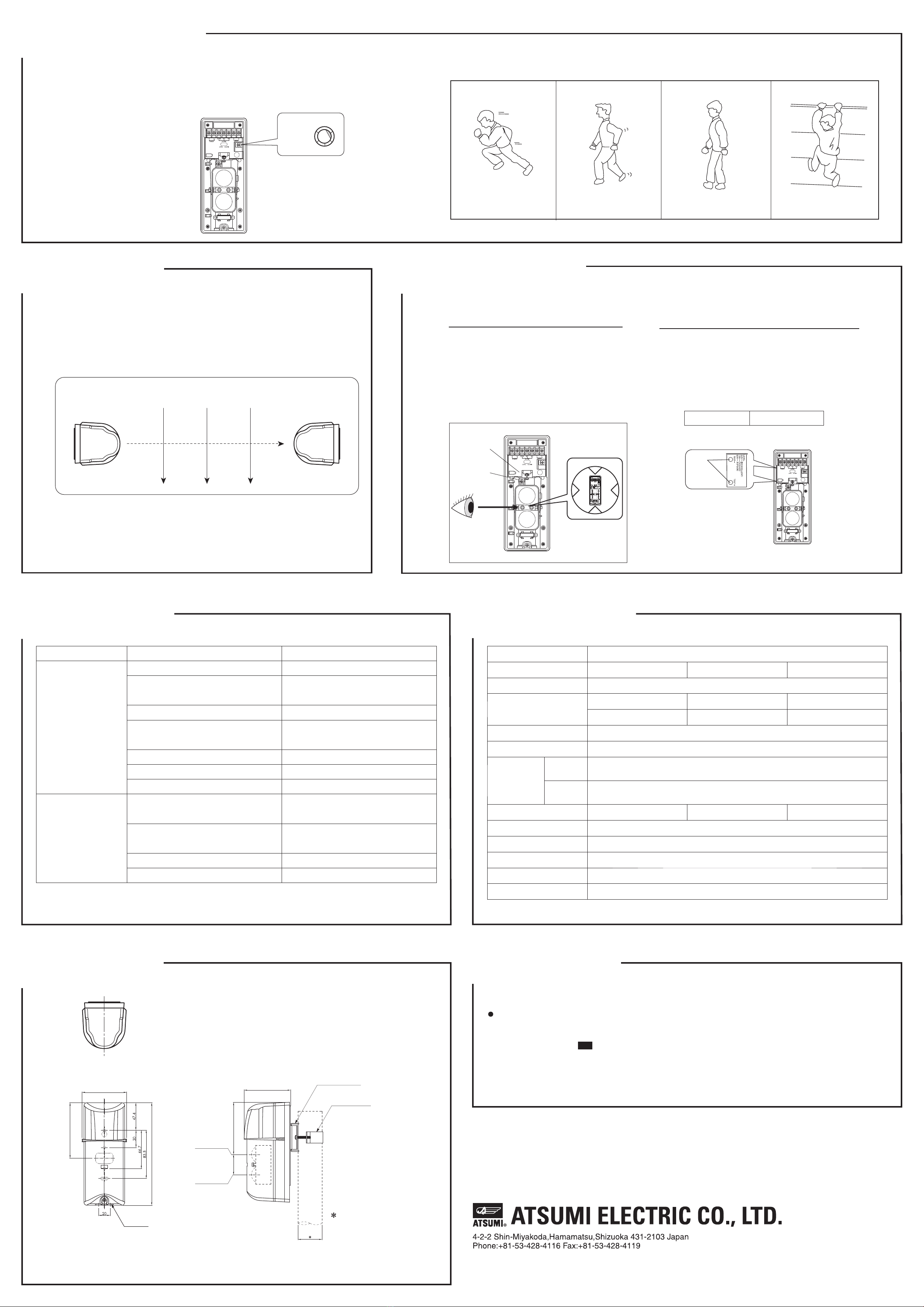
SENSITIVITY ADJUSTMENT
6
It is possible to adjust the detection sensitivit y by adjusting the interruption
When the unit is mounted on a wall, the interruption time can be set longer because the intruder cannot move quickly. This way,
it is possible to prevent an erroneous operation by a bird, small animal,
Adjust the sensitivity with the moving speed of a possible intruder taken into consideration. Al so, be sure to check the unit for
operation after adjustment.
Fast running at full
speed (6.9m/s)
Scale 1 Scale 2 Scale 3 Scale 4~5
Walking with quick
steps (1.2m/s)
Normal walking
(0.7m/s)
Slow action
(0.3~0.5m/s)
Running Fast walking Normal walking Slow moving
OPTICAL AXIS ALIGNMENT
There are two ways for optical axis alignment, by using a level LED and a tester.
1. Using a level LED
Rough adjustment
While looking into the scope located in the center of the
lens 10 to 15 cm away from it, turn the turntable for adju-
stment in the horizontal direction and the vertical adju-
screw for adjustment in the vertical direction until
the detector on the other side is in the center
of the scope
as shown in the scope view shown below.
2. Using a tester
Fine adjustment
Insert the tester stick into the tester hole in the receiver to check
If the measured value is 1.9V or more, adjustment is completed.
Tester
8
time adjustment volume.
paper and other object that flies in.
TROUBLESHOOTING
False alarm is output
frequently.
No ala utput even whenrm is o
beam is interrupted
Possible cause
An obstacle exists between transmitter and receiver.
Optical axis alignment is incomplete.
Installation condition is unstable.
Distan tween transmitter and receiver exceedsce be
rated distance.
Beam is interfered with beam from another detector.
There is an electrical noise source in nearby area .
Sunlight enters receiver within ±3°angle..
There is a highly reflective wall in parallel with beam.
Reflectance of floor surface is high.
Beam is interfered with beam from another detector.
Height of installation position is inappropriate.
Solution
Remove obstacle.
<Note>
If the trouble remains unsolved even after taking above solution, please consult the dealer of your purchase .
9
P/N: W.97.2165 Rev.: A
Problem
Adjust optical axis so that it is on the other side of
reflection surface.
Adjust optical axis so that it is on the other side of
reflection surface.
Take proper measure to avoid beam interference.
Change installation position to a proper height .
Perform optical axis alignment again to obtain 1.9V
Change installation position
-30℃~+60℃, RH 95%or less
30m 60m 90m
Indoor / Outdoor(IP55)
Black Mansel approximation N1.0
the tester voltage.
Mount bracket
Mount plate
Center of the
Upper Beam
Center of the
Lower Beam
hole
stment
Turntable Scope view
adjustment
screw
Vertical
voltage is obtained.
If it is less than adjust the horizontal and vertical adjust-1.9V
ment s of the until 1.9V or more screw transmitter and receiver
and receiver,
INTERRUPTION
TIME 1
2
3
4
5
2.2V~:execellent
Rough adjustment is OK when level LED turn off. 1.9V~:good
77
96
17 7
83
9336
This manual suits for next models
2
Other Atsumi Electric Security Sensor manuals


Popular Security Sensor manuals by other brands


urmet domus
urmet domus 1067/024 manual

DSC
DSC LC-102PIGBSS installation instructions

Gas Clip Technologies
Gas Clip Technologies Multi Gas Clip user manual

ZiLOG
ZiLOG ZMOTION quick start guide

Clas Ohlson
Clas Ohlson ST-09 instruction manual

Preifer Vaccum
Preifer Vaccum SmartTest HLT 570 operating instructions

Panasonic
Panasonic ST4 Series instruction manual

Jung
Jung FPM360WW operating instructions

Politec
Politec MANA MW installation manual

Treasure Cove
Treasure Cove Vibra-Tector 730 quick start guide

Conrad
Conrad FAZ 3000-TF-2 operating instructions

FT Technologies
FT Technologies Acu-Res Acu-Vis 2.0 user manual