Atsumi Electric IR36E User manual

ATSUMI ELECTRIC CO., LTD.
4-2-2 SHIN-MIYAKODA, HAMAMATSU, SHIZUOKA 431-2103 JAPAN PHONE:053-474-1173 FAX:053-474-1177
1For Safety Installation
1. Read the following carefully prior to installation.
Attention !
■Do not install outdoors.
■Avoid intense shock or vibration.
■Avoid intense electrical or electromagnetic noise.
■Avoid magnetic materials.
■Avoid corrosive gas and dust.
■Avoid direct sunlight and intense headlight.
■Do not install in the areas where sudden temperature fluctuation is expected.
■Do not install in the area where dewing is expected such as refrigerator.
■Install within 2.5 - 6 meter height from floor.
■Install and set up so that burglars will cross field of view.
■Avoid partitions, furniture and blocking objects within coverage.
■Detecting performance is based upon temperature difference between moving object such as human being and stable
■background. When the difference is greater, actual coverage may be wider.
2. Read the following prior to installation and regular maintenance.
Warning !
■Do not perform installation when it thunders.
■Do not disassemble or modify the unit.
■Electricity must be cut off during installation.
■Keep power between 9 - 18 VDC anytime.
Attention !
■Avoid intense shock and vibration.
■After installation and setup, make sure of performance and appropriate coverage of the unit by walk test.
■Mirror, partition or wall that may reflect well will cause inappropriate coverage.
■Remove partitions, furniture and objects that may block coverage.
■Use blinds or curtain to avoid direct sunlight or intense headlight.
■Avoid fax machine, heater or air conditioner that may cause heat fluctuation.
3. Other attention
■Moving object cannot be detected in gap of detecting zones.
■Static object including human body cannot be detected.
■Static human body could be detected in case its temperature fluctuates.
■Moving object could not be detected when its temperature is close to that of stable background.
2COMPONENTS
Make sure that the following items are included in the package prior to installation.
Description
Detector (Base & Sensor)
Mounting Screw (Ø4)
Quantity
1 each
2 each
Description
Operation Manual Quantity
1 each
*Screws are put on packing material.
PASSIVE INFRARED DETECTOR
IR36E
INSTALLATION INSTRUCTIONS
We appreciate your purchase of ATSUMI PASSIVE INFRARED DETECTOR.
Please read the following installation instructions carefully for appropriate use of the product.
1

3PARTS DESCRIPTION
1Sensor unit
2Base unit
3LED for Alarm/Memory(Red)
4Knockout
5Lock screw
6Terminals
7Dip switches
4
1. Terminals
WIRING
Description
1Power (+)
2Power (-)
3Alarm output (NC)
4Alarm output (COM)
5Alarm output (NO)
67Tamper
8Alarm memory
•3- 4:Form B, N.C.
•4- 5:Form A, N.O.
•
Contact Rating:30VDC,0.1A for Resistive Loads
•Both‘‘3- 4’’and‘‘4- 5’’open when
power is not supplied.
•
N.C. opens when the sensor unit is removed.
•
Contact Rating
:
30VDC, 0.1A for Resistive
Loads
Please see‘‘6. Functions’’ for details.
9 - 18 VDC
Function
Wire size
0.3mm2or Ø0.65(AWG22)
0.5mm2or Ø0.8(AWG20)
*When two or more units are used on one wire, the maximum distance is obtained by dividing the above distance by the
*number of units.
Distance at 12 VDC
850 m
1,300 m
2. Wire Distance
3. Wiring samples
(1) 1 detector (3- 4, Form B used)
1Sensor unit
2Base unit
Power
Output
Alarm
Input
Tamper
Controller
Detector
2

(2) 2 detectors (3- 4, Form B used)
To maintain stable performance, use the same kind of wire for all purposes, Power, Tamper, Alarm and Alarm memory.
■Do not supply power until all wiring is completed.
■Connect the unit to a UL listed power supply or control panel capable of providing stand-by power for at least 4 hours.
■Refer to the National Electrical Code, NFPA70.
5INSTALLATION
1Loosen the lock screw then turn the sensor unit counter-
clockwise to remove it from the base unit. 2Mount the base unit on ceiling and connect the wire to the
unit.
3Perform initial setup. Please see‘‘7. Initial setup’’ for details.
4Determine coverage. Please see‘‘8. Determining Coverage’’ for details.
5Mach direction of both arrows then align V-shaped protrusion A of the sensor unit with Mark B of the base unit. Then turn the
sensor unit clockwise until matching Mark C.
6Mount the sensor unit to the base unit using the lock screw.
Install the unit so that intruders will cross field of view. Please see Section ‘‘11 Coverage’’ for details.
Detector Detector
Power
Output
Alarm
Input
Tamper
Controller
Wiring hole
Arrows
Mark B
Mark C
V-shaped protrusion A
Knockout
3
6FUNCTIONS
1. PULSE COUNT functions to trigger the unit based on desired number of pulse.
1) Select number of pulse, either 1 or 2, using Dip switch 1.
2) The unit will be triggered when pulse count within 10 seconds reaches the specified number. Count will be reset 10 seconds
after the last pulse.
Usually 1 - 3 pulses are counted when human body crosses a field of view. However, there may be a case where
only one pulse is counted when temperature difference between human body and stable background is small.
Please take this into your consideration for appropriate setup.
2. ALARM MEMORY functions to identify the triggered detector(s) when two or more units are connected in one loop.
1) Appropriate wiring with Memory terminal is required.
2) Alarm output will be memorized when both terminals are disconnected.
3) LED will light to indicate the memory while both terminals are connected.
4) Memory will be reset and the LED will be turned off when power is cut off or both terminals are disconnected.
3. SELF-DIAGNOSTIC CIRCUIT functions to detect malfunction of the unit itself.
1) This will function anytime regardless of setup and condition of the unit.
2) LED will flicker to indicate malfunction with terminals or amplifier.
3) Flickering LED and alarm output will continue until power is cut off.
4) LED will flicker regardless of condition of the unit during 30 second warm-up.
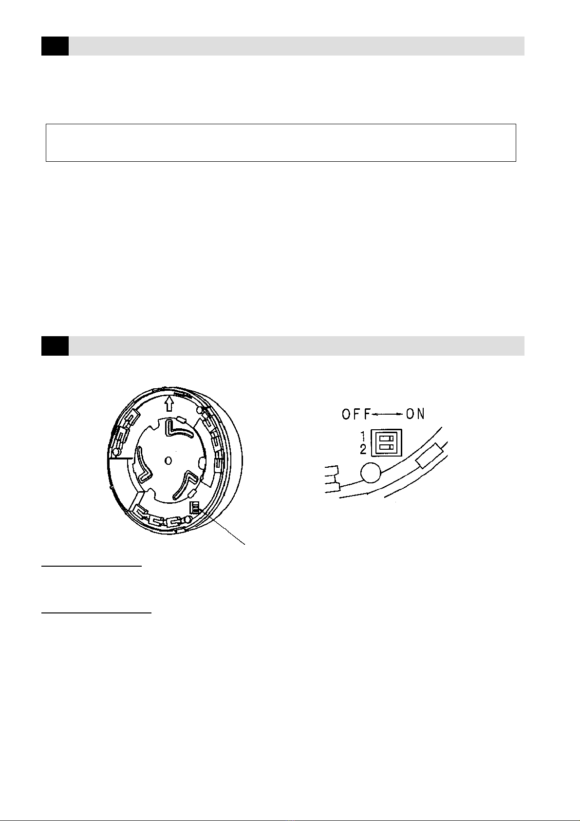
7INITIAL SETUP
All dip switches are ON when shipped from factory.
Switch 1: PULSE COUNT
ON :The unit will be triggered with one pulse.
OFF:The unit will be triggered with two pulses within 10 seconds.
Switch 2: ALARM MEMORY
ON :LED will light only when triggered.
OFF:LED will never light.
NOTE:Regardless of dip switch setup, LED will light or flicker in the following cases.
1During 30 second warm-up
2When alarm memory is indicated
3When Self-Diagnostic Circuit functions
Dip switches
4

8DETERMINING COVERAGE
This unit allows for 360 degree coverage mounting three(3) 120 degree optical assemblies. You can adjust the mirrors either
simultaneously or independently.
1. SIMULTANEOUS SETUP
Rotate the adjusting plate to align V-shaped protrusion with the desired mounting height. In this case, coverage of 20 meters
in diameter is achieved.
2. INDEPENDENT SETUP
1Rotate the adjusting plate clockwise until V-shaped protrusion reaches‘‘Free’’position. Each mirror is then adjustable
independently.
2Determine the rod position from the desired Mounting Height & Max. Range shown on the adjusting plate.
NOTE : Arrows and their area numbers are indicated on the label of the base unit. Each arrow is centered in each coverage
of 120 degrees and its number stands for each one of three(3) areas. The same numbers are also marked on the
adjusting plate of the sensor unit to match each other when fixed together.
Adjusting plate
Rod Area number
V-shaped protrusion
Arrow and area number
Align the rod to C position
for 4 meter height and 8
meter coverage.
9WALK TEST
1Make sure that the dip switch 2 is ON.
2Wait for 30 seconds after Power is turned on. (LED will flicker for 30 seconds.)
3Make sure that LED lights when you walk in coverage.
4In case LED does not light, adjust coverage and pulse count until it works properly.
In order to rotate the adjusting plate counterclockwise from‘‘Free’’position, all rods must be returned to the
center ends.
5

10 TROUBLE SHOOTING
SYMPTOM
The unit does not detect or LED
does not light.
The unit detects occasionally.
False Alarm (The unit detects
against nobody.)
LED lights with no alarm output.
LED lights with no alarm output. (In
case COM and NC are used for
alarm output.)
LED flickers sending alarm output.
POSSIBLE CAUSE
Blocked by partitions or other objects.
Dip switch 2 is OFF.
Intruder does not cross field of view.
Installed too close to electrical noise or
wired too close to the power or power
line.
Sudden temperature fluctuation
Direct sunlight or intense headlight
Sensor and Base unit are not securely
fixed.
Controller is not armed.
Disconnection, Poor connection, Short
or Poor insulation of the wire
Alarm output is connected in parallel with
that of other unit(s).
Self-Diagnostic circuit is activated.
11 COVERAGE
Side View
The unit must be installed so that intruders
will cross field of view. Failure of this doing
may end up mis-alarm.
When the coverage is blocked with partitions
or furniture, the unit does not detect over
them. Move the unit or install two or more
units to maintain the desired coverage.
Top View Mounting height 20ft.(6m)
Mounting height 8ft.(2.5m)
REMEDY
- Remove blocking objects.
- Reset coverage.
Turn the switch to ON.
Reset coverage.
- Install in other place.
- Change the wiring route.
- Remove heat source.
- Reset coverage.
- Reset coverage.
- Block the light using blinds, etc.
Make sure to fix them together.
Arm the controller.
Check with Tester, then fasten terminal
screws securely.
- Wire the outputs in series.
- Connect one unit only in one loop.
Replace the unit.
66ft.
(20m)
2.3ft.
(0.7m)
A-A
A-A
B-B
B-B
3ft.
(0.9m)
33ft.
(10m) 33ft.
(10m)
0
33ft.
(10m) 33ft.
(10m)
0
33ft.
(10m) 33ft.
(10m)
0
3.6ft.
(1.1m)
33ft.
(10m) 33ft.
(10m)
0
6

12 DIMENSIONS
Unit : inch(mm)
PASSIVE INFRARED DETECTOR
IR36E
9 ~ 18 VDC
25 mA (Max)
-4 ~ +122°F (-20 ~ +50°C), RH35 ~ 95%, Non-condensing
-4 ~ +140°F (-20 ~ +60°C), RH35 ~ 95%, Non-condensing
Ø20 m (Ø66 ft.) 360°
132 zones (66 pairs)
Passive Infrared
- Warm-up (30 seconds): Flickers
- Alarm: Lights
- Alarm Memory: Lights
- Self-Diagnostic: Flickers
Å@Form 1a/1b
- 3 seconds
- 30 VDC, 0.1A for Resistive Loads
- 6.0 ±1Ω
Å@Form 1b
- Open while the sensor is detached from the base.
- 30 VDC, 0.1A for Resistive Loads
- 0.5 ±0.5Ω1 ~ 6.6ft./sec. (0.3 ~ 2.0 m/sec.)
Over 2.7°F(1.5°C) difference against stable background
at 3.3ft.(1m)/sec.under Environmental condition of 95°F(35°C)
16.8°vertically
Ceiling, Indoor, Mounting height 8 ~ 20ft. (2.5 ~ 6m)
230 g
13 SPECIFICATIONS
Description
Model
Power input
Current draw
Operating Temperature & Humidity
Storage Temperature & Humidity
Coverage
Detecting zone
Detection method
LED indication
Alarm output
Tamper
Detectable Speed
Sensitivity
Adjustable mirror range
Mounting
Weight
*Specifications and design are subject to change without prior notice.
Ø5.71
(Ø145)
2.56
(65)
Ø0.94 Wiring hole
(Ø24)
0.18
(45)
Ø0.34
(Ø8.6)
2.63
(66.7)
25°
7

14 MAINTENANCE
* Coverage should be checked in accordance with ‘‘9. WALK TEST’’ at least once a week.
NOTE : This unit is designed to detect movement of an intruder and activates an alarm control panel.
Being only a part of a complete system, we can not take responsibility for any damages or other consequences
resulting from an intrusion.
ATSUMI ELECTRIC CO., LTD.
AE0141811
99.3 2000
4-2-2 SHIN-MIYAKODA, HAMAMATSU, SHIZUOKA 431-2103 JAPAN
PHONE:053-474-1173 FAX:053-474-1177
Table of contents
Other Atsumi Electric Security Sensor manuals


Popular Security Sensor manuals by other brands


Optex
Optex VX-402R installation instructions

DSC
DSC WLS904PL-433 installation instructions

elsner elektronik
elsner elektronik Intra-Sewi KNX L-Pr Installation and adjustment

Aprilaire
Aprilaire Z10IDT Installation and operator's manual

AECO
AECO SC30P-RE25 T AD3 operating instructions

Bullard
Bullard CAB15RAUPGRADE instructions