Shock /Glass AdjustmentUseonlyduring testing and setting
SHOCK -foradjustmentofthe
frequencysensitivitywith
potentiometer“SHOCK”
SETTING -UPTHEDETECTOR
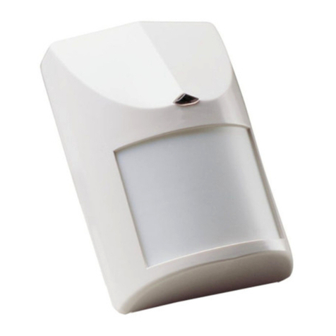
PIRSENSITIVITYADJUSTMENT:Switch3ofDIP-4.Use forSetting ”PULSE”-providessensitivitycontrolofPIRaccording tothe environment.
Position Left -”On”-High sensitivityForstableenvironments.Position Right-”OFF”-LowsensitivityForharshenvironments.
“PIRCAL”POTENTIOMETERADJUSTMENT:According toprotected area range.Usethe potentiometermarked “PIRCAL”toadjustthe detection
sensitivitybetween 15%and 100%according towalktestintheprotected area.(Factorysetting is57%).Rotatethe potentiometerclockwisetoincrease
range,counter-clockwisetodecreaserange.Always walktestand re-adjustifrequired.
LEDINDICATIONOFALARMSIGNAL:Switch1ofDIP-4.Use forSetting “LED”-providescontrolofAlarmsignalLEDindication.
PositionLeft -“On”-LEDenable.PositionRight“OFF”-LEDdisable.
SOUND SENSITIVITYADJUSTMENT:Switch2ofDIP-4.Use forSetting“AUDIO”-providescontrolofsound detection sensitivity.Position Left -
“On”-reducing the sensitivityofsound detection by50%.(Useinsmall room).Position Right“OFF”-Sensitivityofsound detection 100%.
PETIMMUNITYSETTING:Switch4ofDIP-4.Use forSetting “PET”15kg-25kg.Position Left “ON”ImmunitytoPETup to15 kg.
PositionRight“OFF”ImmunitytoPETup to25 kg
TEST PROCEDURES
Waitforone minutewarmup timeafterapplying 12-Vdcpower.Conducttesting withthe protected area cleared ofall people.Makesuretotestthe unit
thoroughlyforproperdetection.
Walktest: 1.Removefrontcover.Set“PULSE”to“ON”position,and set“LED”to“ON”position.2.Replacethe frontcover.3.Startwalking slowly
across the detection area.4.Observethatthe red led lightswhenevermotion isdetected.5.Allow5sec.between eachtestforthe detectortostabilize.
6.Afterthe walktestiscompleted,you can setthe“LED”to“OFF”position.
NOTE:Walktestsshouldbe conducted,atleastonceayear,toconfirmproperoperation and coverage ofthe detector.
ADJUSTMENT
GLASS -foradjustmentof
thehighfrequencysensitivity
withpotentiometer“GLASS”
NORMAL-
forregular
operation
Glass Break adjustment
Toadjustthe glassbreaksensitivity,placethe jumperaccordinglyGLASS TESTmarking.Green (SHOCK)
LEDisconstantlyON.Nowyou canadjustthe sensitivitybyrotating theGLASS CALpotentiometer.Operate
the Sound BreakSimulator*nearthe protected windowand rotatethe potentiometerGLASS CALclock-
wisetoincreasesensitivity,and counter-clock-wisetodecreasesensitivityuntil the Yellowand Red LEDs
areilluminating foreachglassbreaksound.
Note:When the jumperissetforGLASS adjustment, onlythe high frequencysound ofbreaking glass is
detected.*It isrecommended touseGLASS-BREAK SimulatorFG-701 (CROWp/n004001)
ShockAdjustment
Toadjustthe shock setting (increase/decreasesensitivity)placethe jumperaccordinglySHOCKTEST
marking-Yellow(GLASS)LEDisconstantlyON.Nowyou can adjustthesensitivitybyrotatingthepotentiometer
SHOCKCAL.Hitgentlyontheprotectedglassand rotatethepotentiometerclock-wisetoincreasesensitivity,
and counter-clock-wisetodecreasesensitivityuntil the Green and Red LEDsareilluminating foreachhit.
Note:When the jumperissetforSHOCKadjustment, onlythe lowfrequency ofthe shock signalpriorto
glassbreakage isdetected.
SHOCK/GLASS TEST PROCEDURE
FinalTesting
*Makesuretosetjumper“GLASS/SHOCK”inposition NORMAL.When the jumperisinthisposition,the
detectorwill detectbothshockand soundfrequencies.*Toensuremaximumprotectionagainstfalsealarms,
activateanydeviceinthe area,whichmightautomaticallycyclepumps,gene
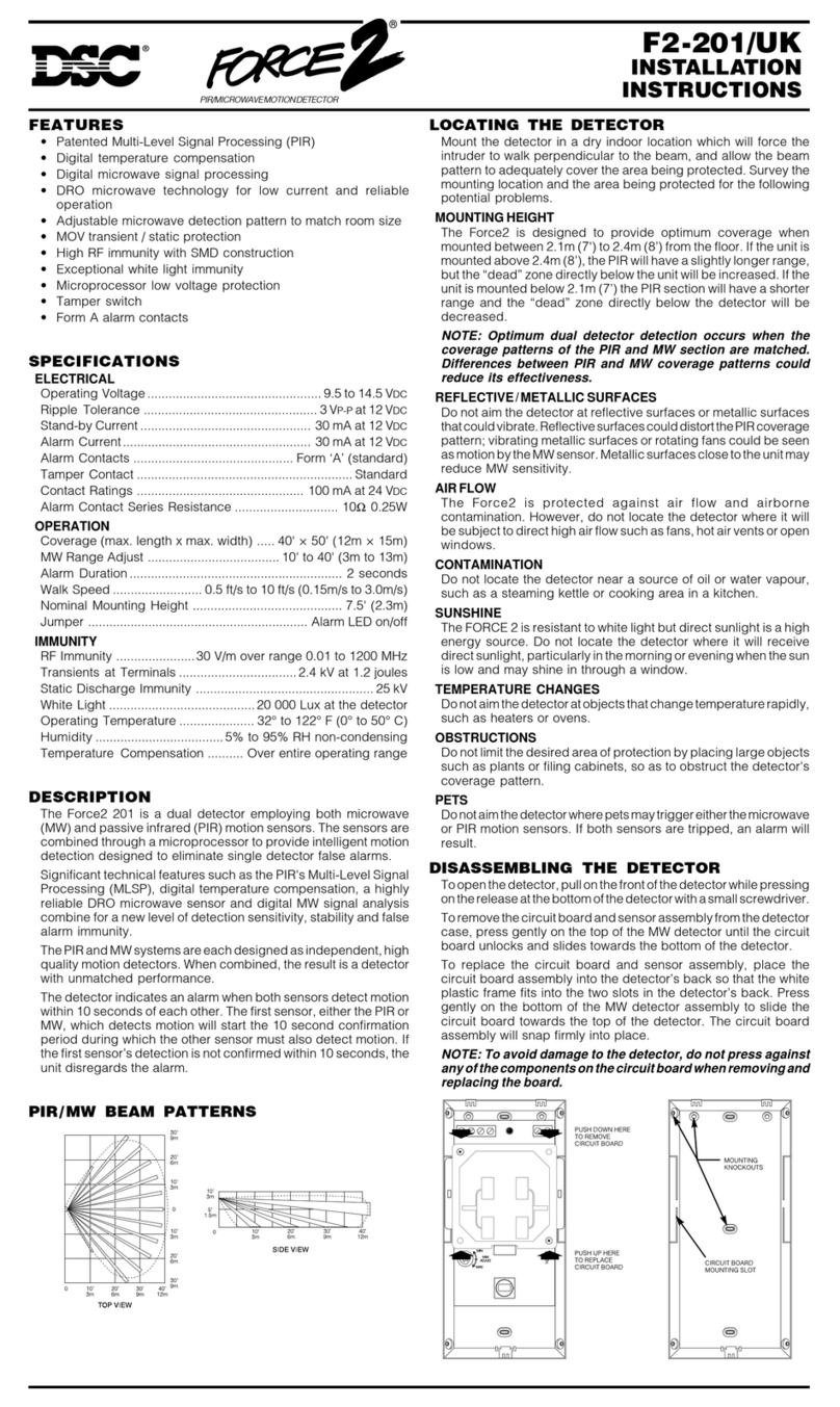
Warm UpPeriod 60 sec
RFIProtection 30V/m10-1000MHz
EMIProtection 50,000Vofelectricalinterferencefromlighting
VisibleLight
Protection stableagainsthalogen light2.4m(8ft)orreflected light
Detection rangeGlass upto10m(900);PIRupto15m(WAlens)
LEDsindicatorYellowLED(GLASS)-glassbreaksignalfortesting&adjustment
GreenLED(SHOCK)-shock signalfortesting &adjustment
RedLED(ALARM) -alarm signal:
Fleshing light-glass&breakdetection orglass &shock &PIR
detection
Constantlight-PIRdetection
Dimensions118mm x62.5mm x41mm (4.65”x2.46”x1.61”)
Weight110 gr.
TECHNICALSPECIFICATION
Detection Method Quad(Fourelement)PIR&electretmicrophone
Detection Speed0.15-3.6m/sec
PowerInput8.2-16 Vdc
CurrentDrawAlarm PIR:16.5mA;Alarm Shock&Glass
22mA;Alarm all:18mA
Standby:16.5mA
BIDirectional
Temp.
Compensation YES
Pulse Count1,AUTO
Alarm Period 2sec
Alarm OutputN.C28Vdc0.1Awith10Ohmseriesprotection
resistors
TamperSwitchN.C28Vdc0.1Awith10 Ohmseriesprotection
resistor-openwhen coverisremove
NORMAL
GLASS
TESTSHOCK
TEST
GLASS
TESTSHOCK
TEST
NORMALNORMAL
GLASS
TESTSHOCK
TEST
BLOCK CONNECTOR
PYROSENSORSWITCH FOR
SETTINGS
FIG 8-PCBLAYOUT
LIMITEDWARRANTY:DigitalSecurityControlsLtd,warrantsthatforaperiod of12 monthsfromthe dateofpurchase,the productshall be free ofdefectsinmaterialsandworkmanshipundernormaluseand thatinfulfillmentofany
breachofsuchwarranty.DigitalSecurityControlsLtdshall,atitsoption,repairorreplacethe defectiveequipmentupon returnsofthe equipmenttoitsrepairdepot. Thiswarrantyappliesonlytodefectsinpartsand workmanshipandnotto
damage incurred inshippingorhandling,ordamage due tocausesbeyond the controlofDigitalSecurityControlsLtd,suchaslightning,excessivevoltage mechanicalshock,waterdamage,ordamage arising outofabuse,alteration or
improperapplication oftheequipment.
Theforegoingwarrantyshall applyonlytothe originalbuyer,and isand shall be inlieu ofanyand all otherwarranties,whetherexpressed orimplied and ofallotherobligationsorliabilitiesonthepartofDigitalSecurityControlsLtd.Digital
SecurityControlsLtdneitherassumesresponsibilityfor,norauthorizesanyotherperson purporting toacton itsbehalftomodifyortochange thiswarranty,nortoassumeforitanyotherwarrantyorliabilityconcerning thisproduct.
InnoeventshallDigitalSecurityControlsLtdbe liableforanydirect,indirectorconsequentialdamages,lossofanticipatedprofits,lossoftimeoranyotherlossesincurredbythebuyerinconnection withthepurchase,installation oroperation
orfailureofthisproduct.
Motion detectorscan onlydetectmotion withinthe designated areasasShownintheirrespectiveinstallationinstructions.Theycannotdiscriminatebetweenintrudersand intended occupants.Motion detectorsdonotprovidevolumetricarea
protection.Theyhavemultiplebeamsofdetection and motion can onlybe detectedinunobstructedareascovered bythesebeams.Theycannotdetectmotion whichoccursbehind walls,ceilings,floor,closed doors,glasspartitions,glass
doorsorwindows.Any
type oftampering whetherintentionalorunintentionalsuchasmasking ,painting,orspraying ofanymaterialon the lenses,mirrors,windowsoranyotherpartofthe detection systemwill impairitsproperoperation.
Passiveinfraredmotion detectorsoperatebysensingchangesintemperature.Howevertheireffectivenesscan be reduced whentheambienttemperaturerisesnearorabovebodytemperatureorifthereareintentionalorunintentionalsources
ofheatinornearthedetectionarea.Someoftheseheatsourcescouldbeheaters,radiators,stoves,barbeques,fireplaces,sunlight, steamvents,lighting and soon.
WARNING:DigitalSecurityControlsLtd,recommendsthattheentiresystembecompletelytestedon aregularbasis.However,despitefrequenttesting,anddueto,butnotlimitedto,criminaltampering orelectricaldisruption,
itispossibleforthisproducttofail toperformasexpected.
Importantinformation:Changes ormodificationsnotexpresslyapprovedbyDigitalSecurityControlsLtdcouldvoidtheuser'sauthoritytooperatethisequipment.
2005 DigitalSecurityControlsLtd
Toronto,Canada
www.dsc.com
