attika Viva 100 L G User manual

1
BRUGERMANUAL
BEDIENUNGSANLEITUNG
USER MANUAL
MANUEL D’UTILISATEUR
BRUKERVEILEDNING
BRUKSANVISNING
KÄYTTÖOHJE
GEBRUIKERSHANDLEIDING
POSITIV
OUTLINE
NEGATIV
VIVA L GAS

2
Product ID: 0359CS1717
Produced at:
RAIS A/S, Industrivej 20, 9900 Frederikshavn, Danmark
Hergestellt für /Produced for:
ATTIKA FEUER AG, Brunnmatt 16, CH-6330 Cham / RAIS A/S, Industrivej 20, DK-9900 Frederikshavn
CE Label:
VIVA 100 L Gas, VIVA 100 L G Gas, VIVA 100 L Classic Gas, VIVA 100 L G Classic Gas
VIVA 120 L Gas, VIVA 120 L G Gas, VIVA 120 L Classic Gas, VIVA 120 L G Classic Gas
VIVA 160 L Gas, VIVA 160 L G Gas, VIVA 160 L Classic Gas, VIVA 160 L G Classic Gas
17
C11
C31
C91
0359/
This appliance must be installed in accordance with the rules in force, and only used in
a suffidebtly ventilated space. Consult instructions before installation and use of this
appliance. Tested and Certified for use on Biopropane.
Efficiency class 1
N
A
T
U
R
A
L
P
R
O
P
A
N
E
GAS CATEGORY and SUPPLY PRESSURE
I2H
I2E
I2E+
I2ELL
I2L I2EK
I2 (43.46 -45.3 MJ/m3
(0°C))
I3+
I3P(30)
I3P(37)
I3P(50)
I3B/P(30)
I3B/P(50)
HEAT
INPUT
(Gross, KW)
BURNER
PRESSURE
(Hot, mbar) COUNTRY
of DESTINATION
G20 @ 20 mbar
G20 @ 20 mbar
G20↔G25 @
20↔25 mbar
G25 @ 20 mbar
G20/G25.3 @
25 mbar
G30↔G31 @
28↔37 mbar
G31 @ 30 mbar
G31 @ 37 mbar
G31 @ 50 mbar
G30↔G31 @
30 mbar
G30↔G31 @
50 mbar
9,1
9,1
9.1/8.4
7,5
8,5
8
7
8
8
8
836
27
36
36
28
27/36
16.6
13.4
13.2/16.4
13,2
13,2
AT, BG, CH, CZ, DK, EE, ES, FI,
GB, GR, HR, IE, IT, LT, LV, NO,
PT, RO, SE, SI, SK, TR
DE, LU, PL, RO
BE, FR
DE
NL
BE, CH, CY, CZ, ES, FR,
GB, GR, IE, IT, LT, PT, SI,
SK, TR
FI, NL, RO
BE, CH, CZ, ES, FR, GB,
GR, HR, IE, IT, LT, NL, PL,
PT, SL, SK, TR
AT, CH, CZ, DE, NL, SK
BE, BG, CY, DK, EE, FI, FR, GB,
GR, HR, HU, IT, LT, MT, NL, NO,
RO, SE, SI, SK, TR
AT, CH, CZ, DE, FR, SK
VIVA 100 L Gas / VIVA 100 L G Gas / VIVA 100 L Classic Gas / VIVA 100 L G Classic Gas
VIVA 120 L Gas / VIVA 120 L G Gas / VIVA 120 L Classic Gas / VIVA 120 L G Classic Gas
VIVA 160 L Gas / VIVA 160 L G Gas / VIVA 160 L Classic Gas / VIVA 160 L G Classic Gas
Mærkeplade/Typenschild/Manufacturer’s plate/Plaque signalétique/
Merkeplate/Märkplät/ Tyyppikilpi
English RAIS/
attika
- U
ser manual for VIVA L Gas

English RAIS/
attika
- U
ser manual for VIVA L Gas
This stove had been tested and certied for several countries (see the rating plate).
It may be necessary to adjust the stove for safe and correct use in your country/
area.
This stove has been tested and certied for use with natural gas, LPG and biopro-
pane.
Biopropane can be used if the stove is adjusted for use with LPG (liquid petroleum
gas), see rating plate under PROPANE.
This manual covers the following models:
Viva 100 L Gas – without side glass
Viva 100 LG Gas – with side glass
Viva 100 L Classic Gas – without side glass
Viva 100 LG Classic Gas – with side glass
Viva 120 L Gas – without side glass
Viva 120 LG Gas – with side glass
Viva 120 L Classic Gas – without side glass
Viva 120 LG Classic Gas – with side glass
Viva 160 L Gas – without side glass
Viva 160 LG Gas – with side glass
Viva 160 L Classic Gas – without side glass
Viva 160 LG Classic Gas – with side glass

4
0
17-08-2017
3716510 - Viva L GAS
Revision :
Date :
English RAIS/
attika
- U
ser manual for VIVA L Gas
INTRODUCTION�����������������������������������������������������������������������������������������������������������������5
GUARANTEE���������������������������������������������������������������������������������������������������������������������������6
SPECIFICATIONS ���������������������������������������������������������������������������������������������������������������������7
DISTANCE/TEMPLATE��������������������������������������������������������������������������������������������������������������7
GENERAL
GENERAL REMARKS ���������������������������������������������������������������������������������������������������������������8
EMERGENCY INTERRUPTION OF GAS SUPPLY �������������������������������������������������������������������������9
INSTALLATION OF STOVE
INSTALLATION ����������������������������������������������������������������������������������������������������������������������10
GAS CONNECTION���������������������������������������������������������������������������������������������������������������10
VENTILATION������������������������������������������������������������������������������������������������������������������������10
GAS INSTALLATION���������������������������������������������������������������������������������������������������������������10
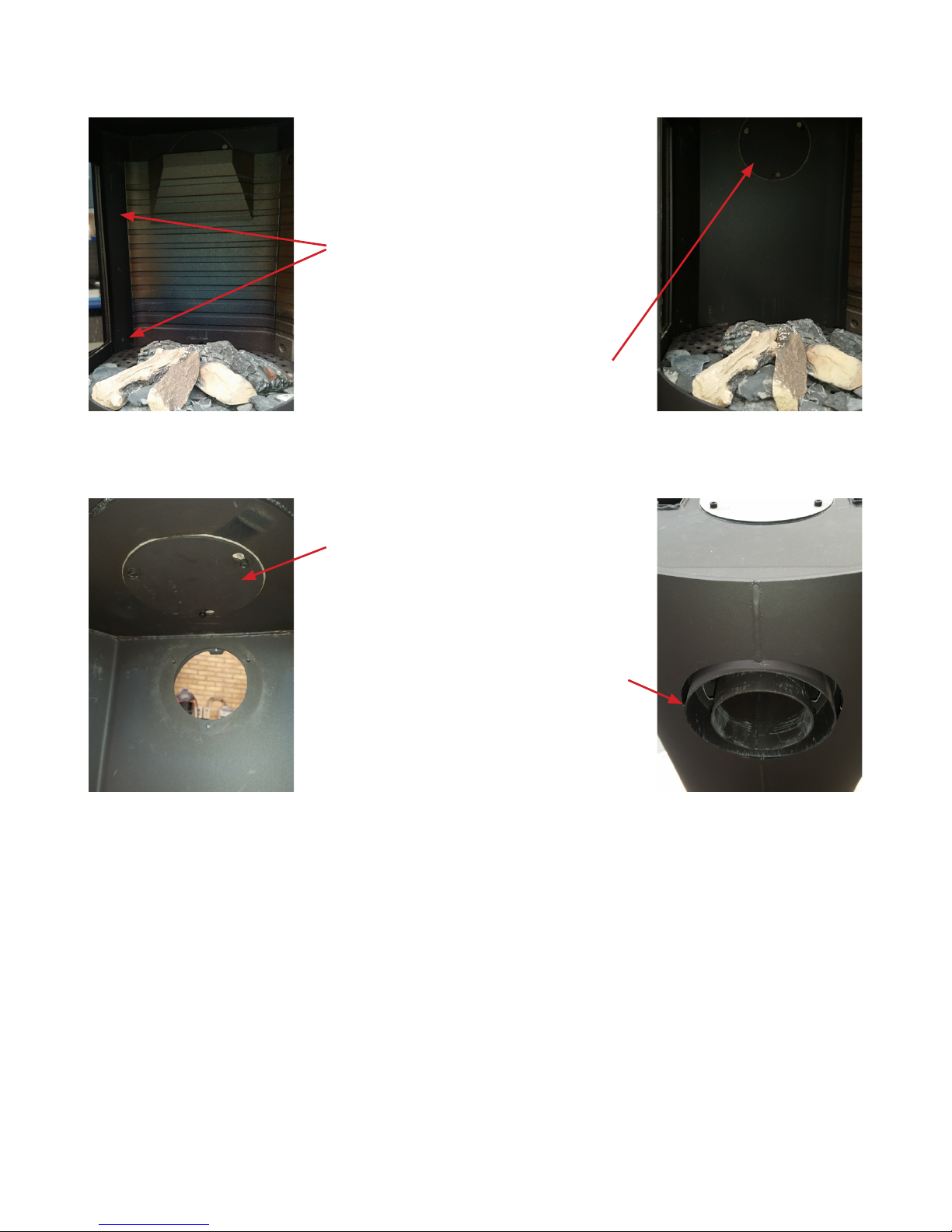
CHANGING THE CHIMNEY CONNECTION�����������������������������������������������������������������������������11
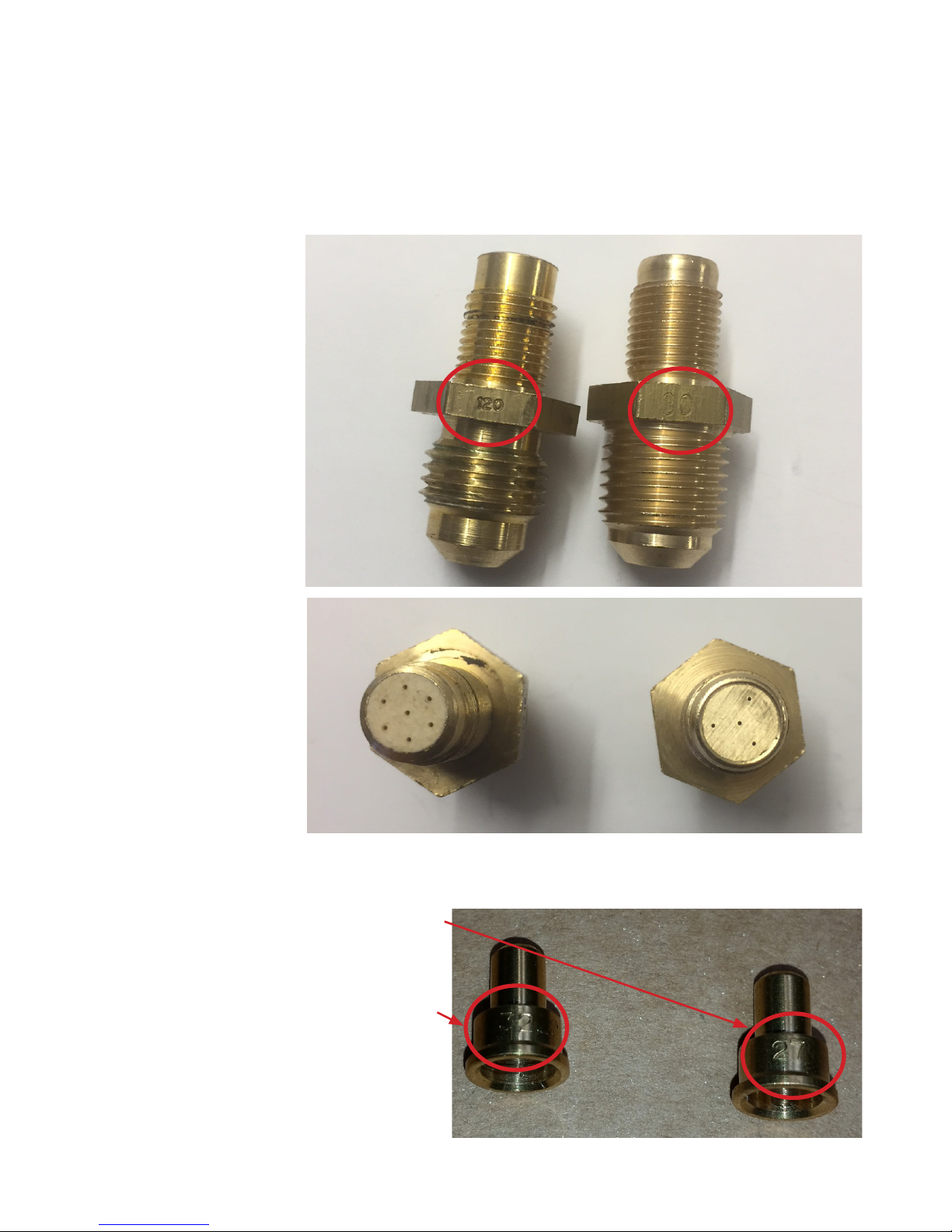
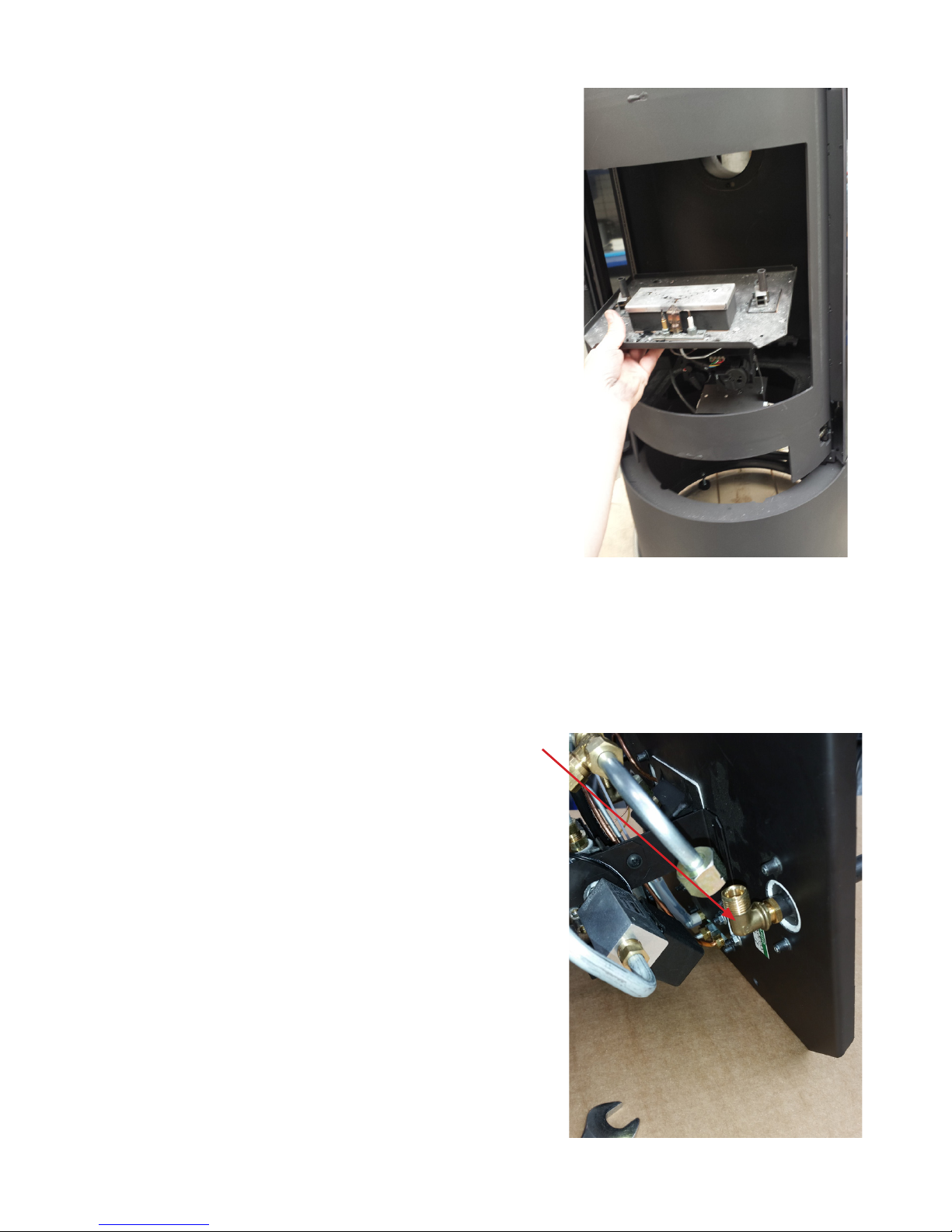
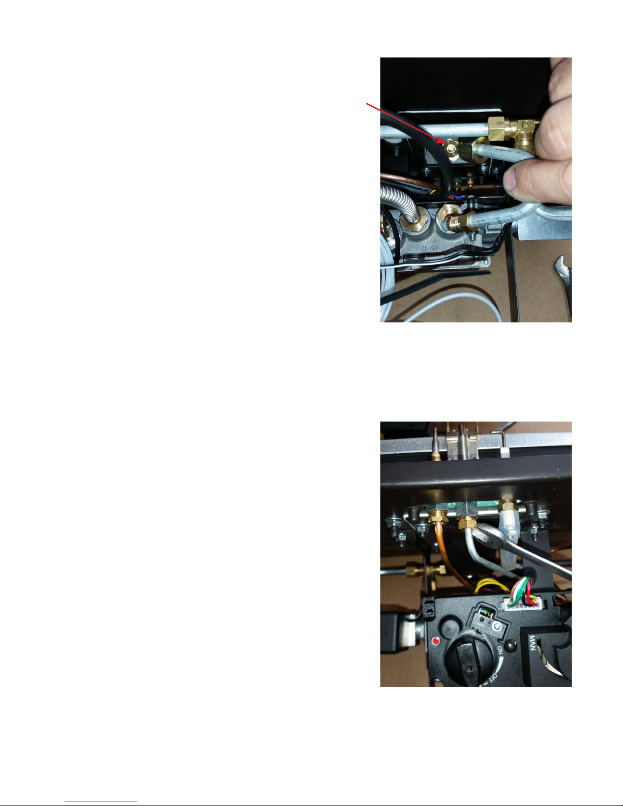
CONVERSION TO BOTTLED GAS (LPG) ����������������������������������������������������������������������������������14
NORMAL INSTALLATION - RECTANGULAR WITHOUT SIDE GLASS �����������������������������������������21
NORMAL INSTALLATION - RECTANGULAR WITHOUT SIDE GLASS �����������������������������������������22
CORNER INSTALLATION 45° WITHOUT SIDE GLASS���������������������������������������������������������������23
CORNER INSTALLATION 45° WITH SIDE GLASS ���������������������������������������������������������������������24
INSTALLATION SPACING FOR NON-FLAMMABLE WALL ���������������������������������������������������������25
CHIMNEY/VENT��������������������������������������������������������������������������������������������������������������������26
LOCATION OF CHIMNEY TERMINALS������������������������������������������������������������������������������������27
HORIZONTAL WALL TERMINAL TYPE C11 �����������������������������������������������������������������������������28
VERTICAL ROOF TERMINAL C31 �������������������������������������������������������������������������������������������29
ASSEMBLY OF SECONDARY BURNER ������������������������������������������������������������������������������������30
Arrangement of ”Embers” and ”Logs”���������������������������������������������������������������������������������31
START-UP
BATTERIES ����������������������������������������������������������������������������������������������������������������������������36
SETTING UP THE ELECTRONIC CODE ������������������������������������������������������������������������������������38
COMMISSIONING�����������������������������������������������������������������������������������������������������������������39
INITIAL IGNITION ������������������������������������������������������������������������������������������������������������������41
USER INSTRUCTIONS
REMOTE CONTROL���������������������������������������������������������������������������������������������������������������42
USING STOVE WITHOUT REMOTE CONTROL ������������������������������������������������������������������������48
SERVICE
SERVICE �������������������������������������������������������������������������������������������������������������������������������50
CLEANING����������������������������������������������������������������������������������������������������������������������������51
ACCESSORIES�����������������������������������������������������������������������������������������������������������������������52
MYFIRE WI-FI BOX ����������������������������������������������������������������������������������������������������������������53
SPARE PART LIST VIVA 100 L GAS - VIVA 120 L GAS - VIVA 160 L GAS ���������������������������������55
SPARE PART LIST VIVA 100 L G GAS - VIVA 120 L G GAS - VIVA 160 L G GAS ����������������������56
SPARE PART LIST GAS UNIT���������������������������������������������������������������������������������������������������57
TECHNICAL INFORMATION
TECHNICAL INFORMATION���������������������������������������������������������������������������������������������������58
TECHNICAL DATA�����������������������������������������������������������������������������������������������������������������60
EXAMPLES OF CHIMNEY SOLUTIONS������������������������������������������������������������������������������������62
CHIMNEY COMPONENTS �����������������������������������������������������������������������������������������������������68
DECLARATION OF CONFORMITY ������������������������������������������������������������������������������������������72
Reservations for printing errors�

Dealer: Date:
Introduction
Good luck with your new RAIS/
attika
Product�
A RAIS/
attika
stove is more than just a source of heat, it also expresses how you put
the emphasis on good design and high quality in your home�
In order get the most pleasure and benefit from your new stove, it is important that
you read the manual thoroughly before it is installed and put to use�
For the purpose of the guarantee and all contact regarding the stove in general, it is
important that you can state the stove's production number� We therefore recommend
that you write down the number in the form below�
The production number can be found at the bottom of the stove�
Installer: Date:
English RAIS/
attika
- U
ser manual for VIVA L Gas

6
Guarantee
RAIS/
attika
stoves are checked several times with regard to safety, as well as the
quality of materials and manufacturing� We offer a guarantee on all models and the
guarantee commences on the date of installation�
The guarantee covers:
• documented functional faults due to incorrect manufacture
• documented material faults
The guarantee does not cover:
• door and glass gaskets
• ceramic glass
• the appearance of the surface structure or texture of the natural stone
• the appearance of the stainless steel and colour changes and patina
• expansion blemishes
• batteries
The guarantee is invalidated in the event of:
• damage due to overfiring
• damage due to external influences and the use of unsuitable fuels
• failure to comply with statutory or recommended installation instructions and in
the event the user's own modifications of the stove�
• lack of servicing and care
In the event of damage, please contact your dealer� In the event of claims under the
guarantee, we will decide how the damage is to be repaired� In the event of repairs, we
will ensure they are performed professionally�
In the event of guarantee claims concerning repaired parts or parts delivered later,
please refer to national/EU law/provisions in relation to renewed guarantee periods�
The guarantee provisions applying at any time may be requested from RAIS/
attika
�
English RAIS/
attika
- U
ser manual for VIVA L Gas

7
English RAIS/
attika
- U
ser manual for VIVA L Gas
Specifications
Intertek Ref�: 102929617LHD-001
Viva 100 L Gas
Gas type G20
I2H/I2E
Viva 120 L Gas
Gas type G20
I2H/I2E
Viva 160 L Gas
Gas type G20
I2H/I2E
Nominal heat output (kW): 9�1 9�1 9�1
Min�/Max� Output (kW): 1�7 - 9�1 1�7 - 9�1 1�7 - 9�1
Heating area (m2at -20°): Approx� 180 Approx� 180 Approx� 180
Stove width/depth/height (mm): Ø470-1000 Ø470-1200 Ø470-1600
Weight (kg) min�, depending on model: approx� approx� approx�
Efficiency (%): 78�3 78�3 78�3
CO content (PPM) 31 31 31
NOx emissions 23 23 23
Flue gas temperature (°C): 210 210 210
Intertek Testing & Certification Ltd,
Registered office: Academy Place, 1 to 9 Brook Street, Brentwood, Essex
CM14 5NQ, United Kingdom� Registered No: 3272281
(England), VAT No: GB 672-7639-96-011
T: +44 1277 223 400
F: +44 1277 223 127
Distances/template
See scale drawings at back of the manual�
I: Distance from floor to flue outlet top
J: Distance from floor to centre flue outlet rear
L: Distance from floor to air intake back
M: Distance from centre flue outlet top to top plate rear edge
N: Distance from side to air intake at bottom

8
English RAIS/
attika
- U
ser manual for VIVA L Gas
General Comments
This RAIS/
attika
product is an extremely effective convection gas stove with a sealed
combustion chamber for chimneys with a balanced draught� It is fitted with a burner
with the latest burner technology� It has a variable heat output because it uses a special
control system that makes it possible to use three burners for high output or one burner
for a lower output� One of the burners, called the "Main burner" is located in the centre
of the stove, the second and third burners, called the "Secondary burners" are located
behind the Main burner� The secondary burners can be switched on and off while the
stove is on�
Where there is a natural gas connection, the local gas supply conditions should be inves-
tigated to ensure that the gas composition and pressure suit the stove's settings�
If the stove is connected to bottled gas, only gas bottles fitted with a gas regulator pro-
viding the correct gas pressure many be connected� For this reason, gas bottles without a
regulator must not be connected� (Low pressure regulator)
This stove must only be installed, set up and serviced by an authorised and qualified
plumbing and heating engineer/Gas installer� The installation must comply with local and
national Building Regulations and Gas Regulations and the user manual must be adhered
to� The user manual should be left with the customer, who should keep this for later use�
The manual is necessary when the stove is to be serviced�
Ensure that the chimney terminal is not blocked in any way and is free of vegetation
in the form of trees, bushes etc� and that objects are not resting against the chimney's
terminal or the protection around the terminal�
The door glass should always be cleaned before the stove is turned on and fingerprints
wiped as these can be burned into the glass�
The stove must not be used if the door glass is split, cracked, removed or if the door is
open� Do not use the stove if the door gasket is broken or worn�
This stove is designed for use in many different installation situations, which can be seen
in this manual� Only chimneys approved by RAIS/
attika
may be used with this product�
(see chimney section)
This stove is intended for chimneys with balanced draughts (Air intake and draught in
same chimney) so there is no need for any extra air supply for combustion� Suitable ven-
tilation is recommended in the room in order to achieve a pleasant living environment�
This product is a heating appliance so the surfaces become very hot and should not be
touched during use� It is therefore recommended that you use an approved stove screen
to protect children, older people and persons with reduced mobility in the same area as
the stove�
Keep curtains, washing, furniture etc� at a minimum distance of 300 mm from this stove�
The stove must not be used for burning waste�
If the stove is extinguished or goes out, do not attempt to turn it back on until a mini-
mum of 3 minutes have passed�
General

9
English RAIS/
attika
- U
ser manual for VIVA L Gas
Emergency interruption of gas supply
Where a smell of gas is detected, the gas supply must be interrupted
immediately�
Ventilate the room by opening windows and doors, do not use electrical
appliances in the vicinity of the stove� Send for an authorised Plumbing
and heating engineer/Gas installer�

10
English RAIS/
attika
- U
ser manual for VIVA L Gas
Installation
It is important that the stove is correctly installed from both an environ-
mental and safety point of view�
The stove must only be installed by an authorised gas installer
When installing the stove, all local rules and regulations, including those
referring to national and European standards must be complied with�
Local authorities and an authorised gas installer should be contacted
before installation�
There must be no unauthorised modifications of the stove�
Before installation begins, it should be confirmed that the information
on the data plate regarding gas type and pressure is in accordance with
the local gas supply conditions under which the stove is to be installed�
You should ensure that the gas supply can supply the required quantity
of gas and pressure as described on the data plate�
Gas connection
The pipe on the gas hose has an external diameter of Ø8mm�
Ventilation
This stove has a sealed combustion chamber and is intended for a bal-
anced draught� There is therefore no need for an extra air supply�
It is recommended that sufficient fresh air is supplied to the room to
maintain a comfortable environment�
This stove may be installed in a completely airtight building or a building
with mechanical ventilation�
Gas installation
Once it has been decided where the stove will be positioned, a gas in-
stallation should be established in the vicinity of the stove so that the gas
supply and stove can be connected�
As this stove has a sealed combustion chamber and a built-in plinth,
there is no need for a floor slab�
installation of stove

11
English RAIS/
attika
- U
ser manual for VIVA L Gas
PLEASE NOTE!
The floor construction must be able to bear the weight of the stove and
chimney, if applicable� If the existing design does not satisfy this prereq-
uisite, suitable measures must be taken (e�g�, a load distribution slab)�
Consult a construction expert�
The stove must be positioned at a safe distance from flammable materi-
al�
It must be ensured that flammable objects (e�g�, furniture) are not po-
sitioned closer than the distances stated in the following sections with
regard to installation (risk of fire)�
When you choose where you wish to position your stove, you should
consider the heat distribution to the other rooms� Then you will get the
maximum possible pleasure from your stove�
Inspect the stove for defects upon receipt�
Changes to chimney connection
The stove is supplied ready for a top outlet but can be changed to a
rear outlet in the following manner:
Illustrations
1� The knock-out blank at the rear of the stove
can be knocked out using a hammer� This may
require several blows� Be careful to only hit the
blank�

12
English RAIS/
attika
- U
ser manual for VIVA L Gas
2� Loosen the three
screws on the outer
flange on the top sur-
face of the stove� And
remove it�
3� Loosen the three
screws on the inner
flange on the bottom
surface of the stove�
And remove it�
4� Unscrew the outer cover
plate at the rear of the stove
and move it to the upper sur-
face of the stove�
5� To open the door, a 10mm
open-ended spanner is re-
quired to turn the two catches
at the top and bottom of the
door�
6� The secondary burners are
removed by lifting them verti-
cally up and out�

13
English RAIS/
attika
- U
ser manual for VIVA L Gas
8� The thin side pieces of
the back plate are removed
by loosening the two
screws, one at the top and
one at the bottom� The
side pieces can then be
removed�
9�The back plate can now
be removed and the inter-
nal cover plate dismounted�
7� If the ceramic logs are
fitted remove these�
10� The internal cover plate
is now fitted to the un-
derside of the top plate as
shown�
11 Fit the connecting piec-
es where the cover plates
were and replace the back
plate, logs and burners�

14
English RAIS/
attika
- U
ser manual for VIVA L Gas
Conversion to bottled gas (LPG)
The stove is supplied configured for natural gas but can be converted to
bottled gas (LPG)� The conversion must only be carried out by an author-
ised gas engineer�
Conversion kit� Use article number 3713595� This set contains 4 new
nozzles suitable for propane/LPG gas�
The nozzles for the secondary
burners for LPG are marked
"100"
The nozzles for the second-
ary burners for natural gas are
marked "260"

15
English RAIS/
attika
- U
ser manual for VIVA L Gas
The nozzle for the pilot light for
LPG is marked "27"
The nozzle for the pilot light for
natural gas is marked "32"
The nozzle for the main burner for LPG is
marked "80"
The nozzle for the main burner for natu-
ral gas is marked "120"

16
English RAIS/
attika
- U
ser manual for VIVA L Gas
The gas unit needs to be dismantled to gain access to the nozzles� Do
this in the following manner:
Lift the perforated plate up and out of
the stove�
Loosen the four screws holding the
gas
unit in place�

17
English RAIS/
attika
- U
ser manual for VIVA L Gas
Replace the two nozzles for the secondary
burners by loosening the coupling and care-
fully pulling the pipe out� Loosen the lock-
nut and then unscrew the nozzle� Fit the
LPG nozzle and tighten the lock nut� Finally,
re-tighten the coupling�
Once the gas unit has been dismounted, replace the four nozzles and
adjust the three air intakes�
Now the gas unit can be lifted out carefully
by tilting and rotating the unit a little�

18
English RAIS/
attika
- U
ser manual for VIVA L Gas
Remove the nozzle for the main burner by
loosening the coupling and carefully pulling
the pipe out and then unscrewing the noz-
zle� Fit the LPG nozzle and tighten the lock
nut� Finally, re-tighten the coupling�
Replace the nozzle for the pilot light by
loosening the coupling and carefully pulling
the pipe out� Note� The small pilot light noz-
zle should now fall out and can be replaced
with the LPG nozzle�

19
English RAIS/
attika
- U
ser manual for VIVA L Gas
The two air intakes for the secondary burn-
er are adjusted for LPG configuration by
loosening the two screws and rotating the
air intake by 90°� So that both holes in the
vertical pipe are now open� (the small one
at the rear and the large one at the front)
Small hole at the rear
Large hole at the front
The air intake to the main burner is adjust-
ed for LPG configuration by loosening the
two nuts and pushing the plate all the way
towards the burner� (The hole fully open)

20
English RAIS/
attika
- U
ser manual for VIVA L Gas
The air intakes need to be reversed therefore when the stove is config-
ured for LPG�
The gas unit is reassembled using the four
screws� Replace the perforated plate and
fully assemble the stove�
See Section: Assembly of secondary burn-
ers�
Other manuals for Viva 100 L G
1
This manual suits for next models
2
Table of contents
Other attika Stove manuals
Popular Stove manuals by other brands

AGA
AGA SIX-FOUR SERIES - DC6 owner's manual

Continental Fireplaces
Continental Fireplaces CDVS600-1N Installation and operation manual

Leenders
Leenders LOBBE Installation

Jøtul
Jøtul F 3 TD Installation and operating instructions

Breckwell
Breckwell The big E utility furnance owner's manual

Navigator
Navigator NSW1. Installation and operating instructions