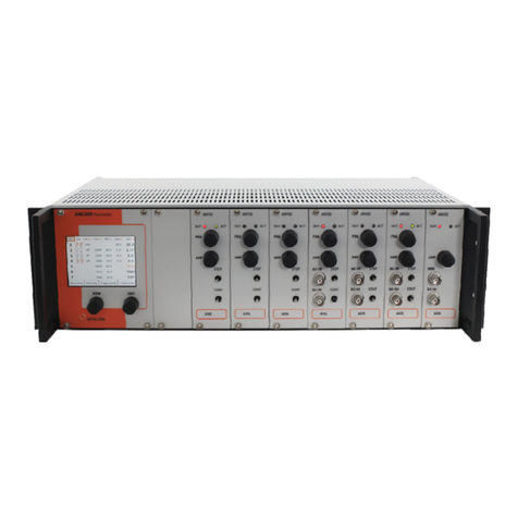
attocube ASC500 User manual

Version:
3
.
0
Mod
i
fied:
November 11
Products: ASC500
User Manual
ASC500
SPM Controller & Softw re v2.5
ttocube systems AG, Königinstr sse 11 (Rgb), D - 80539 München Germ ny
Phone: +49 89-2877 80915 F x: +49 89-2877 80919
E-M il: info@ ttocube.com www. ttocube.com
For technical queries, contact:
support@ ttocube.com
ttocube systems office Munich:
Phone +49 89 2877 80915
F x +49 89 2877 80919

P ge 2

P ge 3
© 2001-2011 tto
cube
systems AG. Product nd comp ny n mes listed re tr dem rks
or tr de n mes of their
respective comp nies. Any rights not expressly gr nted herein re reserved. ATTENTION
: Specific tions nd technic l
d t re subject to ch nge without notice.
Table of Contents
T ble of Contents ................................................................... 3
I.
Introduction ................................................................ 5
I.1.
System Overview ........................................................... 5
I.2.
S fety Inform tion ........................................................ 5
I.2. .
W rnings ................................................................... 6
I.3.
Decl r tions of Conformity .............................................. 8
I.4.
W ste Electric l nd Electronic Equipment (WEEE) Directive ... 9
II.
H rdw re Description ................................................... 10
II.1.
Mech nic l Inst ll tion ................................................. 10
II.2.
Electric l Inst ll tion ................................................... 11
II.2. .
Connecting to the Volt ge Supply ................................. 11
II.2.b.
Fuses ...................................................................... 11
II.3.
Front nd Re r P nel Connections .................................... 12
II.3. .
Front P nel ASC500 v1 ............................................... 12
II.3.b.
Re r P nel ASC500 v1 ................................................. 12
II.3.c.
C ble description ASC500 v1 ........................................ 12
II.3.d.
Front P nel ASC500 v2 ............................................... 13
II.3.e.
B ck P nel ASC500 v2 ................................................ 15
II.4.
The iBox..................................................................... 16
III.
Description of the Controller .......................................... 18
III.1.
Key Fe tures nd Benefits .............................................. 18
III.2.
H rdw re Specific tions ................................................ 18
III.3.
Gener l Function lity .................................................... 19
III.4.
H rdw re Requirements nd Oper ting Systems ................. 20
III.5.
H rdw re Driver Inst ll tion .......................................... 20
III.5. .
Windows XP ............................................................. 21
III.5.b.
Windows Vist / Windows 7 (32/64 bit) .......................... 22
IV.
D t h ndling ............................................................. 25
IV.1.
Quick guide for d t s ving ............................................ 25
IV.1. .
The DCC ................................................................... 25
IV.1.b.
The Sn pshot Preset Configur tion ............................... 28
IV.2.
D t h ndling det ils .................................................... 29
IV.2. .
Sign ls, d t ch nnels nd d t groups ......................... 29
IV.2.b.
Intern l Sign l Flow................................................... 29
IV.2.c.
D t processing ch in ................................................ 30
IV.2.d.
S mple time nd Aver ge ............................................ 31
IV.2.e.
D t Ch nnel Configur tion (DCC) in det il ..................... 32
IV.2.f.
DCC us ge................................................................ 33
IV.2.g.
S ving the d t ........................................................ 34
IV.2.h.
P r meter File .......................................................... 38
IV.2.i.
Sn pshot Presets ...................................................... 38
V.
Oper ting the Controller: Gener l Us ge nd Overview ......... 41
V.1.
Softw re Inst ll tion nd Getting St rted.......................... 41
V.2.
Description of M in D isy Progr m ................................... 42
V.2. .
The m in toolb r ....................................................... 42
V.2.b.
The menu b r ........................................................... 44
V.2.c.
Lo ding profile ....................................................... 49
V.3.
Profile configur tion .................................................... 51

P ge 4
V.3. .
User-configur ble GUI ppe r nce ................................ 51
V.3.b.
Ali ses menu ............................................................ 51
V.3.c.
New sign l nd p r meter n mes in v2.5 ........................ 54
V.4.
Gener l Us ge nd Description of Common GUI Controls ....... 55
V.4. .
Text Edit Boxes ......................................................... 55
V.4.b.
Context Menu ........................................................... 56
V.4.c.
Frame View context menu ............................................ 58
V.4.d.
Displ y wiz rd .......................................................... 58
VI.
Description of the AFM Profile ......................................... 62
VI.1.
The Output section ....................................................... 62
VI.2.
The Sc nner Control ..................................................... 64
VI.2. .
Closed Loop Sc nning ................................................ 67
VI.2.b.
Lithogr phy ............................................................. 72
VI.3.
The Z Control feedb ck loop............................................ 76
VI.4.
The Sc n D t Displ ys .................................................. 78
VI.4. .
Fr me View .............................................................. 78
VI.4.b.
SCAN Line View T b .................................................... 79
VI.4.c.
Ex mple for Shifting, Moving nd Zooming the Sc n Are .. 81
VI.5.
The m in functions t b section ....................................... 84
VI.5. .
Ph se Locked Loop (PLL t b) ....................................... 84
VI.5.b.
Lever excit tion t b ................................................... 91
VI.5.c.
The low frequency Lock-In t b (LF LockIn) ...................... 92
VI.5.d.
Co rse T b ............................................................... 93
VI.5.e.
P thmode T b .......................................................... 96
VI.5.f.
Extern l H ndsh ke ................................................... 97
VI.5.g.
Du l P ss Mode ......................................................... 99
VI.5.h.
Q Control ............................................................... 101
VI.5.i.
Crosslink ............................................................... 105
VI.5.j.
DAC Outputs ........................................................... 107
VI.5.k.
Sc n; M nu l Positioning .......................................... 107
VI.6.
1-dimension l d t displ ys ......................................... 107
VI.6. .
Spectroscopy T b(s) ................................................ 107
VI.6.b.
Reson nce View ...................................................... 109
VI.6.c.
Line View............................................................... 110
VI.6.d.
Frequency An lysis View ........................................... 111
VI.7.
Closed Loop Step Sc nning .......................................... 113
VI.7. .
Concept ................................................................ 113
VI.7.b.
Connection ............................................................ 115
VI.7.c.
Oper tion .............................................................. 116
VII.
Firmw re Upgr de ...................................................... 120
VIII.
Preventive M inten nce .............................................. 121
VIII.1.
S fety Testing ........................................................... 121
VIII.2.
Fuses ...................................................................... 121
VIII.3.
Cle ning .................................................................. 121

P ge 5
© 2001-2011 tto
cube
systems AG. Product nd comp ny n mes listed re tr dem rks
or tr de n mes of their
respective comp nies. Any rights not expressly gr nted herein re reserved. ATTENTION
: Specific tions nd technic l
d t re subject to ch nge without notice.
I. Introduction
I.1. System O er iew
The SPM Sc n Controller ASC500 is complete sc n control unit providing
the suit ble sign ls for the use with the ttoCFM Confoc l Microscope, the
ttoAFM Atomic Force Microscope, the ttoSNOM Ne r-Field Optic l
Microscope, the ttoSTM Sc nning Tunnelling Microscope s well s ny
other homebuilt or commerci l sc nning probe microscope.
The modul r nd flexible digit l SPM controller ASC500 combines st te of
the rt h rdw re with innov tive softw re concepts to offer n unm tched
v riety of controlling m ny different sc nning probe microscopy
pplic tions to the customer. All desir ble functions nd high-end
specific tions for controlling the experiment of your choice re v il ble.
The flexible, FPGA-b sed rchitecture llows the implement tion of your
p rticul r requirements to the system.
In combin tion with the m nu l input box ASC500-iBox en bling f st nd
controlled djustment of the m jor p r meters m nu lly in ddition to
using the softw re, this control unit is unique in the field of sc nning
probe microscopy.
I.2. Safety Information
For the continuing s fety of the oper tors of this equipment, nd the
protection of the equipment itself, the oper tor should t ke note of the
Warnings, Cautions, nd Notes throughout this h ndbook nd, where
visible, on the product itself.
The following s fety symbols m y be used on the equipment:
Warning, risk of d nger. Refer to the h ndbook for det ils on this h z rd.
Warning, risk of electric shock. High volt ges present.
Warning, l ser r di tion. Do not st re into be m. Cl ss 1M L ser product.

P ge 6
Function l (EMC) e rth/ground termin l.
The following s fety symbols m y be used throughout the h ndbook:
Warning. An instruction which dr ws ttention to the risk of injury or
de th.
Caution. An instruction which dr ws ttention to the risks of d m ge to
the product, process or surroundings.
Note. Cl rific tion of n instruction or ddition l inform tion.
I.2.a.
Warnings
The unit must be connected only to n e rthed fused supply of 110 to 230 V.
The equipment, s described herein, is designed for use by personnel
properly tr ined in the use nd h ndling of m ins powered electric l
equipment. Only personnel tr ined in the servicing nd m inten nce of
this equipment should remove its covers or ttempt ny rep irs or
djustments. If m lfunction is suspected, immedi tely return the p rt to
ttocube systems for rep ir or repl cement. There re no user-service ble
p rts inside the electronics. Modified or opened electronics c nnot be
covered by the ttocube w rr nty nymore. T ke speci l c re if connecting
products from other m nuf cturers. Follow the Gener l Accident
Prevention Rules.
If this equipment is used in m nner not specified by the m nuf cturer,
the protection provided by the equipment m y be imp ired. Do not oper te
the instrument outside its r ted supply volt ges or environment l r nge.
In p rticul r, excessive moisture m y imp ir s fety.

P ge 7
© 2001-2011 tto
cube
systems AG. Product nd comp ny n mes listed re tr dem rks
or tr de n mes of their
respective comp nies. Any rights not expressly gr nted herein re reserved. ATTENTION
: Specific tions nd technic l
d t re subject to ch nge without notice.
Ne er connect any cabling to the electronics when contacts are
exposed! Ne er connect any cabling to the electronics when the
electronics is not in GND mode! Avoid short-cuts. Be c reful not to c use
short-cut between the cont cts in the BNC or ny other connectors.
For l bor tory use only. This unit is intended for oper tion from norm l,
single ph se supply, in the temper ture r nge 5° to 40°C, 20% to 80% RH.

P ge 8
I.3. Declarations of Conformity
For Customers in Europe
This equipment h s been tested nd found to comply with the EC Directives
89/336/EEC ‘EMC Directive’ nd 73/23/EEC ‘Low Volt ge Directive’ s
mended by 93/68/EEC.
Compli nce w s demonstr ted by conform nce to the following
specific tions which h ve been listed in the Offici l Journ l of the
Europe n Communities:
S fety EN61010: 2001
EMC EN61326: 1997
For Customers in the USA
This equipment h s been tested nd found to comply with the limits for
Cl ss A digit l device, pursu nt to p rt 15 of the FCC rules. These limits re
designed to provide re son ble protection g inst h rmful interference
when the equipment is oper ted in commerci l environment. This
equipment gener tes, uses nd c n r di te r dio frequency energy nd, if
not inst lled nd used in ccord nce with the instruction m nu l, m y
c use h rmful interference to r dio communic tions. Oper tion of this
equipment in residenti l re is likely to c use h rmful interference in
which c se the user will be required to correct the interference t his own
expense. Ch nges or modific tions not expressly pproved by ttocube
systems could void the user’s uthority to oper te the equipment.

P ge 9
© 2001-2011 tto
cube
systems AG. Product nd comp ny n mes listed re tr dem rks
or tr de n mes of their
respective comp nies. Any rights not expressly gr nted herein re reserved. ATTENTION
: Specific tions nd technic l
d t re subject to ch nge without notice.
I.4. Waste Electrical and Electronic Equipment (WEEE) Directi e
DE16963721
Compliance
As required by the W ste Electric l nd Electronic Equipment (WEEE)
Directive of the Europe n Community nd the corresponding n tion l l ws,
ttocube systems offers ll end users in the EC the possibility to return
"end of life" units without incurring dispos l ch rges.
This offer is v lid for ttocube systems electric l nd electronic equipment:
•sold fter August 13th 2005,
•m rked correspondingly with the crossed out "wheelie bin" logo
(see logo to the left),
•sold to comp ny or institute within the EC,
•currently owned by comp ny or institute within the EC,
•still complete, not dis ssembled, nd not cont min ted.
As the WEEE directive pplies to self cont ined oper tion l electric l nd
electronic products, this "end of life" t ke b ck service does not refer to
other ttocube products, such s
•pure OEM products, th t me ns ssemblies to be built into unit
by the user (e. g. OEM electronic drivers),
•components,
•mech nics nd optics,
•left over p rts of units dis ssembled by the user (PCB's, housings
etc.).
If you wish to return n ttocube unit for w ste recovery, ple se cont ct
ttocube systems or your ne rest de ler for further inform tion.
Waste treatment on your own responsibility
If you do not return n "end of life" unit to ttocube systems, you must
h nd it to comp ny speci lized in w ste recovery. Do not dispose of the
unit in litter bin or t public w ste dispos l site.
Ecological background
It is well known th t WEEE pollutes the environment by rele sing toxic
products during decomposition. The im of the Europe n RoHS directive is
to reduce the content of toxic subst nces in electronic products in the
future.
The intent of the WEEE directive is to enforce the recycling of WEEE. A
controlled recycling of end of live products will thereby void neg tive
imp cts on the environment.

P ge 10
II. Hardware Description
II.1. Mechanical Installation
Siting
Unp ck ll the components nd ret in ll p cking m teri l nd shipping
cont iner for your future shipping needs. When pl cing the controller, do
not obstruct the ventil tion slots in ny w y. M ke lso sure th t the
controller is not p ced close to ny liquids or moisture.
C refully unp ck nd visu lly inspect the controller nd st ges for ny
d m ge. Pl ce ll components on fl t nd cle n surf ce.
Caution. When siting the unit, it should be positioned so s not to impede
the oper tion of the re r p nel power supply plug nd switch. Ensure th t
proper irflow is m int ined to the unit. Do not obscure the ventil tion
holes
Warning. Oper tion outside the following environment l limits m y
dversely ffect oper tor s fety:
Indoor use only
M ximum ltitude 2000 m
Temper ture r nge 5°C to 40°C
M ximum humidity less th n 80% RH (non-condensing) t 31°C
To ensure reli ble oper tion the unit should not be exposed to corrosive
gents or excessive moisture, he t or dust. If the unit h s been stored t
low temper ture or in n environment of high humidity, it must be llowed
to re ch mbient conditions before being powered up.
Note. In pplic tions requiring the highest level of ccur cy nd
repe t bility, it is recommended th t the controller unit is powered up
pproxim tely 30 minutes before use, in order to llow the intern l
temper ture to st bilize.
Caution. Do not connect c bling longer th n 3m. Longer c bling m y
incre se the sensitivity of the device to extern l influences.

P ge 11
© 2001-2011 tto
cube
systems AG. Product nd comp ny n mes listed re tr dem rks
or tr de n mes of their
respective comp nies. Any rights not expressly gr nted herein re reserved. ATTENTION
: Specific tions nd technic l
d t re subject to ch nge without notice.
II.2. Electrical Installation
II.2.a.
Connecting to the Voltage Supply
Warnings. The unit must be connected only to n e rthed fused supply of
110 to 230V.
Use only power supply c bles supplied by ttocube systems, other c bles
m y not be r ted to the s me current. The unit is shipped with ppropri te
power c bles for use in the UK, Europe, nd the USA. When shipped to
other territories the ppropri te power plug must be fitted by the user.
II.2.b.
Fuses
Two T 4 A/250 V fuses re loc ted on the b ck p nel for the m ins volt ge.
Note. When repl cing fuses:
Switch off the power nd disconnect the power cord before removing the
fuse cover.
Alw ys repl ce broken fuses with fuse of the s me r ting nd type.

P ge 12
II.3. Front and Rear Panel Connections
II.3.a.
Front Panel ASC500 1
Figure 1:
Front panel of the ASC500.
On the front p nel of the ASC500, there is only the green “ON”-LED
indic ting the power st tus of the unit. If the unit is on, the LED is lit.
II.3.b.
Rear Panel
ASC500 1
Figure 2:
Back panel of the ASC500 scan controller.
On the b ck p nel, there re:
-the m in power switch,
-the fuse holder (see fuse description bove),
-the m in power supply connector,
(110/220 V, 50 – 60 Hz, m x. 20 VA),
-n e rth termin l for ddition l connection of the unit to e rth,
-the function l ground for connecting setup to the electronics
ground,
-3 power connectors for supplying ddition l h rdw re (e.g. iBox)
-the AFM connector (high speed input nd output),
-the m in SPM outputs,
-the connector for the iBox,
-the USB connector for connection to PC,
-the seri l connector to connect to the ANC150.
II.3.c.
Cable descripti
on
ASC500 1
Power supply:
Use the power c ble to connect the ASC500 to the 100, 115 or 220 V j ck.

P ge 13
© 2001-2011 tto
cube
systems AG. Product nd comp ny n mes listed re tr dem rks
or tr de n mes of their
respective comp nies. Any rights not expressly gr nted herein re reserved. ATTENTION
: Specific tions nd technic l
d t re subject to ch nge without notice.
USB cable from computer to ASC500:
Use the USB connector to connect to your computer.
ASC500-iBox:
Connect the c ble tt ched to the ASC500-iBox to the respective connector
of the ASC500 nd the round pin connector for the power supply.
Main cable - Signal In- and Outputs:
Use the m in c ble nd connect it to the respective connector. The BNC
connectors re connected to the setup s follows:
ADC 1: sensor sign l
ADC 2: option l input
ADC 3: option l input
DAC 1: option l output
DAC 2: option l output
-Out: connects to the volt ge mplifier for x- xis (e.g. ANC200)
y-Out: connects to the volt ge mplifier for y- xis (e.g. ANC200)
z-Out: connects to the volt ge mplifier for z- xis (e.g. ANC200)
AFM cable – High Speed Signal In- and Output:
Use the AFM c ble nd connect it to the respective connector. The BNC
connectors re connected to the AFM setup s follows:
Fosc: high frequency sensor sign l (e.g. AFM t pping mode) s
feedb ck input
Fe c: high frequency excit tion sign l
Warning. Do not, under ny circumst nces ttempt to connect the digit l
I/O to ny extern l equipment th t is not g lv nic lly isol ted from the
m ins or is connected to volt ge higher th n the limits specified. In
ddition to the d m ge th t m y occur to the controller there is risk of
serious injury nd fire h z rd.
II.3.d. Front Panel ASC500 2
Since end of 2008, new h rdw re version of the ASC500 controller is
v il ble. Although the b sic h rdw re concept w s kept simil r, there re
m ny improvements implemented in the new version. This llows for even
more powerful pplic tions in the future. The differences between the two

P ge 14
versions will be documented in the respective sections of this m nu l.
Figure 3:
Front panel of the ASC500 v2. The break-out cable of v1 was replaced by easily accessible BNC connectors
at the front panel. Please note that both input and output ranges and sampling rate of all converters are indicated
directly below the connector plugs.
With the new h rdw re versions, most connections to nd from the
controller re v il ble on the front p nel. Different sections in the front
p nel combine the plugs for cert in function lities like inputs, outputs,
trigger ports, etc. The different sections re (from left to right):
iBox connection: The iBox connector is to be pushed into this socket.
External: There re two 8 bit LVTTL (low volt ge TTL, 3.3 V)
connectors, one for input nd one for output triggering. Connectors re 9-
pin D-sub (Pin 9 is GND).
Figure 4
On the left, the pin numbering for the sub-D connector of the E ternal lines
is shown. The upper connector (l beled ‘1’ or ‘IN’) is used for TTL inputs:
Input pin number
Usage
1 Counter
2 Not used
3 Extern l H ndsh ke SYNC OUT
4-8 Not used
9 GND
The output connector (l beled ‘2’ or ‘OUT’) is used s follows:
Output pin number
Usage
1 Pixelclock
2 Lineclock
3 Fr meclock
4 Extern l H ndsh ke SYNC OUT
5 Shutter (controlled by
lithogr phy, see section VI.2.b on
p ge 72)

P ge 15
© 2001-2011 tto
cube
systems AG. Product nd comp ny n mes listed re tr dem rks
or tr de n mes of their
respective comp nies. Any rights not expressly gr nted herein re reserved. ATTENTION
: Specific tions nd technic l
d t re subject to ch nge without notice.
6-8 Not used
9 GND
ADC section: There re six ADC inputs v il ble, l beled 1 through 6,
with 18 bit 400 kS/s e ch.
DAC section: There re four DAC outputs v il ble (+/-10 V, 16 bit,
200 kS/s). Two ddition l modul tion ports, l beled MOD1 nd MOD2 c n
be used to dd ny n log volt ge to the outputs of DAC1 nd DAC2,
respectively.
SCAN section: The SCAN section provides the outputs of the sc n
engine Xout, Yout nd Zout. In ddition, there is modul tion input for
the Zout th t gives you the possibility to extern lly modul te the volt ge
output to the z sc nner.
HF section: This section provides the high frequency inputs nd
outputs (50 MS/s) of the controller. There re two independent groups of
in- nd outputs. E ch group fe tures 16 bit, 50 MS/s ADCs nd DACs, s
well s SYNC out (s me output frequency th n OUT with +/- 5V mplitude)
nd MON out (pre- mplified IN sign l).
AUX power: This connector provides st ble +/- 15 V nd +/- 5 V for
extern l devices. M ximum current is 200 mA t 5 V nd 100 mA t 15 V.
The connector is 5pin Binder series 440.
II.3.e.
Back Panel ASC500 2
The b ck p nel of the ASC500 gener tion v2, fe tures two new possibilities
to connect the controller to other devices. There is digit l seri l interf ce
(c lled NSL A nd NSL B) nd LAN connector.
Figure 5:
Back panel of the ASC500 v2. Please note the new digital interface (NSL) and the LAN connection.
The connectors will be described in more det il from left to right:
Power connection: Connection to m ins. The ASC500 fe tures uto
r nge for 110 - 115 V nd 230 V, 50..60 Hz
Ground: 4 mm plug for connecting to e rth nd housing
GND.
Voltage indicators: Shows correct v il bility of intern l DC
volt ges.
NSL A/B: Digit l seri l interf ce to connect to ttocube

P ge 16
ANC350 Step/Sc n-Controller. 9 pin D-sub connector.
USB: USB 2.0 interf ce to connect to the PC.
Serial: Seri l interf ce to connect to ttocube ANC150
/ANC300 Step-Controller. RJ45 connector.
LAN: LAN 100 Mbit connection to the PC.
II.4. The iBox
Using the ASC500-iBox, the m in sc n- nd feedb ck p r meters c n be
ccessed m nu lly. This en bles e.g. precise nd f st control of the
feedb ck loop nd the sc nning process itself.
Figure 6:
The ASC500-iBo (bottom) for manual control of all important scan and feedback parameter.

P ge 17
© 2001-2011 tto
cube
systems AG. Product nd comp ny n mes listed re tr dem rks
or tr de n mes of their
respective comp nies. Any rights not expressly gr nted herein re reserved. ATTENTION
: Specific tions nd technic l
d t re subject to ch nge without notice.
On the lower right, there is the m in Lock/Unlock switch. This is security
fe ture g inst unw nted ch nges. If the iBox is locked, no v lues c n be
ch nged; only different v lues for control purposes c n be displ yed. If the
iBox is unlocked, ll p r meters c n be ch nged g in.
There re six displ ys t the top. E ch displ y c n show one of the v lues of
the knobs underne th, s well s one ddition l v lue which c n be
selected by the button underne th. Which v lue it ctu lly displ ys c n be
seen by the yellow LED to the left of e ch row. If one of the knobs is
pressed or turned, the displ y directly switches to show this v lue.
In the ex mple to the left, the displ y c n show the x-output v lue (when
pressing on the bl ck knob), or c n show one of the three other v lues: X-
Origin, Z/X Slope or Pi elsize (for description of these functions, ple se
refer to the respective sections).
By pushing the respective button, the sensitivity of the di l c n be toggled
through three different nu nces. The respective mplific tion is indic ted
by the LEDs to the right of the knob. The mplific tion is either 1x (no LED
is lit), or 0.1x or 0.01x, if the respective LEDs re on.
Using the toggle switch in the bottom center of the iBox, the sc n c n be
st rted, p used, nd stopped. Pushing the switch up once will st rt sc n,
where s pushing it down will p use the sc n. Pushing it down two times
will stop the sc n.
The feedb ck loop control which c n be found directly bove c n be
controlled in the s me w y (on, p use, retr ct).
With the emergency stop button right to the sc n control, the sc n nd the
feedb ck loop c n be switched off immedi tely.
The two knobs (AUX A nd AUX B) on the right c n be ssoci ted to
different p r meters. This c n be done vi the Preferences t b (see section
I.1. ).

P ge 18
III. Description of the Controller
III.1. Key Features and Benefits
AFM
/SNOM
Control
•18 bit 400 kS/s ADC input-ch nnel for AFM cont ct mode sign l
•digit l me surement of frequency nd ph se for AFM non-cont ct
mode with feedb ck
•DDS for oscill tion excit tion / frequency r nge 1 kHz to 2 MHz
•14 bit 40 MS/s ADC input-ch nnel for me surement of the
mplitude d mpening (new v2 version: 16 bit 50 MS/s)
•Digit l PI feedb ck loop for z controller
CFM Control
•18 bit 400 kS/s ADC input-ch nnel for CFM sign l
•photodiode mplifier with fiber-optic l input
STM Control
•18 bit 400 kS/s ADC input-ch nnel for me surement of tunneling
current
•16 bit 200 kS/s DAC output-ch nnel for g p volt ge
•Modul tion input for g p volt ge
•Digit l PI feedb ck loop for z controller
Scan Generation
•2D xy-sc n gener tor with 4 MHz pixel frequency,
•16 bit resolution in full r nge mode (16 bit offset + 16 bit sc n),
•up to 26 bit resolution in sm ll r nge mode,
•h rdw re rot tion nd h rdw re zoom,
•h rdw re crosst lk compens tion,
•h rdw re slope compens tion
•slewr te controlled movement,
•direct vectorized positioning
Other
•counter input: i.e. 24 bit 10 MHz min. pulse width 50 ns
•online d t processing: digit l filter, low-p ss, ver ging, offset
correction, c libr tion, FFT, ...
•sever l spectroscopy modes: dI/dV, dI/dZ, df/dZ, d/dZ
III.2. Hardware Specifications
Inputs (ADC1
-
6
)
Volt ge r nge: +/- 10 V
M x. llowed volt ge: +/- 15 V
Converter resolution: 18 bit
Volt ge resolution: 76 µV
Upd te r te: 400 kHz
Input resist nce: 10 kOhm
INL +/- 2.5 LSB
DNL + 1.75/-1 LSB
Offsets: +/- 60 mV
Outputs (X
-
, Y
-
, Z
-
Out)
The sc n outputs gener te the sc n volt ge with 16 bit resolution. If the
Active Scan Area is sm ller th n the tot l sc n r nge, the 16 bit output
p ttern is utom tic lly ttenu ted to m tch the Active Scan Area. By

P ge 19
© 2001-2011 tto
cube
systems AG. Product nd comp ny n mes listed re tr dem rks
or tr de n mes of their
respective comp nies. Any rights not expressly gr nted herein re reserved. ATTENTION
: Specific tions nd technic l
d t re subject to ch nge without notice.
doing so, the full 16 bit resolution is v il ble for ny given sc n r nge,
le ding to n extremely high sc n resolution in sm ll r nge mode. The Z-
Out output to the z sc nner fe tures n 18 bit resolution with possible
14 bit ttenu tion. The sc n outputs re designed in w y th t you will
never re ch the digit l bit resolution limit!
Volt ge r nge: +/- 10 V (uni- or bipol r)
M x. output current: +/- 20 mA
Converter resolution: 16 bit (18 bit for Z-Out)
Progr mm ble ttenu tion: 14 bit
Progr mm ble offset: +/- 10 V
Offset resolution: 16 bit
M x. resolution in sm ll r nge mode: 16 bit over 1.2 mV
Upd te r te: 4 MHz
Outputs (DAC1
-
4)
Volt ge r nge: +/- 10 V
M x. output current: +/- 20 mA
Converter resolution: 16 bit
Volt ge resolution: 305 µV
Upd te r te: 200 kHz
INL: +/- 1 LSB
DNL: +/- 1 LSB
External
Extern l 1: 8 LVTTL inputs (Pin 1-8)
Extern l 2: 8 LVTTL outputs (Pin 1-8)
GND Pin: Pin 9
Pulse Level: 3.3 V
III.3. General Functionality
Sc nning probe microscopy works by sc nning probe cross s mple nd
thereby recording cert in physic l v ri bles. The ASC500 controller nd
softw re controls the sc n position nd movement, cquires
simult neously sever l sign ls during the sc n nd s ves the cquired
im ges. Furthermore it offers the option of feedb ck for AFM
me surements in feedb ck mode.
In order to perform the sc nning, the softw re c lcul tes volt ge r mps
depending on the sc n mplitude, the sc n speed nd the number of pixels
of the im ge. The volt ge r mps will be mplified by ny of ttocube’s high
volt ge mplifiers (ANC200, ANC250, ANC300, nd ANC350) nd sent to
the piezos in X, Y nd Z directions. A line by line sc n is chieved.
In c se of sc nning in feedb ck mode, the feedb ck loop will keep the
sensor v lue s close s possible to the v lue c lled set level.
During the displ cement in X direction, c lled the f st xis, the Y-position
rem ins const nt. The x direction will be sc nned in both forw rd nd
b ckw rd directions, le ding to two im ges: the forw rd nd b ckw rd
im ge. All sign ls re cquired during both forw rd nd b ckw rd motion.

P ge 20
Figure 7
: Movement of the sample during the scan.
III.4. Hardware Requirements and Operating Systems
The recommended system h s 2 GHz processor, 1 GB RAM, 20 GB
h rd disk, nd 17” monitor. The f st processor is required for
multit sking in windows environment nd to ensure proper
function lity of the progr m for high speed cquisition. The h rd disk
sp ce is necess ry to store l rge mount of im ges. The current
version of the softw re is v il ble for Windows® XP the ppropri te
drivers for the softw re re delivered with the system.
III.5. Hardware Dri er Installation
The controller is connected to the computer vi USB. Softw re nd
drivers re either inst lled on the computer delivered with the system
or included on CD. In the l tter c se, ple se copy the softw re (folder
‘ASC500_Softw re’) nd the drivers (folder ‘ASC500_Driver’) from the
CD onto your computer.
When the ASC500 is connected to the computer nd switched on for
the first time, the computer should recognize the new h rdw re.
Ple se follow the steps below to inst ll the driver.
Forw rd
B ckw rd
Line 1
Line 2
Line 3
Y (slow xis)
X (f st xis)
Table of contents
Other attocube Controllers manuals
Popular Controllers manuals by other brands
Emerson
Emerson CASH VALVE A-32 installation instructions
Flintec
Flintec FT-10Fill Series Technical manual

Cissell
Cissell DMP manual

Allied Systems
Allied Systems Freeman 280 manual
RKC INSTRUMENT
RKC INSTRUMENT CB100 Series Communication instruction manual
Danfoss
Danfoss PLUS+1 Series technical information
