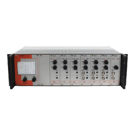
attocube ECC100 User manual

Version:
2.
8
Modified:
October 2018
Products:
ECC100
, DAISY Soft are
ECC100
ECS-Positioner Controller
User Manual

Page 2
Table of Contents
Table of Contents ......................................................................... 2
Safety Information ....................................................................... 1
Important Warnings – Read this Section First! .................................... 2
Declarations of Conformity ............................................................. 3
Waste Electrical and Electronic Equipment (WEEE) Directive .................. 4
I. System Overvie .................................................................... 5
II. Setup Procedure .................................................................... 7
II.1. Mechanical Installation .................................................. 7
II.2. Electrical Installation .................................................... 8
II.2.1. Rear Panel Connections ................................................ 8
II.2.2. Positioner Control Cables.............................................. 9
II.2.3. Ho to connect a positioner: ....................................... 10
II.2.4. Pin Assignment of the Axis Outputs ............................... 11
II.2.5. Pin Assignment of the GPIO-port .................................. 12
III. Soft are ............................................................................. 14
III.1. Hard are Requirements ................................................ 14
III.2. Operating System ......................................................... 14
III.3. Hard are Driver Installation .......................................... 14
III.4. DAISY Soft are Installation............................................ 16
IV. Graphical User Interface (GUI) ................................................. 17
IV.1. Starting the System (DAISY) ........................................... 17
IV.1.1. ECC Settings ............................................................ 18
IV.1.2. ECC Ethernet settings ................................................ 22
IV.1.3. Controlling Positioners ith the GUI ............................. 23
IV.2. Connect to a specific ECC100 ith the DAISY ...................... 27
IV.2.1. Startup ................................................................... 27
IV.2.2. Configuring ECC ID settings ......................................... 27
IV.3. Connecting t o or more ECCs to one PC ............................. 27
IV.4. Upgrading .................................................................. 28
IV.5. Installing ne positioner profiles .................................... 29
IV.6. Closing the GUI and s itching off the ECC100 ..................... 29
V. Firm are update ................................................................... 30
VI. DLL .................................................................................... 31
VI.1. LabVie Drivers ........................................................... 31

Page 1
© 2001-2018
attocube systems AG. Product and company names listed are trademarks or trade names of their respective
companies. Any rights not expressly granted herein are reserved. ATTENTION
: Specifications and technical data are
subject to change ithout notice.
Safety Information
For the continuing safety of the operator of this equipment and the
protection of the equipment itself, the operator should take notice of the
Warnings, Cautions, and Notes throughout this manual and - here
applicable - on the device itself.
The follo ing safety symbols are used in this manual:
Caution. Hot surface. May cause injury hen touched.
Caution. An instruction hich dra s attention to the risks of damage to the
device, process, or surrounding.
Warning. Risk of electric shock. High voltages present.
Warning. Laser radiation. Do not stare into the beam. Class 1M Laser
product.
Caution. Electro-statically sensitive device. Equipment may get damaged if
touched by personnel not grounded. Only touch ith earthed ristband
attached or other ise connected to ground.
Note. Clarification of an instruction or additional information.
Functional (EMC) earth/ground terminal.

Page 2
Important Warnings – ead this Section First!
The unit described in this manual must only be connected to a grounded
and fused line voltage supply of 100, 115, or 230V, respectively.
Warning. The equipment, as described herein, is designed to be used by
persons properly trained in the use and handling of mains po ered
electrical equipment. Only persons trained in servicing and maintenance of
this equipment should remove its protective covers or attempt any repair or
adjustments.
If malfunction of the controller is suspected, please immediately contact
attocube systems for repair or replacement. Take special care if you connect
products of other manufacturers to the controller. Follo the General
Accident Prevention Rules.
Note. Modified or opened electronics are no longer covered in terms of
attocube’s arranty.
Warning. Do not operate the instrument outside its dedicated supply
voltage or environmental range. If this equipment is used in a manner not
specified by the manufacturer, the protection provided by the equipment
can be impaired. In particular, excessive moisture can impair safety.
Warning. Never connect any cabling to the electronics when the outputs
are enabled! The scan piezo elements in positioner units are high voltage
components and can cause serious injuries.
Caution. Avoid short-circuits. Be careful not to create short-circuits
bet een the contacts in the Sub-D connector or any here in the cabling.
Note. There are no user serviceable parts inside the motor or the
controller.
Caution. For laboratory and industrial use only. This unit is intended for
operation in conjunction ith a normal, single phase supply, in a
temperature range of 5°C to 40°C, and a relative humidity of 20% to 80%.
Firmware update. Before updating the firm are of the ECC100 please
contact attocube systems for technical support. Unauthorized updates can
lead to a permanent malfunction and ill not be covered by attocube’s
arranty.

Page 3
© 2001-2018
attocube systems AG. Product and company names listed are trademarks or trade names of their respective
companies. Any rights not expressly granted herein are reserved. ATTENTION
: Specifications and technical data are
subject to change ithout notice.
Declarations of Conformity
For Customers in Europe
:
This equipment has been tested and found to comply ith the EC
Directives 89/336/EEC ‘EMC Directive’ and 73/23/EEC ‘Lo Voltage
Directive’ as amended by 93/68/EEC.
Compliance as demonstrated by conformance to the follo ing
specifications hich have been listed in the Official Journal of the
European Communities:
Safety EN61010: 2001
EMC EN61326: 1997
For Customers in the USA:
This equipment has been tested and found to comply ith the limits for
a Class A digital device, pursuant to part 15 of the FCC rules. These
limits are designed to provide reasonable protection against harmful
interference hen the equipment is operated in a commercial
environment. This equipment generates uses and can radiate radio
frequency energy and, if not installed and used in accordance ith the
instruction manual, may cause harmful interference to radio
communications. Operation of this equipment in a residential area is
likely to cause harmful interference in hich case the user ill be
required to correct the interference at his/her o n expense. Changes
or modifications not explicitly approved by attocube systems could
void the user’s authority to operate the equipment.

Page 4
Waste Electrical and Electronic Equipment (WEEE)
Directive
DE16963721
Compliance
As required by the Waste Electrical and Electronic Equipment (WEEE)
Directive of the European Community and the corresponding national
la s, attocube systems offers all end users ithin the European Union
(EU) the possibility to return “end of life” units ithout incurring disposal
charges.
This offer is valid for attocube systems electrical and electronic
equipment:
•sold after August 13th 2005,
•marked correspondingly ith the crossed out “ heelie bin” logo
(see logo to the left),
•sold to a company or institute ithin the EU,
•currently o ned by a company or institute ithin the EU,
•still complete, not disassembled, and not contaminated.
As the WEEE directive applies to self- contained operational electrical and
electronic products, this “end of life” take back service does not refer to
other attocube products, such as
•pure OEM products, that means assemblies to be built into a unit
by the user (e. g. OEM electronic drivers),
•components,
•mechanics and optics,
•left over parts of units disassembled by the user (PCB’s, housings
etc.).
If you ish to return an attocube unit for aste recovery, please contact
attocube systems or your nearest dealer for further information.
Waste treatment on your own responsibility
If you do not return an “end of life” unit to attocube systems, you must
hand it to a company specialized in aste recovery. Do not dispose of the
unit in a litter bin or at a public aste disposal site.
Ecological background
It is ell kno n that WEEE pollutes the environment by releasing toxic
products during decomposition. The aim of the European RoHS directive is
to reduce the content of toxic substances in electronic products in the
future.
The intent of the WEEE directive is to enforce the recycling of WEEE. A
controlled recycling of end of live products ill thereby avoid negative
impacts on the environment.

Page 5
© 2001-2018
attocube systems AG. Product and company names listed are trademarks or trade names of their respective
companies. Any rights not expressly granted herein are reserved. ATTENTION
: Specifications and technical data are
subject to change ithout notice.
I. System Overview
The ECC100 is a state-of-the-art motion controller, allo ing the
simultaneous operation of up to three positioners from attocube’s
industrial ECS Drive series. The positioners connected to the ECC100 can be
an arbitrary combination of encoded (/NUM) and open-loop positioners,
depending on the customer’s choice.
The ECC100 is designed to be operated remotely via a computer by using
the PC soft are interface “DAISY”. A basic version of DAISY is provided by
attocube systems by default, a fully-featured “PRO”-version of DAISY can
be purchased through attocube’s sales team. In addition to the PC soft are
interface, a *.DLL library is delivered ith each ECC100 unit, enabling
higher integration of the functionality of the motion controller into
customized soft are routines. For synchrotron applications, a /SYNC
option - consisting of physical Ethernet connectivity and EPICS driver set -
is available as an option.
With the ECC100, positioners of the ECS series can be driven in both open-
loop and closed-loop (only for /NUM encoded positioners) drive mode.
These t o modes are explained in the follo ing.
Open-loop positioning:
In this mode, all ECS positioners connected to the ECC100 motion
controller are operated ithout position feedback.
By setting appropriate piezo-drive voltages in the ECC100, the physical
step size of the positioner can be varied ithout any actual position
information. The speed of the motion of positioners is user-adjustable by
varying the step frequency bet een 1Hz and 5kHz. A frequency of 5kHz is
only available on one axis at any one time; frequencies up to 2kHz can be
handled on three axes simultaneously. Open-loop positioning is available
for all positioners of the ECS series.
Closed-loop positioning:
In this mode, encoded positioners connected to the ECC100 motion
controller are operated ith an active feedback loop on the position.
In contrast to the open-loop mode, the ECC100 allo s to set and control
the absolute position of targets (closed-loop positioning) ith a resolution
of 1nm for linear positioners and 1µ° for rotary positioners, respectively
(/NUM or /NUM+ encoder option). The closed-loop positioning is
especially valuable for those applications, here (i) no other physical
feedback on the target position is available, (ii) certain target positions
need to be frequently addressed, or (iii) accurate positioning is crucial.
Please refer to the specification sheets of the ECS positioners for further
information regarding motion specifications in closed-loop mode.

Page 6

Page 7
© 2001-2018
attocube systems AG. Product and company names listed are trademarks or trade names of their respective
companies. Any rights not expressly granted herein are reserved. ATTENTION
: Specifications and technical data are
subject to change ithout notice.
II. Setup Procedure
II.1. Mechanical Installation
Setting up
Please unpack the controller and the delivered positioning stages (if
applicable) carefully and inspect them for any damages. Place all
components on a flat and clean surface.
Caution. When setting up the ECC100 controller for the first use, it should
be positioned in such a ay that the operation of the po er supply plug is
not impeded. Ensure that proper airflo is maintained to the unit. Do not
obscure the ventilation slots.
Warning. Operation outside the follo ing environmental limits may
adversely affect the safety of the operator:
•Indoor use only
•Maximum altitude 2000 m
•Temperature range 5°C to 40°C
•Relative humidity less than 80% (non-condensing) at about 30°C
To ensure reliable operation, the unit should not be exposed to corrosive
agents or excessive moisture, heat or dust. If the unit has been stored at a
lo temperature or in an environment of high humidity, it must be allo ed
to reach ambient conditions before being po ered up.
Caution. For applications requiring the highest level of accuracy and
repeatability, it is recommended that the controller unit is po ered up
approximately 30 minutes before usage in order to allo the internal
temperature to stabilize.
Caution. Do not connect any cable longer than 5m. Longer cables may
increase the sensitivity of the device to external influences.
Caution. Only use control cables supplied by attocube systems. Other
cables may affect the sensitivity of the device to external influences or may
cause errors.
Caution. Vacuum feedthroughs from attocube come ith a complete set of
cabling and an adaptor for testing ithout actually using the feedthrough.
This feedthrough al ays belongs in bet een the vacuum cabling and the
external cable. Reversing the direction of the external cable ill damage
the built-in encoder (NUM or NUM+)!

Page 8
II.2. Electrical Installation
To start the ECC100 Motion Controller, please connect the controller to the
voltage supply and press the round po er button on the front panel.
Warning. The unit must be connected to a grounded and fused line voltage
supply ith a voltage ranging from 95 V to 250 V and a line frequency
ranging from 50 Hz to 60 Hz.
Warning. Only use po er supply cables supplied by attocube systems,
other cables may not be rated to the same current. The unit is shipped ith
appropriate po er cables for usage in the UK, Europe, and the USA. When
shipped to other territories, the appropriate po er plug has to be provided
by the user.
II.2.1. ear Panel Connections
On the rear panel, there are follo ing connections:
01 main po er supply connector ith main fuse
(95 V to 250 V, 50 Hz – 60 Hz, max. 50 VA)
02 Ethernet port (optional)
03 Serial port (for internal use only)
04 USB port for connection to a computer
05 GPIO connector (Sub-D, 26-pin)
06 Positioner connectors: Sub-D 15-pin connectors
(max. 45 V, 4.5 A) three axes
01 02 03 04 05 06

Page 9
© 2001-2018
attocube systems AG. Product and company names listed are trademarks or trade names of their respective
companies. Any rights not expressly granted herein are reserved. ATTENTION
: Specifications and technical data are
subject to change ithout notice.
II.2.2. Positioner Control Cables
Positioner control cables are used to connect the ECC100 electronics to any
of attocube’s ECS-positioners. attocube provides these cables along ith
each delivered axis by default.
oom Temperature ( T)
Vacuum (HV / UHV)
Caution. Avoid short-circuits. Be careful not to cause short-circuits
bet een the contacts in the Sub-D connector or any here in the cabling.
Caution. Do not reverse the direction of the cable! As the cables don’t
follo a simple one to one configuration you might break the
optoelectronic sensor by applying high piezo voltages.

Page 10
II.2.3. How to connect a positioner:
Connecting positioners is simply done by connecting the 15-pin connector
of a positioner control cable to an axis socket and the other end to the
corresponding positioner (see the figure belo ).
Optional vacuum feedthrough:
In addition to all attocube positioning systems, specific vacuum
feedthroughs are optionally available. As an example, the image belo
depicts a feedthrough for a single /NUM-positioner. Vacuum feedthroughs
for multiple axes are also available. For more information please visit us at
http://attocube.com/nanoPOSITIONING/feedthroughs.htm or inquire at
sales@attocube.com .
With every feedthrough, an alternative adapter is delivered allo ing the
user to test the hole system ithout dismantling the original
feedthrough.
Caution. Do not reverse the direction of the cable! The adaptor should
al ays be placed in bet een the vacuum cabling delivered ith the
feedthrough and the external cable connected to the controller.
Vacuum feedthrough /NUM-positioner and alternative-adapter
Positioner Control
Cable
optional
Vacuum
Extension Cable
Vacuum
Feedthrough

Page 11
© 2001-2018
attocube systems AG. Product and company names listed are trademarks or trade names of their respective
companies. Any rights not expressly granted herein are reserved. ATTENTION
: Specifications and technical data are
subject to change ithout notice.
II.2.4. Pin Assignment of the Axis Outputs
The table belo sho s the pin assignment for the ECC100 axis output and the pin
connections of the positioner control cable [ambient pressure-side for vacuum
positioners (VAC) and room temperature (RT)].
ECC100 axis output
15-pin Sub-D
Female
Sensor
I/0
(1Vss)
Piezo
Voltage
Positioner(/NUM)
control cable
15
-
pin Sub
-
D
Male
(vacuum)
Circ. Connector
14-pin, Female
(room temperature)
1 Pos-Con 5 G
2 U0+ 1 N
3 U1+ 3 L
4 U2+ 13 R
5 Ub=5V 12 S
6,13,14 - 10 U
7,8,15 + 11 T
9 U0- 15 O
10 U1- 4 J
11 U2- 14 P
12 GND 6 E
2,7,8,9 not
connected
A,C,M not
connected
Caution:
-Make sure not to connect cabling ith a ire resistance >5Ω.
-Use EMV-housings as enclosure for the SUB-D connectors
-Use the extra shielded t isted pair ires for the piezo voltage supply to avoid
interference ith the sensor signal.
Specific vacuum feedthroughs are available as an option for all attocube positioning systems.

Page 12
II.2.5. Pin Assignment of the GPIO-port
Modules and stages can be controlled by external trigger inputs, such as
frequently used for the coarse approach of scanning probe microscopes. In
addition, the ECC100 PRO allo s outputting LVTTL trigger signals
depending on the actual position of a connected piezo positioning stage.
The pin assignment of the female 26-pin Sub-D connector at the rear side
of the ECC100 for the trigger output and input signals is given in the table
belo :
TTL-Trigger input
Pin # Assignment
2 Axis 1 for ard
12 Axis 1 back ard
22 Axis 2 for ard
4 Axis 2 back ard
15 Axis 3 for ard
24 Axis 3 back ard
10 LVTTL const. 3.3V
19 GND
The ECC100 uses LVTTL logic operating at a maximum Voltage of 3.3V. In
the table belo , all threshold values of the LVTTL logic are translated to the
5V-TTL logic.
Input Output
Technology Lo (VIL) High (VIH) Lo (VOL) High (VOH)
LVTTL 3.3V ≤ 0.8 ≥ 2.0 ≤ 0.4 ≥ 2.4
TTL 5V ≤ 0.8 ≥ 2.0 ≤ 0.4 ≥ 2.4
1 9
19
26

Page 13
© 2001-2018
attocube systems AG. Product and company names listed are trademarks or trade names of their respective
companies. Any rights not expressly granted herein are reserved. ATTENTION
: Specifications and technical data are
subject to change ithout notice.
available only with P O
version
Quadrature Trigger [not available ith the basic soft are version]
Pin #
Assignment Pin # Assignment
1 Axis 1 Input A 6 Axis 1 Output A
11 Axis 1 Input B 16 Axis 1 Output B
20 Axis 1 Input ERROR 25 Axis 1 Output ERROR
21 Axis 2 Input A 7 Axis 2 Output A
3 Axis 2 Input B 17 Axis 2 Output B
13 Axis 2 Input ERROR 26 Axis 2 Output ERROR
14 Axis 3 Input A 8 Axis 3 Output A
23 Axis 3 Input B 18 Axis 3 Output B
5 Axis 3 Input ERROR 9 Axis 3 Output ERROR
Error: high (VIH) ill mark an error hile lo (VIL) means ok.
Note. Further Information on the orking principle of the Quadrature
input- and output trigger can be found on page 20.
Warning. Do not under any circumstances attempt to connect the digital
I/O to any external equipment that is not galvanically isolated from the
mains. In addition to the damage that may occur to the controller there is
the risk of serious injuries and fire hazard.

Page 14
III. Software
III.1. Hardware equirements
A standard x86-PC or x64 ith a USB2.0 port is required to operate the
soft are for the ECC100 Motion Controller.
III.2. Operating System
The current version of the ECC100 soft are is compatible ith
Microsoft Windo s XP ®TM*), Microsoft Windo s Vista ®TM*), Microsoft
Windo s 7 ®TM*), Microsoft Windo s 8 ®TM*), Microsoft Windo s 8.1
®TM*), and Microsoft Windo s 10 ®TM*) in 32-bit and 64-bit versions.
Corresponding drivers are included on the installation CD.
Note. In order to control the ECC100 Motion Controller via a computer,
both hard are driver and DAISY soft are need to be installed. Driver
and soft are are installed separately, see sections III.3 and III.4.
Note.
Windo s 7 and ne er may ask for missing MSVCP100.DLL.
The missing soft are is included in Microsoft Visual C++ ®2010
Redistributable Package (x64) / (x86) hich can be do nloaded from
Microsoft.com ® .
III.3. Hardware Driver Installation
Connect the USB cable to both computer and
the ECC100 Motion Controller. Once
connected, the ne hard are ill appear in
the device manager. If you have connected
the ECC100 or a similar attocube product for
the first time, a yello arning sign ill be
sho n. In order to proceed ith the
installation you then have to update the
driver for the ECC100 as follo s (right mouse
click on the ne hard are).

Page 15
© 2001-2018
attocube systems AG. Product and company names listed are trademarks or trade names of their respective
companies. Any rights not expressly granted herein are reserved. ATTENTION
: Specifications and technical data are
subject to change ithout notice.
In the subsequent indo , choose “Bro se my
computer for driver soft are”.
In the next indo , search for the driver at a
defined location. Check “Include subfolders”
and choose either the CD-Rom path if the driver
is installed from CD or the path here you
copied the folder of the ECC100 Driver to.
If installing from CD, choose the follo ing
path:
\Software\ECC100_Software\
ECC100_USB_Driver\
Click “Next”.
[Prompt may vary depending on operating
system.]
Accept the installation on the next indo .

Page 16
The next and last indo sho s if the
installation as successful.
III.4. DAISY Software Installation
For the installation of the DAISY soft are,
please copy the folder
\Software\ ECC100_Software\ECC100_GUI
on the enclosed CD and all of its contents to a
ne folder on your hard drive. In order to
launch the soft are, simply execute the file
aisy.exe ithin the ne folder (an installation
of the soft are is not required). If desired, a
shortcut to the program can be created on the
desktop.
When initially executing the file “daisy.exe”, a
arning message may appear in case the
Microsoft Windo s 7® fire all is activated.
Choose “Allo access” to go ahead.
Other fire alls may sho slightly different
arnings.

Page 17
© 2001-2018
attocube systems AG. Product and company names listed are trademarks or trade names of their respective
companies. Any rights not expressly granted herein are reserved. ATTENTION
: Specifications and technical data are
subject to change ithout notice.
IV. Graphical User Interface (GUI)
The ECC100 motion controller can be fully controlled ith the DAISY soft are.
In the follo ing, a detailed description on ho to operate this soft are is
given.
IV.1. Starting the System (DAISY)
After launching the soft are [Daisy.exe], the ECC100 hard are is
automatically booted and the follo ing indo ill appear on the screen.
Startup on Basic version Startup on PRO version
The ECC100 can be connected to the host PC via USB or Ethernet. When the
system is started up, the soft are looks for connected ECC100s. Any motion
controller connected via USB ill be linked first.
Basic version: Only one ECC100 can be connected at any one time ith
the DASIY.
Several soft are features ill not be available
Ethernet ill not be available
Before operating any axis the Actor type of the respective positioner
connected to each axis needs to be identified and configured in the soft are.
This is done in the “ECC Settings”-Tab array and ill be described in the
follo ing section. This procedure ill import characteristic parameters of the
connected positioners into the GUI and guarantees an accurate positioning.

Page 18
When Daisy is started a popup ill appear, if the version of the flashed
firm are and the firm are found on the pc don’t match.
This popup is only an information and not an error.
The “PRO-Popup” ill inform the user if the PRO-features of the used ECC100
are enabled.
IV.1.1. ECC Settings
In the “ECC Settings”-tab the Actor Name must be identified in the first input
field for each axis of the connected setup. There is also the possibility to
preset the amplitude and frequency for each axis.
These values can also be saved in the flash memory of the controller so that
they are already present hen starting the system next time.
ECC settings on Basic version ECC settings on PRO version
Table of contents
Other attocube Controllers manuals
Popular Controllers manuals by other brands

Nelson
Nelson WINDOW+ user guide

EFD
EFD ValveMate 6000 operating manual
Yolink
Yolink X3 quick start guide

Panasonic
Panasonic LD-C60 instruction manual

Associated Equipment
Associated Equipment KwikStart Pro Series Operator's manual

Carrier
Carrier MINIMUM LOAD CONTROL ACCESSORY 30XA080-500 installation instructions
