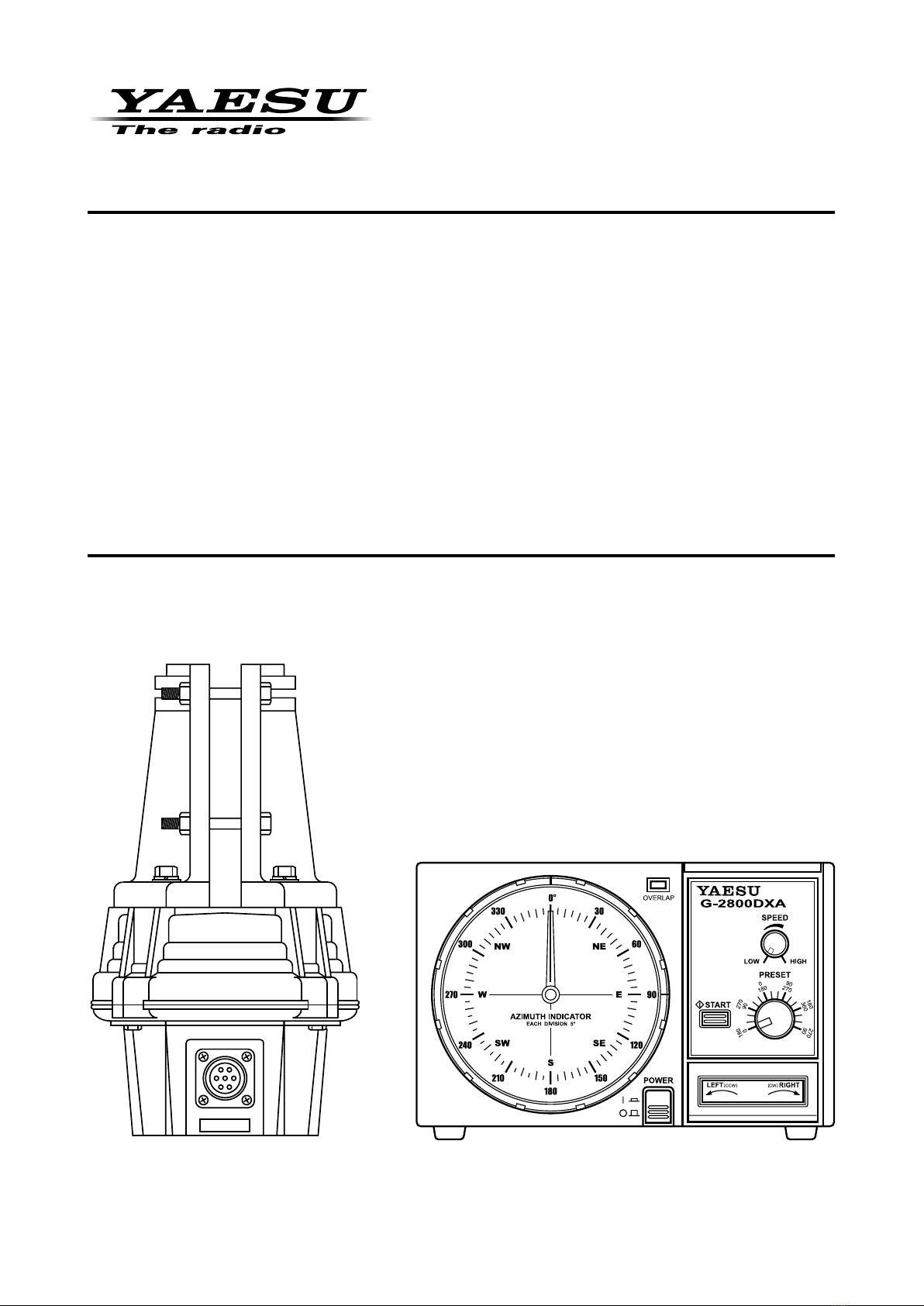
8G-800DXA / -1000DXA / -2800DXA User Manual
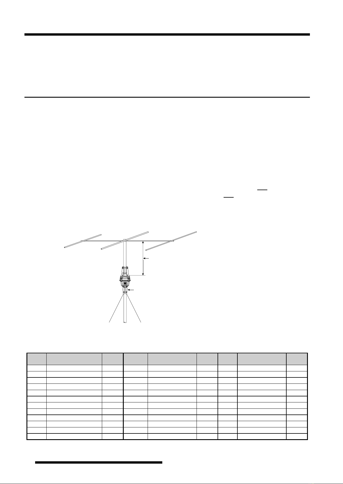
Mounting the Rotator and Antenna
INDOOR PERFORMANCE CHECK AND ALIGNMENT
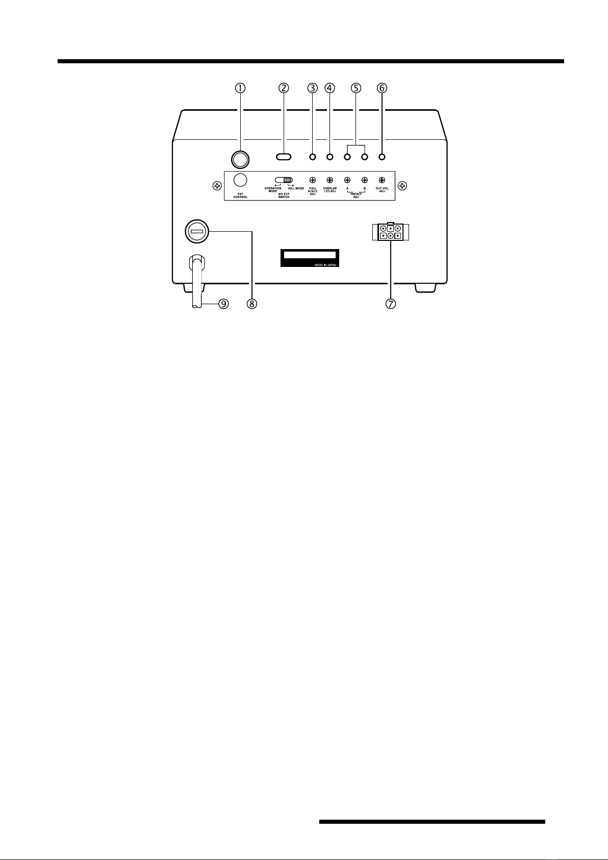
1. Temporarily connect the control cable between the
rotator unit and the controller.
2. Turn the SPEED control fully counter-clockwise,
and set the SELECT SWITCH on the rear panel to
the right (ADJ. MODE) position.
3. Check to be sure that the POWER switch on the con-
troller is set to “OFF”, then plug the controller’s AC
cable into your station’s AC outlet.
4. Set the controller’s POWER switch to “ON”. Verify
that the controller’s pilot lights have become illumi-
nated.
5. Press the LEFT (rotation) side of the seesaw switch,
and continue to hold it until the rotator reaches the
counter-clockwise position where it automatically
stops (“Left” represents counter-clockwise rotation
when the rotator is viewed from the top).
6. When the rotator has reached the left “stop” posi-
tion, release the LEFT switch, and check to see if the
controller’s indicator needle is pointing to 180° (S:
South).
If the indicator needle is out of alignment, grasp the
edge of the bezel around the bearing window, turn it
10° counter-clockwise, and pull it off. Then, grasp the
needle at its center and pull it straight off, replace the
needle to 180° (straight down), and replace the bezel.
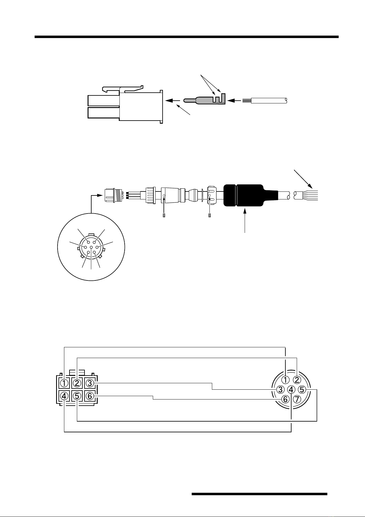
7. Just above the round connector jack on the rotator
unit, you will observe two raised calibration marks
(one each on the “rotating” bell and “fixed” base
of the rotator). These two marks should be directly
aligned with each other. If not, place a small piece of
masking tape on the rotating bell and the xed base of
the rotator unit, and make a calibration mark will be
used to verify the amount of rotation in the next step.
8. Press the RIGHT (rotation) side of the seesaw switch,
and continue rotating to the right until the calibration
marks (from step 7) are again precisely aligned. Now
check the indicator needle, which should also have
rotated fully 360° so as to be pointing exactly to 180°.
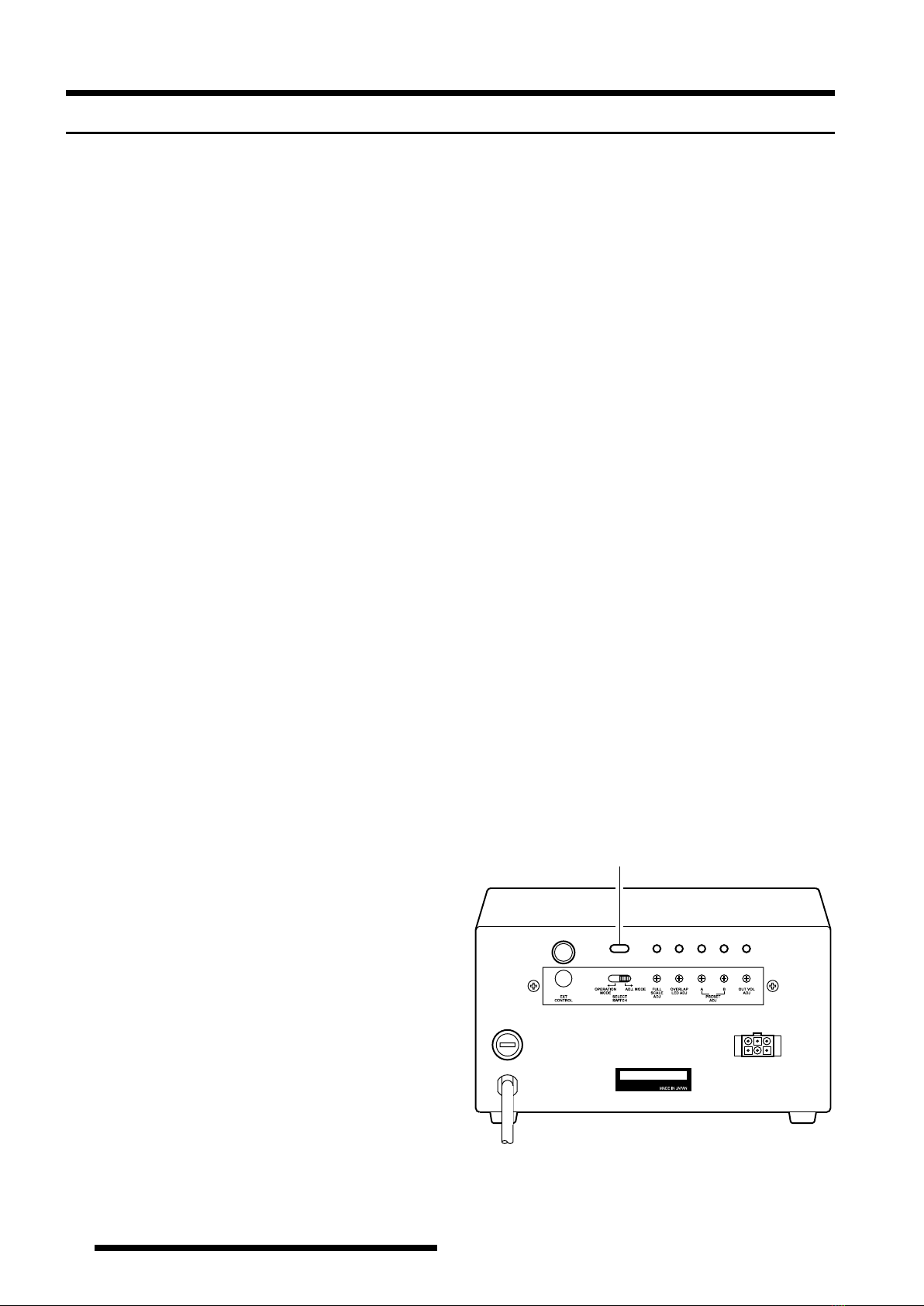
If the indicator needle is not pointing exactly to 180°,
go to the rear panel of the controller, and use a small
screwdriver to adjust the FULL SCALE ADJ po-
tentiometer (see the drawing to the right) so that the
indicator needle points exactly to 180°.
9. Press the RIGHT switch again, and continue rotation
to the right. You should observe the OVERLAP LED
becoming illuminated as rotation passes the 180°
point.
If the OVERLAP LED does not light up at the 180°
position, the OVERLAP LED ADJ potentiometer (on
the rear panel of the controller) may be used to align
the illumination threshold to the 180° point.
10. Check to verify that rotation automatically stops at
approximately 270° (West; representing a total rota-
tion range of 450° from the original starting point).
11. Press the LEFT and RIGHT (rotation) switches a
few more times, verifying that rotation appears to be
normal. If so, press the LEFT or RIGHT (rotation)
switch to set the rotator to 270° (West).
12. Set the PRESET control to 180° (fully counter-
clockwise), and press the START switch. The rotator
should rotate counter-clockwise, and stop exactly at
180°.
If not, go to the rear panel of the controller, and use
a small screwdriver to adjust the PRESET ADJ A
potentiometer so that the rotator stops at exactly 180°.
13. Set the PRESET control to 270° (fully clockwise),
and press the PRESET switch. The rotator should ro-
tate clockwise, and stop at exactly 450° (270°; West).
If not, go to the rear panel of the controller, use a
small screwdriver to adjust the PRESET ADJ B po-
tentiometer so that the rotator stops at exactly 450°.
14. Repeat steps 12 and 13 several times until the indica-
tor responds reliably to presetting small angles when
the rotator is near both ends of its range.
15. Set the SELECT SWITCH on the rear panel to the
left (OPERATION MODE) position, and turn the
POWER switch “OFF”.
16. This completes the ground-based testing of the rotator
and controller.
Controller Rear Panel
YAESU MUSEN CO., LTD.
SELECT SWITCH