Attonic ARFS-02 User manual
ARFS
Series
OPERATION MANUAL
ATTONIC CO., LTD
ATTONIC
Digital Force Gauge
ARFS-series

■Digital Force Gauge
It is the force-measuring instrument of the electronic
formula which can measure both tension and compression
power by single axis. Our design is for hand held use and
can be set with load testing stand. By using with a test
stand, it corresponds to a large area from the field of a
quality control to the research and development.
Digital Force Gauges are used well to check intensity or
movement of some parts in automobile industry, electric
industry and etc.
■Features
・Our Digital Force Gauge is down sized and has original
design for hand held use.
・The display value can be displayed reversely.
・Sampling Speed 1ms
・The digital range of display is max. 9999.
・Digimatic, Analog, RS-232C and Comparator out-put are
attached as standard accessory.
■Example Use
・Peak Holding Measurement and Tracking Measurement.
・Peak Holding Memory is 50 Measurements Value.
・The limit of HI(HIGH) and LO(LOW) can be made by
comparator out-put.
・Selectable 3 units (N、Kg f、lbf)
・Battery Volume can be checked on display.
・Power auto-off function
When there is no key 2-3minutes,a power supply is
turned off automatically.
-1- ATTONIC
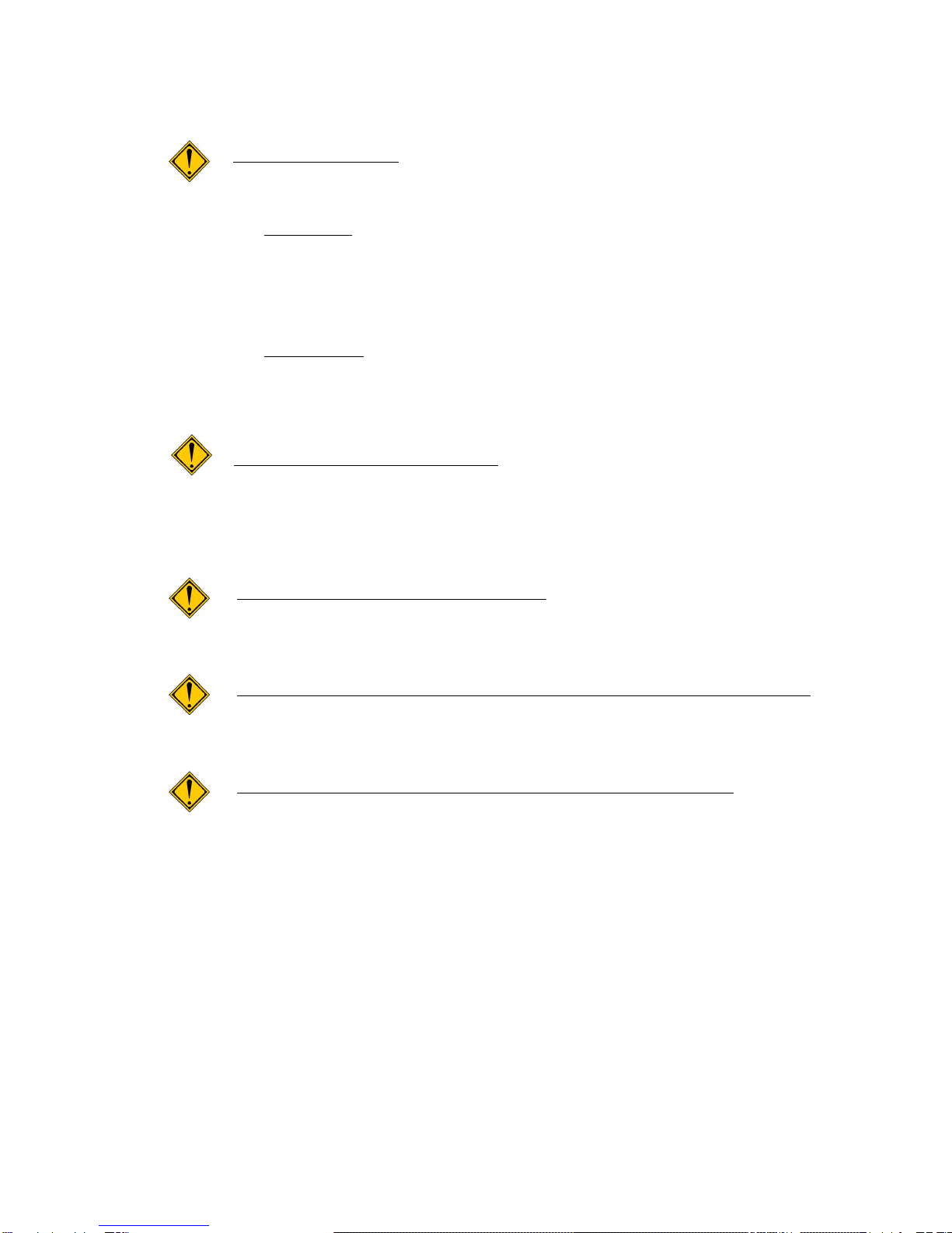
■Notes
Do not overload
The limit of overload capacity is 120% of full scale.
When the load is reached to 110% of Full Scale,
“ OVERLOAD “ is indicated on display. Keep it
within 100% of Full Scale. This is the cause for
the breakdown of load sensor.
※In case of over load setting 1 ~ 100 %,
“ OVER LOAD “ will be indicated on display when the
load is reached over your setting value.
(Regarding over load setting, please see page No.9.)
Do not use other adapter
Should other adapter be used, there are possibility
to breakdown or may lead to a fire. Also, do not
charge or operate unit in other voltage.
Do not impact or damage unit
This is the cause for the breakdown of load sensor or
other troubles.
Do not store and operate in the following conditions
※ Wet area ※ Where dew condensation
※ Dusty area ※ Where oil or chemicals
Do not disassemble, trouble-shoot and remodel
Should you perform any of these, that may cause
malfunction of the unit.
-2- ATTONIC

■Specifications
■Model & Indication Range
1When the max. display indication of 5000 and 9999 (10000), the
1
st
digits of display is changeable. The ability of sampling
speed and resolution become high in these max. display.
2In case of 100% to 110% of full scale of measuring range, the
display indicate the measuring value. However this measuring
value can not be used for your measurement. Incase of 110% over,
“ OVER LOAD “ is indicated on display. (This is in case of
over load setting ” 0 “)
※In case of over load setting 1 ~ 100 %, “ OVER LOAD “
will be indicated on display when the load is reached over
your setting value. (Regarding over load setting, please
see page No.9.)
-3- ATTONIC
Model Measuring Range Min. Indication
ARFS-02
0-2.000N/0-200.0gf/0-0.440lbf 0.001N/0.1gf/ 0.001lbf
ARFS-05
0-5.000N/0-500.0gf/0-1.100lbf 0.001N/0.1gf/ 0.001lbf
ARFS-1
0-9.999N/0-999.9gf/0-2.200lbf 0.001N/0.1gf/ 0.001lbf
ARFS-2
0-20.00N/0-2000gf/0-4.400lbf 0.01N/ 1gf/ 0.001lbf
ARFS-5
0-50.00N/0-5000gf/0-11.00lbf 0.01N/ 1gf/ 0.01lbf
ARFS-10
0-99.99N/0-9999gf/0-22.00lbf 0.01N/ 1gf/ 0.01lbf
ARFS-20
0-200.0N/0-20.00Kgf/0-44.00lbf 0.1N/ 0.01Kgf/ 0.01lbf
ARFS-50
0-500.0N/0-50.00Kgf/0-110.0lbf 0.1N/ 0.01Kgf/ 0.1lbf
■Standard Specifications
・Measuring Unit : Selectable 3 units N/Kgf(gf)/lb f
・Accuracy : ±0.2% of F/S
・Measurement : Peak Holding / Tracking
・Peak Holding : Digital Peak Holding
・Peak Holding Memory : 50 Measurement Values
・Sampling Speed : 1ms
・Display : 4 digits LCD
・Over Load Capacity : 120%
・Auto Power Off Term : 3 minutes
・Attachment : Included 7 Attachments S-1 to S-7
・Net Weight : About 1 kg
・Guarantee : 1 year
・Power Supply : Rechargeable Ni-MH Battery
(Charging Time : About 4 hours)
・AC Adapter :input:AC100-AC240V、output:DC9V、500mA
・Out-Put : ①Digimatic out-put ②RS-232C out-put
③ Reset signal in-put ④Comparator out-put
⑤ Over Load out-put ⑥Analogue out-put (±1V)
*Regarding the details for out-put, please refer page No.9.

■Standard Attachments
-4- ATTONIC
●ARFS-1~50
S-1 S-2 S-3 S-4 S-5
S-6
・Material:In case of 5N ~20N type=Aluminum
S-7
In case of 50N~500N type=Steel
●Model and Description
S-1・・・V-type(A)、S-2・・・V-type(B)、S-3・・・Cone-type、S-4・・・Flat-type
S-5・・・Hook-type、S-6・・・Extension Rod、S-7・・・Fork Hook-type
*Measuring Shaft・・・M6×1
●ARFS-02、05
SS-1 SS-2 SS-3 SS-4 SS-5
・Material: Aluminum
*Measuring Shaft・・・M3×0.5
●Model and Description
SS-1・・・V-type(A)、SS-2・・・V-type(B)、SS-3・・・Cone-type
SS-4・・・Flat-type、SS-5・・・Hook-type

■Description of Parts and Functions
-5- ATTONIC
AL-10N
Measuring Shaft
L
o
a
d
c
e
l
l
C
o
n
n
e
c
t
o
r
NO.01 234
A R F-20
MAX .Ca pac ity
2 0 0. 0 N
20.00 Kg 44.00 lb
CON.
DC
P D F
RE SET
MADE IN JAPAN
External Input/Output
LCD Disply
Reset Switch
Function Switch
Data Output Switch
Power Switch
Loadcell Connector
Serial Number Sticker
Power Connector
Protection Glass
Model and
Max.Capacity Sticker

■Explanation of each parts (1)
・ EXTERNAL INPUT / OUTPUT (CON.)
It is possible to do the various outside output and
display reset from outside. For details, see the
explanation of the output connector page No.9.
・ POWER CONNECTOR (DC)
Insertion connector of AC adapter for the charging.
The standard recharging time is about 4 hours after making
a power off. The charging condition can be confirmed by
display when making a power on. Also, it can be used
inserting AC adapter. However, it becomes the cause which
hastens the degradation of the charging battery. Recommend
to use without using AC adapter as much as possible.
・ GAIN ADJUST DIAL
ONLY MANUFACTURE SIDE (NEVER CHANGE THIS DIAL)
It is used when the calibration at the manufacture.
・ LCD DISPLAY
Using graphic LCD (liquid crystal), it is possible to
show a feature character, setting character, numbers and
charging scale in the display.
・ PROTECTION GLASS
Digital display is covered by protection glass.
・ MODEL AND MAX. CAPACITY STICKER
Model number and maximum display value of 3 units and
indicated.
・ POWER SWITCH (P)
On/Off button of the power. The buzzer sounds in case
of start the operation.
・ DATA OUTPUT SWITCH (D)
Output button for the digimatic signal and RS-232C signal
of the data. It outputs a digital signal firstly and it
outputs a RS-232C signal.
(Caution)
It outputs the digital signal when using a function
feature. Also, in case of function feature (FU), it can be
changed Peak Hold and Tracking, the reading of memory data
and various setting of value.
-6- ATTONIC

■Explanation of each part(2)
・FUNCTION SWITCH (F)
This button is for setting up each function. To change function
mode, keep to push about 6 seconds. (“FU” is indicated in
LCD Dispay), can be set up each function.
・RESET SWITCH
This button is for resetting data indication of peak-hold and
tracking.
Besides when the mode is function (FU), you can reset all of
the memory data (but cannot reset the data one-by-one), and can
alter the figure (then the figure is underlined) by this
button.
・SERIAL NUMBER STICKER
Serial number is mentioned on this sticker.
・MEASURING SHAFT
This shaft is for detecting the force.
The size of shaft screw is M6 X 1.
Attachment can be set on this top of shaft screw.
-7- ATTONIC

■Explanation of a button setting function (1)
Various functional set up in button operation.
●Set up the function
① Change Peak Hold (PEAK) and Tracking (TRUCK)
② Check Memory (MO) Data and Elimination of all memory data
③ Set up Comparator Function (HI)
④ Set up Comparator Function (LO)
⑤ Change Measuring Unit (UN)
⑥ Set up Over Load (OV)
⑦ Set up Power Auto Off(AP)
⑧ Set up Number of Digits on display / NP setting (NP)
⑨ Reverse Digital Display
Power switch is turned ON while pressed the P-button.
(Becomes MEASUREMENT MODE)
(When there is no key 2-3minutes,a power supply is turned
off automatically)
Keep to push F button about 6 seconds, indicate by FU
(function). (Becomes SETTING MODE)
Preparations the various setting were completed.
The programming procedure after FU display
① Change Peak Hold (PEAK) and Tracking (TRUCK)
Change the Peak hold (PEAK) and change the tracking (TRUCK)
when pressed the D button. (Initial setting : TRACK)
↓
Push F button
② Check Memory (MO) Data and Elimination of all memory data
”MO “ in the upper right side of the display.Can be
confirmed the memory date. The memory data is advanced
when press the D button. (from M01 up to M50)
Elimination of all memory data should press the RESET
button. (Each data is not eliminable)
The display indicate MO 0 when data is eliminated. (Initial
setting : 0)
↓
Push F button
③ Set up Comparator Function (HI)
Set up the upper limit of comparator function Figure rising
by D-button and Digit rising by RESET-button. When not
using this function, setting to the 0. (Initial setting : 0)
↓
-8- ATTONIC

■Explanation of a button setting function (2)
Push F button
④ Set up Comparator Function (LO)
Set up the low limit of comparator function. Figure rising
by D-button and Digit rising by RESET button. When not
using this function, setting to the 0.
(Initial setting : 0)
↓
Push F button
⑤ Change Measuring Unit (UN)
To push D button, display change from N→Kgf→lb f→
N・・・ (Initial setting : N)
↓
Push F button
⑥ Set up Overload (OV)
Count up by D button. Figure up by RESET button.
Setting value is %. It cannot set under 0.
When not using this function, setting to the 0.
(Initial setting : 0) In case of setting 0, “ OVER LOAD “
will be indicated on display when the load is reached from
100% to 110% of full scale.
↓
Push F button
⑦ Set up Power Auto Off(AP)
To push D button, Set up the Power auto off 1→release 0・・・
(Initial setting : 1)
↓
Push F button
⑧ Set up Number of Digits on display / NP setting (NP)
Push "D" button.
If you need 3 digits on display, please set"1".
If you need 4 digits, please set " 2 ".
It is possible to change number of digits by this function.
↓
Push F button
⑨ Reverse Digital Display
The Value becomes flashing & dark. To push D button, the
direction of display indication is reversed in upside down
position.
↓
Push F button
TO ① Change Peak Hold (PEAK) and Tracking (TRUCK)
Keep to push F button about 6 seconds, the gauge is now
ready to measure.
-9- ATTONIC

■Digital indication for function mode
■Digital indication for warning messages
-10- ATTONIC
OVER LOAD BATT
■Over Load Indication ■Low Battery Indication
PEAK
- 00 0 0
N
FU PEAK
-0 000
N
FU MO 0 PEAK
- 000 0
N
FU HI
PEAK
-0 000
N
FU LO PEAK
- 00 0 0
N
FU UN PEAK
- 000 0
N
FU OV
PEAK
- 000 0
N
FU
PEAK
- 0000
N
FU
PEAK
- 000 0
N
FU NP
PEAK
-0 000
N
FU AP
*Display reversed with D Switch
●It will become FU display if F Switch is pushed for about 6 seconds.
(Measurement functional stop state)
Next,if F Switch is pushed, a setup of each function can be performed.

■External Input / Output
*Connector of HIROSE brand HR25-9TR-16S is used.(16 pins)
Please prepare a plug HR25-9TP-16P.
Name of signal for each connector pin is as follows.
1.Analog output ・・・ ±1V
2.Analog GND
3.Signal input for External reset・・・ Indication reset
4.Input COM
5.Comparator HI ・・・ Open Collector Output (50V / 100mA)
6.Comparator GO ・・・ 〃
7.Comparator LO ・・・ 〃
8.Overload output ・・・ 〃
9.Output COM
10.RS-232C Rx ・・・
Please refer the following RS-232C Format
11.RS-232C Tx ・・・ 〃
12.Digimatic output (DATA)
13.Digimatic output (CK)
14.Digimatic output (RD)
15.Digimatic output (REQ)
16. GND
●RS-232C Format
1.Interfacing (Bit) Spec.
・Start Bit : 1 bit
・Date Length : 8 bit
・Stop Bit : 1 bit
・Parity : None
・Baud Rate : 9600 BPS
-11- ATTONIC
13
4 8
913
14 16
■Connector Form

ATTONIC CO., LTD.
6
00-5 HIGASHI TAKADACHO, TOYOHASHI
AICHI 441-8115 JAPAN.
TEL : (0532)-41-5357
FAX : (0532)-41-4826
URL:http://www.attonic.co.jp
E-mail:info@attonic.co.jp
This manual suits for next models
7
Table of contents


