AtVideo HDHS243 User manual
Please read this manual thoroughly before use, and keep it handy for future reference.
Design and specifications are subject to change without notice.
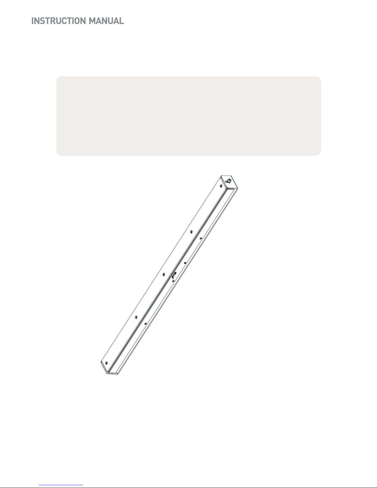
Height Strip Covert Camera

FCC COMPLIANCE STATEMENT
CE COMPLIANCE STATEMENT
CAUTION : Changes or modifications not expressly approved by the party responsible for
compliance could void the user’s authority to operate the equipment.
This device complies with Part 15 of the FCC Rules. Operation is subject to the following two
conditions: (1) this device may not cause harmful interference, and (2) this device must
accept any interference received, including interference that may cause undesired operation.
WARNING : This is a Class A poduct. In a domestic environment this product may cause
radio interference in which case the user may be required to take adequate measures.
FCC INFORMATION : This equipment has been tested and found to comply with the limits
for a Class A digital device, pursuant to Part 15 of the FCC Rules. These limits are designed
to provide reasonable protection against harmful interference when the equipment is
operated in a commercial environment. This equipment generates, uses, and can radiate
radio frequency energy and, if not installed and used in accordance with the instruction
manual, may cause harmful interference to radio communications. Operation of this
equipment in a residential area is likely to cause harmful interference in which case the user
will be required to correct the interference at his own expense.
2

1. Read these instructions.
2. Keep these instructions.
3. Heed all warnings.
4. Follow all instructions.
5.. Do not block any ventilat ion openings. Install in accord ance with the manufacturer`s
instructions.
6. Do not install near any heat sources such as radiators, heat registers, stoves, or other
apparatus (including amplifiers) that produce heat.
7. Only use attachments/accessories specified by the manufacturer.
8. Use only with the ca rt, stand, tripod, bracket, or table specified by
the manufacturer, or sold with the apparatus. When a cart is used,
use caution when moving the cart/apparatus combination to avoid
injury from tip-over.
9. CAUTION - THESE SERVICING IN STRUCTIONS ARE FOR USE BY
QUALIFIED SERVICE PERSONNEL ONLY. TO REDUCE THE RISK OF
ELECTRIC SHOCK DO NOT PERFORM ANY SERVICING OTHER THAN
THAT CONTAINED IN THE OPERATING INSTRUCTIONS UNLESS YOU
ARE QUALIFIED TO DO SO.
10. Use satisfy clause 2.5 of IEC60950-1/UL 60950-1 or Certified/Listed Class 2
power source only.
11. Indoor use only.
EXPLANATION OF GRAPHICAL SYMBOLS
IMPORTANT SAFETY INSTRUCTIONS
3
4

Step 1
Drill feed-thru hole for cable on mounting surface 63.27" above the finished floor.
63.27"
5

Step 2
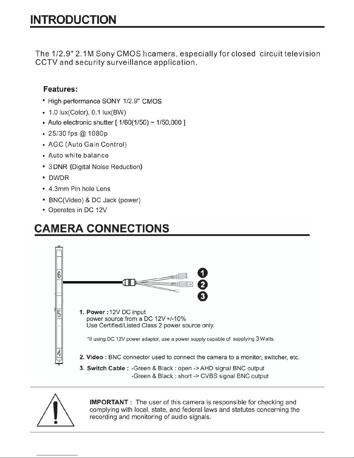
Feed wire through the 1.0 inch hole on the gimble mount.
6
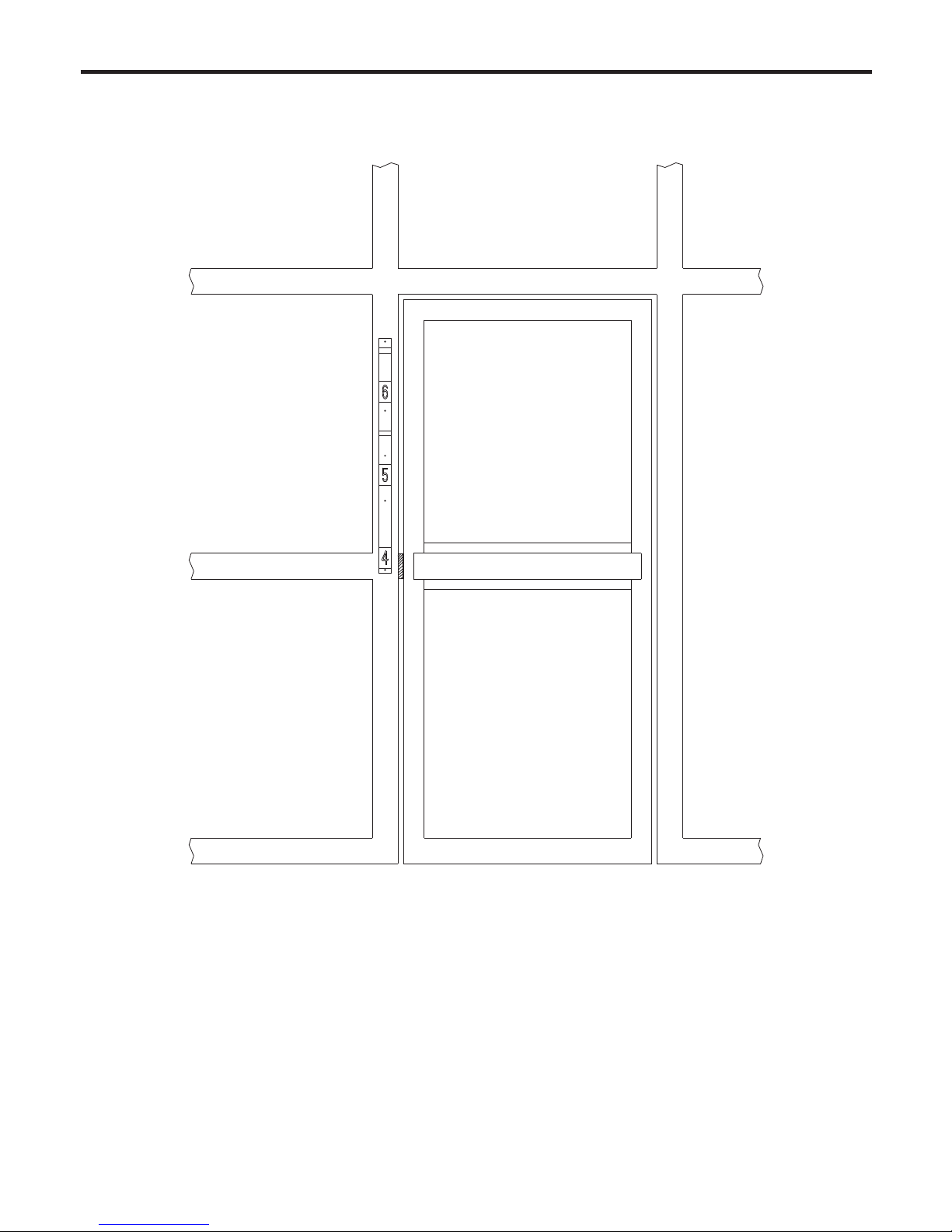
Step 3
Center the gimbal mount to mounting surface and mark the mounting holes for the gimbal mount on
the surface.
Secure the gimbal mount to the surface using installer supplied self tappers for aluminum frame
structure.
If mounting on soft surface such as drywall be sure to use to use anchors.
7
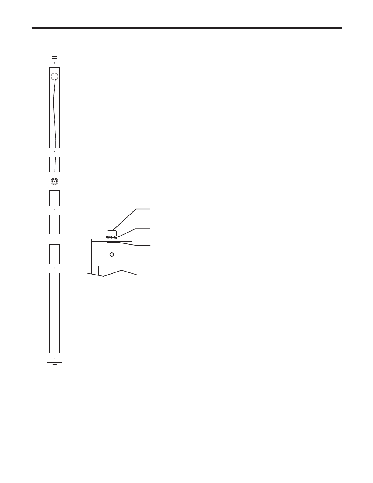
Step 4
Split lock washer between gimbal mount and housing
External tooth lock washer under head of bolt
Figure-1
M6 Allen head screw
Completing the housing installation
Remove the five white head M4 screws that hold the face plate to the housing
and set the face plate aside.
Feed the wire coming through the gimbal mount through the 3/4" hole in the
back of the camera housing.
Attach the camera housing to the gimbal mount using the M6 Allen head screws
and washer previously removed.
Place the external tooth washer between the housing and the gimbal mount then
the split lock washer on the M6 screw and insert the screw into the housing
through the gimbal mount and external tooth lock wasker.
Install the bolt and washers assembly at the bottom and top of the gimbal mount
finger tight. (See Figure-1)
After connecting the video and power to their proper connections replace the
face plate that was removed in an earlier step using the five screws.
Adjust the position of the housing in the gimbal mount for the proper view and
then tighten the top and bottom Allen head screws using an Allen head wrench.
Verify that the housing is in the proper position and is secure.
8

Optional Camera Height Setting
Figure-2
Figure-3
[ft] [cm]
1. The Height strip camera has the capability to be set in the housing at 5ft or
5.5ft above the floor.
The default setting of the camera is set to 5.5ft.
If the lower setting is desired the following housing change must be
completed.
* Remove housing from gimbal
* Note the position of the hole in the housing base for cable throughput
The cable hole is at the center of the mounting bracket
* Remove four Allen flat head screws along each side of the housing and
separate the front cover with the camera from the housing base.
Allen flat head screw
* From to to change the camera position. (See Figure-2)
* Replace the front cover with the camera to the housing base after
o
turning the cover 180 f
r
om original position.
Replace the three Allen head screws along each side of the housing
and continue the installation
2. Camera lens position can be adjusted up and down 5 degrees.
3. Two height marker strips are provided, one marked in feet
and one marked in centimeters. Use the appropriate one.
(See Figure-3)
o
5
o
5
1
2
12
9
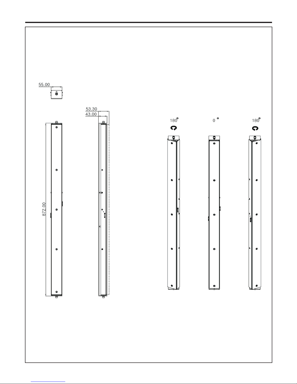
DIMENSIONS
HEIGHT STRIP CAMERA
55.0 x 43.0(53.3) x 872.0 mm
2.17 x 1.69(2.10) x 34.33 inch
10
Table of contents
Other AtVideo Security Camera manuals


