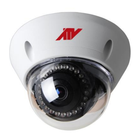
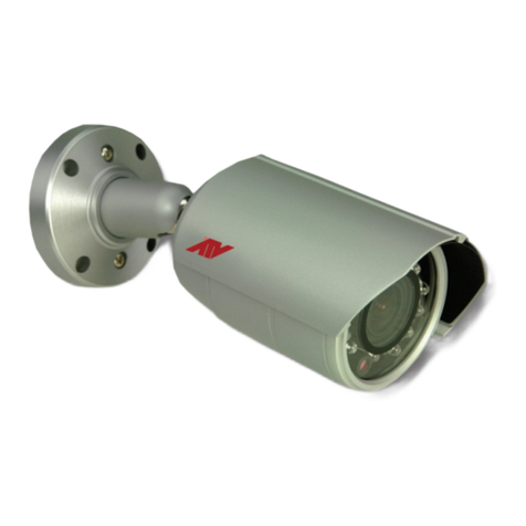
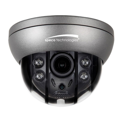
AtVideo CB236HD User manual

INSTRUCTION MANUAL
2MP
HD ANALOG CAMERA
CB236HD, CT236HD, CB2212HD
CT2212HD, CV2212HD
Please read this manual thoroughly before use and keep it handy for future reference.

2

3
CAUTION
RISK OF ELECTRIC SHOCK
DO NOT OPEN
CAUTION: TO REDUCE THE RISK OF ELECTRIC SHOCK,
DO NOT REMOVE COVER (OR BACK)
NO USER-SERVICEABLE PARTS INSIDE.
REFER SERVICING TO QUALIFIED SERVICE PERSONNEL.
WARNING
TO REDUCE THE RISK OF FIRE OR ELECTRIC SHOCK, DO
NOT EXPOSE THIS PRODUCT TO RAIN OR MOISTURE. DO
NOT INSERT ANY METALLIC OBJECTS THROUGH THE
VENTILATION GRILLS OR OTHER OPENINGS ON THE
EQUIPMENT.
CAUTION
EXPLANATION OF GRAPHICAL SYMBOLS
The lightning flash with arrowhead symbol, within an
equilateral triangle, is intended to alert the user to
the presence of uninsulated “dangerous voltage”
within the product’s enclosure that may be of
sufficient magnitude to constitute a risk of electric
shock to persons.
The exclamation point within an equilateral triangle
is intended to alert the user to the presence of
important operating and maintenance (servicing)
instructions in the literature accompanying the
appliance.

4
FCC COMPLIANCE STATEMENT
This device complies with Part 15 of the FCC Rules. Operation is subject
to the following two conditions: (1) this device may not cause harmful
interference, and (2) this device must accept any interference received,
including interference that may cause undesired operation.
FCC INFORMATION: This equipment has been tested and found to
comply with the limits for a Class A digital device, pursuant to Part 15 of
the FCC Rules. These limits are designed to provide reasonable
protection against harmful interference when the equipment is operated in
a commercial environment. This equipment generates, uses, and can
radiate radio frequency energy and, if not installed and used in
accordance with the instruction manual, may cause harmful interference
to radio communications. Operation of this equipment in a residential area
is likely to cause harmful interference in which case the user will be
required to correct the interference at his own expense.
CAUTION: Changes or modifications not expressly approved by the party
responsible for compliance could void the user’s authority to operate the
equipment.
This Class A digital apparatus complies with Canadian ICES-003.
Cet appareil numérique de la classe A est conforme à la norme NMB-003
du Canada.
CE COMPLIANCE STATEMENT
WARNING
This is a Class A product. In a domestic environment this product may
cause radio interference in which case the user may be required to take
adequate measures.

5
IMPORTANT SAFETY INSTRUCTIONS
1. Read these instructions.
2. Keep these instructions.
3. Heed all warnings.
4. Follow all instructions.
5. Do not use this apparatus near water.
6. Clean only with dry cloth.
7. Do not block any ventilation openings. Install in accordance with the
manufacturer’s instructions.
8. Do not install near any heat sources such as radiators, heat registers, stoves,
or other apparatus (including amplifiers) that produce heat.
9. Do not defeat the safety purpose of the polarized or grounding-type plug. A
polarized plug has two blades with one wider than the other. A grounding
type plug has two blades and a third grounding prong. The wide blade or the
third prong is provided for your safety. If the provided plug does not fit into
your outlet, consult an electrician for replacement of the obsolete outlet.
10. Protect the power cord from being walked on or pinched particularly at plugs,
convenience receptacles, and the point where they exit from the apparatus.
11. Only use attachments/accessories specified by the manufacturer.
12. Use only with the cart, stand, tripod, bracket, or table
specified by the manufacturer, or sold with the apparatus.
When a cart is used, use caution when moving the
cart/apparatus combination to avoid injury from tip-over.
13. Unplug this apparatus during lightning storms or when
unused for long periods of time.
14. Refer all servicing to qualified service personnel. Servicing is required when
the apparatus has been damaged in any way, such as power-supply cord or
plug is damaged, liquid has been spilled or objects have fallen into the
apparatus, the apparatus has been exposed to rain or moisture, does not
operate normally, or has been dropped.
15. CAUTION – THESE SERVICING INSTRUCTIONS ARE FOR USE BY
QUALIFIED SERVICE PERSONNEL ONLY. TO REDUCE THE RISK OF
ELECTRIC SHOCK DO NOT PERFORM ANY SERVICING OTHER THAN
THAT CONTAINED IN THE OPERATING INSTRUCTIONS UNLESS YOU
ARE QUALIFIED TO DO SO.
16. Use satisfy clause 2.5 of IEC60950-1/UL60950-1 or Certified/Listed
Class 2 power source only.

6
Table of Contents
1 Introduction.....................................................................................................................7
1.1 Features ............................................................................................................................. 7
2 Installation and Configuration.......................................................................................8
2.1 Package Contents.............................................................................................................. 8
2.2 Installing the Camera.........................................................................................................8
2.3 Connections.....................................................................................................................13
3 OSD Menu....................................................................................................................14
3.1 OSD Menu Structure........................................................................................................ 14
3.2 Lens.................................................................................................................................. 15
3.3 Exposure..........................................................................................................................15
3.4 Backlight ..........................................................................................................................16
3.5 White Balance..................................................................................................................16
3.6 Day & Night ...................................................................................................................... 17
3.7 NR.....................................................................................................................................17
3.8 Special.............................................................................................................................. 18
3.9 Adjust ...............................................................................................................................20
3.10 Exit.................................................................................................................................. 20
4 Appendix .....................................................................................................................21
4.1 Specification.................................................................................................................... 21

1 Introduction
1.1 Features
•1/2.9” SONY Exmor CMOS image sensor
•3.6mm fixed or 2.8-12mm varifocal lens
•True D/N (Auto, Day, Night)
•IR LEDs
•AHD, HD-TVI, HD-CVI, CVBS selectable
•Auto exposure control (1/50,000 ~ x30 second)
•White balance control (AWB, ATW, AWC, Indoor, Outdoor, Manual)
•BLC (Back Light Compensation)
•HSBLC (High Suppress Back Light Compensation)
•Digital WDR (Wide Dynamic Range)
•DNR (Digital Nosie Reduction)
•4 Motion detection areas
•4 Privacy areas
•Defect Detections (Live DPC, White DPC, Black DPC)
•Defog
•12VDC for Camera
•Use satisfy clause 2.5 of IEC60950-1/UL60950-1 or Certified/Listed Class 2 power source only.

8
2 Installation and Configuration
2.1 Package Contents
The package contains the following.
•Camera 1
•Instruction Manual (This Document) 1
•Template Sheet 1
•Accessory Kit 1
2.2 Installing the Camera
Carefully remove the contents from the box.
CB236HD - Fixed Bullet Camera
To mount the bullet camera, fix the base of the camera with the three screws provided in the
accessory kit.
Plastic Anchor
Mounting Screw

CB2212HD - VF Bullet Camera
1) To mounting the bullet camera, fix the base of the
camera with the three screws provided in the
accessory kit.
2) Adjust the camera angle and tighten the
mount using the L-wrench.
3) Open the lens cover and adjust zoom & focus.
4) Adjust sun-shield position.
Plastic Anchor
Mounting
Screw
L-wrench

10
CT236HD - Fixed Turret Camera
1) Paste the template sheet in place at the
proper position.
2) Remove the collar off the camera
by rotating it down.
3) Fix the base of the camera with the three
screws provided in the accessory kit.
4) Mount the collar back by rotating it
up.
Template
sheet
Plastic Anchor
Mounting
Screw
Collar
Collar

11
CT2212HD - VF Turret Camera
1) Paste the template sheet in place at the
proper position.
2) Remove the collar off the camera by
rotating it down.
3) Fix the base of the camera with the
three screws provided in the accessory
kit.
4) Mount the collar back by rotating it up.
Adjust zoom and focus using
screwdriver.
Mounting
Screw
Template
sheet
Collar

12
CV2212HD – VF Vandal Proof Dome Camera
1) Paste the template sheet in place at the
proper position.
2) Remove the front cover by loosening
the three locking screws with a
screwdriver.
3) Fix the pedestal by drilling locking holes
around the sticker and inserting four
expansion bolts into the holes and
fastening it with four locking screws. Adjust
it to an appropriate angle.
4) Fix the front component on the
pedestal by tightening the three
locking screws.
Template
sheet
Locking Screw
Expansion
Bolt
Locking
Screw
Locking
Screw

13
2.3 Connections
No.
Connector
Description
1
DC jack
Camera Power
2
BNC jack
Video Out
3
Dip switch
Select Video Type
The camera must be installed by qualified service personnel in accordance with all local and
federal electrical and building codes.
•Connecting Video Output connector
Connect the video output (BNC) connector to the video input.
•Connecting the Power
Connect power of 12VDC for the camera.
When using a 12VDC adapter, connect the positive (+) pole to the ‘+’ position and
the negative (-) pole to the ‘-’ position.
Use satisfy clause 2.5 of IEC60950-1/UL60950-1 or Certified/Listed Class 2 power source
only.
•Select Video type
Select Video type using dip switch-TVI, AHD, CVBS or CVI.
AC+
AC-
AC+
AC-
FGND
(Rx+)
(Rx-)
Tx+
Tx-
GND
RS-485 Controller
①
②
③

14
3 OSD Menu
3.1 OSD Menu Structure
MAIN MENU
LENS
EXPOSURE
BACKLIGHT
WHITE BAL
DAY&NIGHT
NR
SPECIAL
ADJUST
EXIT
LENS
MANUAL
EXPOSURE
SHUTTER
AGC
SENS-UP
BRIGHTNESS
D-WDR
DEFOG
RETURN
BACKLIGHT
OFF
BLC
HSBLC
WHITE BAL
AWB
ATW
AWCSET
INDOOR
OUTDOOR
MANAUL
DAY&NIGHT
EXT
AUTO
COLOR
B&W
NR
2DNR
3DNR
RETURN
SPECIAL
CAM TITLE
D-EFFECT
MOTION
PRIVACY
LANGUAGE
DEFECT
RS485
RETURN
ADJUST
SHARPNESS
MONITOR
LSC
VIDEO.OUT
RETURN
EXIT
SAVE&END
RESET
NOT SAVE
Note. OSD menu can be controlled by coaxial communication(UTC).
CVBS mode does not support OSD menu control.

15
3.2 Lens
MANUAL: Opens up Shutter in Exposure menu.
3.3 Exposure
SHUTTER:Select the Shutter speed level.
Auto, 1/25(30), 1/50(60), FLK, 1/200(240), 1/400(480), 1/1000, 1/2000, 1/5000, 1/10000,
1/50000, x2, x4, x6, x10, x15, x20, x25, x30
AGC: 1 to 15
SENS-UP: Select the Digital Slow Shutter level.
Off, Auto Sens-up: x2, x4, x6, x10, x15, x20, x25, x30
BRIGHTNESS: Adjust the Brightness. 1 to 100
D-WDR: Select the Digital WDR. Auto, Off, On Level: 0 to 8
DEFOG: Select the Defog mode. Off, Auto
Pos/Size: Use up, down, right, left buttons to adjust both position and size of area.
Gradation: 0 to 2
Default: Default Defog settings.
MAIN MENU
SENS-UP
EXPOSURE
LENS
MANUAL
SENS-UP
x4
EXPOSURE
SHUTTER
AUTO
RETURN
RET
BACKLIGHT
OFF
AGC
12
WHITE BAL
ATW
SENS-UP
OFF
D-WDR
DAY&NIGHT
EXT
BRIGHTNESS
35
NR
D-WDR
AUTO
LEVEL
5
SPECIAL
DEFOG
OFF
RETURN
RET
ADJUST
RETURN
RET
EXIT
SAVE&END
DEFOG
POS/SIZE
GRADATION
0
DEFAULT
RETURN
RET

16
3.4 Backlight
OFF, BLC, HSBLC
BLC: Prevents such a back light effect to secure a clear image under all illumination
environments.
Level: Low, Middle, High
Area: Use up, down, right, left buttons to adjust both position and size of area.
Default: Default BLC settings.
HSBLC: Mask the high light zone with specific color and level.
Select: Area1, Area2, Area3, Area4
Display: Off, OnUse up, down, right, left buttons to adjust both position and
size of area.
Black Mask: Off, On
Level: 0 to 100
Mode: All day, Night AGC Level: 0 to 255
Default: Default HSBLC settings.
3.5 White Balance
The screen color can be adjusted by using the White Balance function. It compensates for
deviations in the white color caused by changes in the color temperature of the light source so that
the colors are reproduced correctly.
AWB, ATW, AWCSET, INDOOR, OUTDOOR, MANUAL
AWCSET Push enter button to set the color balance.
MANUALBlue: 0 to 100
Red: 0 to 100
MAIN MENU
BLC
HLBLC
LENS
MANUAL
EXPOSURE
LEVEL
MIDDLE
SELECT
AREA1
BACKLIGHT
OFF
AREA
DISPLAY
ON
WHITE BAL
ATW
DEFAULT
BLACK MASK
ON
DAY&NIGHT
EXT
RETURN
RET
LEVEL
20
NR
MODE
NIGHT
SPECIAL
DEFAULT
ADJUST
RETURN
RET
EXIT
SAVE&END
NIGHT MODE
AGC LEVEL
150
RETURN
RET
MAIN MENU
MANUAL
LENS
MANUAL
EXPOSURE
BLUE
50
BACKLIGHT
OFF
RED
50
WHITE BAL
ATW
RETURN
RET
DAY&NIGHT
EXT
NR
SPECIAL
ADJUST
EXIT
SAVE&END

17
3.6 Day & Night
EXT, AUTO, COLOR, B/W
EXT: Day/ night mode is changed by external sensor on the IR board.
DN (Delay): 0 to 60
ND (Delay): 0 to 60
AUTO: Day/night mode is changed by AGC level of the video.
DN (AGC): 0 to 255
DN (Delay): 0 to 60
ND (AGC): 0 to 255
ND (Delay): 0 to 60
COLOR: Permanent color mode
B/WBurst: Off, On
IR Smart: Off, OnLevel: 0 to 15
Area: Use up, down, right, left buttons to adjust both position
and size of area.
3.7 NR
Select Digital Noise Reduction mode.
DNR: 2DNR: Off, Low, Middle, High
3DNR: Off, Low, Middle, High
MAIN MENU
D&N EXT
LENS
MANUAL
DN (DELAY)
3
EXPOSURE
ND (DELAY)
3
BACKLIGHT
OFF
RETURN
RET
WHITE BAL
ATW
DAY&NIGHT
EXT
D&N AUTO
NR
SPECIAL
DN (CDS)
205
ADJUST
DN (DELAY)
3
EXIT
SAVE&END
ND (CDS)
165
ND (DELAY)
3
RETURN
RET
B/W
IR SMART
BURST
OFF
LEVEL
8
IR SMART
ON
AREA
RETURN
RET
RETURN
RET
MAIN MENU
DNR
LENS
MANUAL
EXPOSURE
2DNR
MIDDLE
BACKLIGHT
OFF
3DNR
MIDDLE
WHITE BAL
ATW
RETURN
RET
DAY&NIGHT
EXT
NR
SPECIAL
ADJUST
EXIT
SAVE&END

18
3.8 Special
SPECIAL
CAM TITLE
OFF
CAMERA TITLE
D-EFFECT
0 1 2 3 4 5 6 7 8 9
MOTION
OFF
A B C D E F G H I J K
PRIVACY
OFF
L M N O P Q R S T U V
LANGUAGE
ENG
W X Y Z ( )
DEFECT
¯ ─ _ / = & : ~ , .
RS485
OFF
RETURN
RET
C L R P O S E N D
D-EFFECT
FREEZE
OFF
MIRROR
OFF
NEG.IMAGE
OFF
RETURN
RET
MOTION
SELECT
AREA1
DISPLAY
ON
SENSITIVITY
64
COLOR
GREEN
TRANS.
1.00
ALARM
ALARM
DEFAULT
RETURN
RET
VIEW TYPE
ALL
OSD VIEW
ON
PRIVACY
TIME
3
RETURN
RET
SELECT
AREA1
DISPLAY
COLOR
COLOR
WHITE
TRANS.
1.00
DEFAULT
LIVE DPC
RETURN
RET
AGC LEVEL
16
DEFECT
LEVEL
100
RETURN
RET
LIVE DPC
ON
WHITE DPC
ON
WHITE DPC
BLACK DPC
OFF
RETURN
RET
POS/SIZE
START
DPC VIEW
OFF
LEVEL
16
AGC
14
SENS-UP
x8
RETURN
RET
BLACK DPC
POS/SIZE
RS485
START
DPC VIEW
OFF
CAM ID
0
LEVEL
100
ID DISPLAY
OFF
RETURN
RET
BAUDRATE
9600
RETURN
RET
CAM TITLE: 15 alpha-numeric characters
D-EFFECT: Freeze: Off, On
Mirror: Off, Mirror, V-Flip, Rotate
Neg.Image: Off, On
MOTION: Off, OnSelect: Area1, Area2, Area3, Area4

19
Display: Off / OnUse up, down, right, left buttons to adjust both
position and size of area.
Sensitivity: 0 to 100
Color: Green, Blue, White, Red
Transparency: 0.00, 0.25, 0.75, 1.00
Alarm: View Type: Off, Block, Outline, All
OSD View: Off, On
Time: 0 to 15
Default: Default Motion settings.
PRIVACY: Off, OnSelect: Area1, Area2, Area3, Area4
Display: Off, Mosaic, Inversion, Color: Use up, down, right, left buttons
to adjust both position and size
of area.
Color: User, White, Black, Red, Blue, Yellow, Green, Cyan
Transparency: 0.25, 0.50, 0.75, 1.00
Default: Default privacy settings.
LANGUAGE: ENG (English), CHN1 (Chinese 1), CHN2 (Chinese 2), GER (German),
FRA (French), ITA (Italian), SPA (Spanish), POL (Polish), RUS (Russian),
POR (Portuguese), NED (Dutch), TUR (Turkish)
DEFECT: Live DPC: Off, OnAGC Level: 0 to 255
Level: 0 to 100
White DPC: Off, OnPos/Size: Use up, down, right, left buttons to adjust
both position and size of area.
Start: Close the iris then press enter button.
DPC View: Off, On
Level: 0 to 60
AGC: 0 to 14
Sens-up: x2, x4, x6, x8, x10, x15, 20, x25, x30
Black DPC: Off / OnPos/Size: Use up, down, right, left buttons to adjust
both position and size of area.
Start: Press enter button.
DPC View: Off / On
Level: 0 to 100
RS485: Set ID and baudrate to control OSD through RS485(RS485 port supported model only).

20
3.9 Adjust
SHARPNESS: Off, AutoLevel: 0 to 10
Start AGC: 0 to 255
End AGC: 0 to 255
MONITOR: LCDBlack Level: 0 to 60
Gamma: User, 0.45, 0.50, 0.55, 0.60, 0.65, 0.70, 0.75, 0.80, 0.85, 0.90,
0.95, 1.00
Blue Gain: 0 to 100
Red Gain: 0 to 100
CRTBlue Gain: 0 to 100
Red Gain: 0 to 100
LSC: Select the Lens Shading Compensation. Off, On
VIDEO OUT: PAL, NTSC
3.10 Exit
SAVE&END: Save and exit OSD menu.
RESET: Full factory reset
NOT SAVE: Exit the OSD without saving settings.
MAIN MENU
ADJUST
SHARPNESS
LENS
MANUAL
SHARPNESS
AUTO
EXPOSURE
MONITOR
LCD
LEVEL
6
BACKLIGHT
OFF
LSC
OFF
START AGC
120
WHITE BAL
ATW
VIDEO.OUT
NTSC
END AGC
255
DAY&NIGHT
EXT
RETURN
RET
RETURN
RET
NR
SPECIAL
LCD
ADJUST
EXIT
SAVE&END
GAMMA
USER
BLUE GAIN
50
RED GAIN
50
RETURN
RET
CRT
BLUE GAIN
50
RED GAIN
50
RETURN
RET
This manual suits for next models
4
Table of contents
Other AtVideo Security Camera manuals

