Q-Series® Power – BAQ-UP™ (QRED) Redundancy Switch with Backup Amplier – Installation & Operation Manual 2-1
CHAPTER 2: DESCRIPTION OF OPERATION
DESCRIPTION OF OPERATION
2. Description of Operation
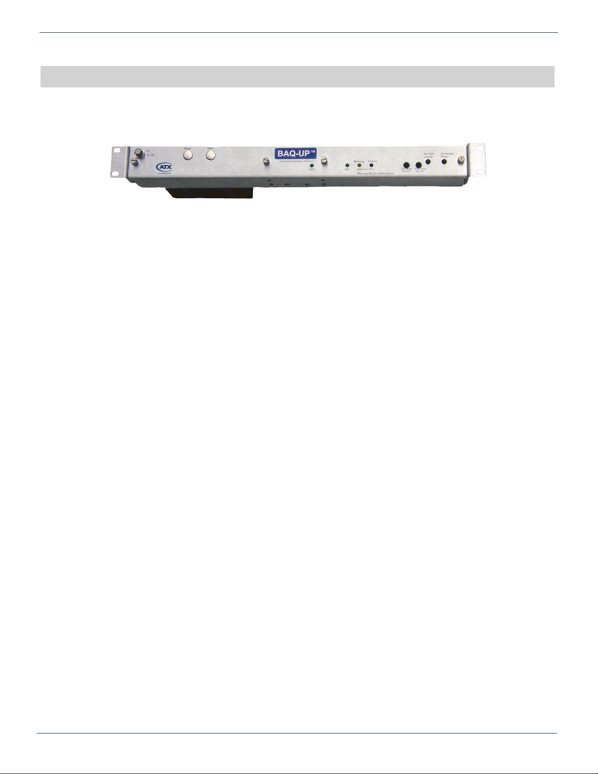
RF output levels of both the primary and the secondary ampliers are sampled and this sample is converted to a voltage
value. At initial power on, the system is switched to run on the primary amp. The yellow LED will ash slowly indicating the
reference levels need to be set. By pressing the “Set Reference Levels” switch, the microcontroller samples the output values
of both the primary amp and the secondary amp and stores the values as references. These values will be used to compare
with the sampled output values of both ampliers to conrm proper levels. At any time during the operation, one can always
press the “Controller Reset” switch to reset the microcontroller program and store the new sampled values.
The remote control switch is activated by closing the remote control contacts. Activation (closing the contacts) effects a switch
to the secondary amplier. Removing the contact closure will cause a switch back to the primary amplier. When the system
is switched to the secondary amp, the yellow LED will ash quickly to warn the user. The remote control switch can change
the system back and forth from the primary amp to the secondary amp by opening/closing the remote control contacts. The
system detects the remote control switch periodically to check its state. If a change in status is detected on the remote control
switch, the system will set to the primary or secondary amp according to the state of the contact closure.
During normal operation, if both outputs are within 3 dB (factory programmable) of the reference values, no action will be
taken. If the primary amp is down 3 dB or more and the secondary amp is not, the system considers the primary amp failed
and will switch to the secondary amp, set Alarm 1, and set the red LED on. The system needs to be reset (by the controller
reset push buttom on the front of the unit) at this point to get back to normal operation (after correcting the levels of the
primary amplier).
If both outputs are down 3 dB or more, the system considers the input is low and will set the red LED ashing quickly and set
the alarms. The system needs to be reset at this point to get back to normal operation (after correcting the input levels).
If the system is running on the primary amp and the secondary amp level is down 3 dB or more, the system considers the
secondary amp failed and will set Alarm 2 and set the red LED ashing slowly. The system should be reset at this point to get
back to normal operation (after making corrections to the secondary amp).
If the primary amp has failed and the microcontroller has switched to the secondary amp, the microcontroller can not perform
any additional switches because the detectors are unable to sample any signal when the secondary amplier is activated.
The system needs to be reset at this point to get back to normal operation (after correcting the primary amplier signal level).
The remote control switch is non-functional in this situation since a switch can not be forced to a failed primary amplier.
The total power within the bandwidth from the primary amplier coming into the RF switch compartment should not exceed 50
dBmV per channel. If only a portion of the TV channels is used, the maximum signal level per channel could be higher than
50 dBmV and the minimum signal level should be higher than 20 dBmV.
The recommended primary amplier output level is between 20 dBmV and 50 dBmV with all the TV channels loaded within
the passband. The secondary amplier operates 20 dB lower than the primary amplier during normal operation.
The system also stores the reference levels to the EEPROM on the microcontroller. When a power outage occurs, the system
can retrieve the reference levels from the EEPROM after the power comes back on. After power on, the system waits for
three minutes for the user to press the “Set Reference Levels” switch and will retrieve the levels from EEPROM if the switch is
not pressed. The system will also warn the user with a steady yellow LED light when it’s using the retrieved reference levels.
The user can press “Controller Reset” switch and then press the “Set Reference Levels” switch to overwrite the retrieved
levels. Please notice that when the user rst gets the system, there are reference levels stored into the EEPROM while the
system was tested in the factory.
During normal operation, Alarm 1 and Alarm 2 are energized (i.e. the Normally Open contact is connected to the Common
contact). This conguration ensures that the user be alerted when power goes down.