Au3Tech HW970 User manual


2
Catalog Index
I. Abstract.................................................................................................................. 3
II. Overview ................................................................................................................ 3
III. Product configuration ........................................................................................... 9
IV. Mechanical installation ........................................................................................ 11
V. Focus adjustment .................................................................................................14
VI. Maintenance .........................................................................................................15
VII. 1. Equipment installation and wiring.................................................................. 26
VIII. 2. The main interface description ........................................................................31
IX. 3. Equipment alarm and treatment......................................................................41
X. 4. Program update ............................................................................................... 43

3
Abstract
Key points
This manual covers the safe use, basic installation, factory settings, operating instructions,
and maintenance services of the HW970 (handheld welding) series products.
Audience
This manual is mainly applicable to the following staff:
⚫Installation Engineer
⚫Maintenance Engineer
⚫Operator
Please read this manual carefully and confirm to understand its contents before
using this product.
Modify record
The record modification accumulates the description of each document update. The
latest version of the document contains updates from all previous document versions.
The company reserves the right to modify the products and product specifications in
this manual without prior notice.
Overview
This manual describes the safe use, basic installation, factory settings, operation
instructions, and maintenance services of the HW9XX (handheld welding) series

4
products. There are many specific optical and mechanical custom configurations, and
this manual only introduces its main unit components.
Laser welding is a new welding method and handheld laser welding is more widely in
used. The handheld laser welding head has the advantages of beautiful appearance,
small and light weight, wide use range, simple operation, and fine weld seam, which
greatly improves the welding efficiency and quality. Hand-held laser welding solves the
existing welding problems such as poor welding of corners, insufficient welding, post-
processing of welds, unsightly welds and so on, which makes it the first choice for most
metal welding.
Safety Instructions
Please read the following safety precautions and suggestions carefully before operating
the laser and handheld laser welding head.
1. Please observe all safety instructions for laser (including but not limited to
descriptions of laser and the related chapters in this document)
2. Please ensure that do not look directly at the laser beam at any time or under any
circumstances. Do not look at the laser emitter port directly even if wearing laser
protective goggles.
3. It is forbidden to aim the laser at any human body, animal, vehicle, sky, etc. The
operator shall be legally liable for the (direct, indirect and incidental) injury to the
object, and the company shall not bear any liability and loss.
4. When using laser, wear laser protective goggles of the corresponding wavelength
to protect your eyes from the threat of laser.
5. At any time, please turn on the power of the controller and other control parts
before turning on the power of the laser. Otherwise, it may cause injury by
uncontrollable laser beam.

5
6. Any repair or maintenance must be done by professionally trained personnel!
Professionals must have received safety training, understand possible hazards
and be familiar with safety measures to deal with hazards.
Product appearance

6
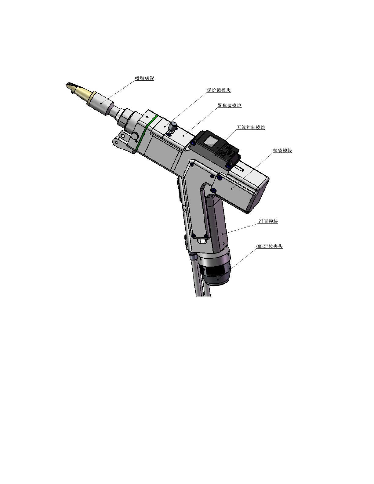
Figure 1 - Appearance of HW970
Structure composition
7
As shown in Figure 2, the welding head consists of seven basic units: QBH
connector, collimator lens unit, galvo-lens unit, wireless control unit, focus lens unit,
protection glass unit and nozzle unit.
Figure 2 - Structure of HW970
⚫QBH connector: complete the access and lock of the optical fiber connector.
⚫Collimator unit: complete the fiber collimation function and collimate the
incident laser into a parallel beam.
⚫Galvo-lens unit: Vibrate and reflect the collimated parallel laser at a certain
angle to change the direction of the original beam and the shape of the spot.
Nozzle unit
Protection glass unit
Focus lens unit
Wireless control unit
Collimator lens unit
QBH connector
Galvo-lens unit

8
⚫Wireless control unit: quickly adjust some high-frequency parameters.
⚫Focus lens unit: Focus the reflected beam into a convergent beam with high
power density.
⚫Protection glass unit: The protective glass can protect the focusing lens from
the damage of returning slag and prolong the service life of the focus lens.
⚫Nozzle unit: guide the focused beam to the workpiece, and generate high-
speed airflow to protect the molten pool from oxidation to achieve high-quality
welding results. You can also adjust the focus distance by adjusting the nozzle
length.
Product Highlights
⚫Cool appearance, ergonomic design, comfortable to grip
⚫Adjustable spot size, high welding firmness, beautiful lines
⚫Wireless control module, quick adjustment of parameters, one button to
complete wire feeding or rewinding
⚫The light spot can be adjusted to the center position
⚫Selection of high-quality precision optical components, excellent and stable
beam quality
⚫Compact structure design, high dustproof level

9
Product configuration
HW970 handheld laser welding head is mainly used for plane processing applications
within 2000W, and has very high versatile. Standard configuration model: HW970-Z50-
F150.
Configuration parameter
Parameter name
Technical indicators
Maximum applicable laser power
2000W
Optical fiber interface type
QBH
Focus lens specifications
Dia.=20mm,F=150mm
Collimating lens specifications
Dia.=20mm,F=50mm
Maximum clear aperture diameter
16mm
Laser wavelength
1064nm
Welding head weight
≤1000g
Maximum external size of welding head (width)
47mm
Nozzle size
Outer diameter 10mm, tolerance -
0.02mm to -0.04mm, length 72.5mm
Configuration list
Product name
Quantity
Handheld laser welding head
1set
Spare copper nozzle
6pcs
Spare protection glass
5pcs
Note: The above table is only for the standard factory configuration
Operation steps

10
1.Connect the circuit between the laser, the controller and the galvanometer driver.
Connect the power cord. For the wiring method, refer to the electrical control section of
the user manual.
2. After getting the laser welding head, connect the optical fiber connector firstly, and
then connect the air pipe, water pipe and switch circuit. (Thedetailed installation
method of each connector is described later)
3. Turn on the power of the controller and wait for the screen of the laser controller to
start up, then turn on the laser switch and the water cooler switch.
4. Set the relevant values on the controller screen (refer to the <User Manual Electric
Control Part> to set various parameters)
5. Put on goggles, hold the welding head with the welding head facing the metal welding
piece, and observe whether there is red light at the copper nozzle of the welding head.
If there is no red light, check whether the laser emits light normally.
* Note: Observe the red light from the side of the welding head, and it is strictly
forbidden to look directly at the laser beam with your eyes.
6. Position the welding parts, adjust the angle of the welding head to make the red light
shine on the seam to be welded, and the copper nozzle touches the welding parts, and
then manually turn the switch on the welding head to start light welding.
*Note: if only part of the red light comes out of the nozzle or the red light cannot be seen
at all, do not emit the laser.

11
Mechanical installation
Cooling water loop installation
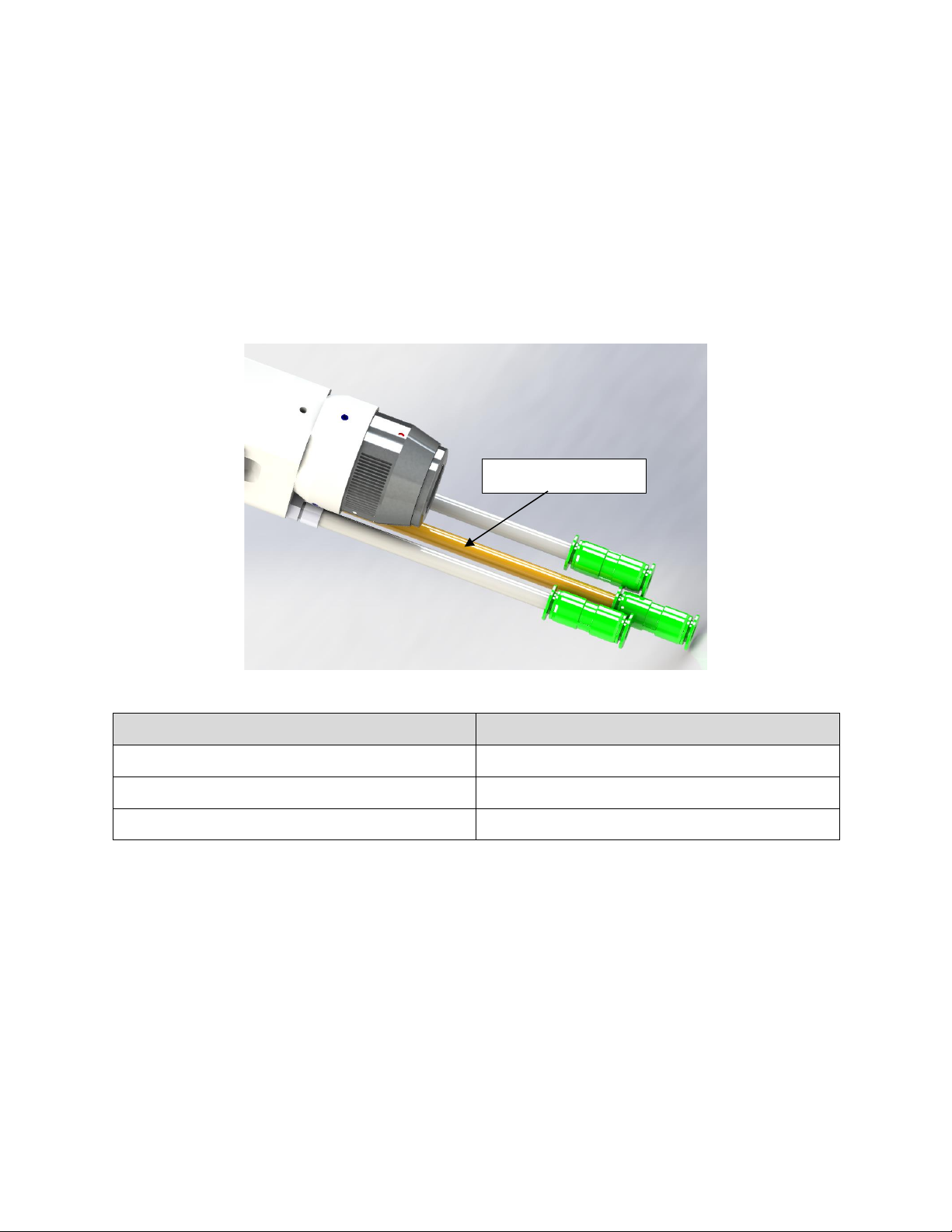
The HW970 handheld welding head is equipped with a set of cooling water channels. It
should be noted that when the laser power is greater than 500 watts, it is recommended
to use water cooling. From Figure 3, you can see the position and number of the water
cooling ports, and the table below lists the recommended water flow speeds in detail.
The design of the water-cooling interface is a closed loop system. External water supply
can be used freely, but the requirements in the list must be met.
Figure 3 HW970 water cooling interface
Parameter name
Parameter value
Cooling water pipe diameter (outer diameter)
6mm
Minimum flow rate
1.8liters/minute(0.48gpm)
Inlet pressure
170-520kPa (30-60 psi)
Inlet temperature
≥room temperature/>dew point
Hardness (relative to CaCO3)
<250mg/liter
pH range
6 to 8
Acceptable impurity particle
Diameter < 200 microns
Pneumatic installation
Impurities in the welding gas such as hydrocarbons and water vapor can damage
Cooling water inlet
Cooling water outlet
12
the lens. The following table shows the recommended welding gas specifications. The
higher the gas purity is, the better the quality of the welding gap is.
Impurities can be filtered out in the gas supply pipeline, but oxygen and water vapor
can penetrate into the optical path system through non-metallic materials, which is the
source of dust and hydrocarbons. It is recommended to use stainless steel accessories,
and a filter that can remove particles as small as 0.01 microns must be used for
purification.
It is recommended to use a pressure gauge with a stainless-steel diaphragm.
Industrial pressure gauges will inhale air. If a rubber diaphragm is used, hydrocarbons
will be generated due to aging and other reasons.
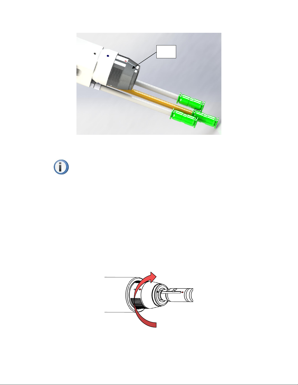
HW970 provides 1 way welding gas connection. The outer diameter of the gas pipe
is 6mm. As shown in Figure 4 below.
Figure 4 HW970 pneumatic interface
Welding gas
Purity
Nitrogen
99.99%
Argon
99.998%
Helium
99.998%
Optical fiber interface
The HW970 is suitable for most industrial laser generators. It is equipped with a
collimator lens assembly.
The connection between the end of the optical fiber and the welding head is called
the optical fiber connector. HW970 comes standard with QBH optical fiber connector, as
Pneumatic interface
13
shown in Figure 5 below.
Figure 5 HW970 optical fiber input interface-QBH
Note: The optics must be kept clean, and all dust must be removed before use. If
the welding head is to insert the optical fiber vertically, the welding head must be
rotated 90 degrees to a horizontal position, and then insert the optical fiber to
prevent dust from entering the interface and falling on the surface of the lens. Fix
the laser head after inserting the optical fiber.
Fiber rod insertion and locking
First, align the red dots on the end face of the QBH interface with the red dots of
the rotating handwheel; then, remove the QBH dust cap, align the red mark of the fiber
output end with the QBH red mark, and insert it straight to the bottom; next, rotate the
QBH hand wheel clockwise to reach the right position when hearing the sound of "Da",
then pull the handwheel upwards and turn it clockwise to the end again. As shown in
Figure 6 below.
Figure 6 HW970 QBH fiber rod insertion and locking diagram
QBH

14
Focus adjustment
Adjust focus position
The welding head can adjust the focus position. The adjustment method is to rotate
the locking ring counterclockwise. After loosening, adjust the copper nozzle extend the
length to obtain the required spot energy. After adjusting the position, tighten the locking
ring to lock the copper nozzle in the position just adjusted. There is a scale on the
copper nozzle, which is convenient and quick to adjust, as shown in Figure 7:
Figure 7 HW970 Focus position adjustment knob
Spot centering adjustment
Adjust the light spot to the horizontal center position of the nozzle.
Adjustment method: power on the HWS5000 welding system controller and then set the
"Width" to 0mm on touch screen → click "advanced parameters" → enter the password
"2000" → click "ENTER" → set the "optical core offset" parameter. When the "optical
core offset" parameter is set to be small, the optical core is shifted to the right; when the
"optical core offset" parameter is set to be large, the optical core is shifted to the left; set
appropriate parameters so that the optical core is in the center.
Locking ring

15
Figure 8 Adjusting the optical core offset parameters
Maintenance
Welding head cleaning and maintenance
When the welding head is used, a layer of black ash is attached to the copper
nozzle. This is the spark sputtering after the metal is heated, and then attaches to the
nozzle. There is also some dust in the air. After use, wipe the nozzle gently with a clean
cloth. Then, clean the dust on the welding head; in a relatively clean environment, pull
out the drawer and check whether the protective lens is clean. When the welding head
is not in use, plug the copper nozzle with tape or a rubber cap to prevent dust from
entering the lens. If you unplug the fiber connector, immediately block the hole of the
fiber input connector (QBH) with a dust cap to prevent dust from entering the fiber
connector.
Clean the lens
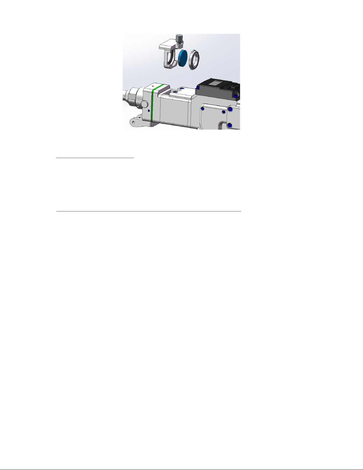
There is a lower protection glass at the front of the welding head to protect the focusing
lens. When impurities or foreign matters are attached to the protection glass, the lens
will be damaged. Therefore, the lens needs to be maintained regularly. It is
recommended to check it before start. Please refer to Figure 9 for lens structure.
16
Figure 9 HW970 protection glass module split diagram
■Lens cleaning tools:
PE gloves or finger cots, polyester cotton swabs, absolute ethanol, rubber air
blower (clean compressed air), etc.
■Lens cleaning method and matters needing attention:
(1)Wear finger cots on the thumb and index finger of the left hand;
(2)Spray ethanol on the polyester cotton swab;
(3)Gently pinch the side edge of the lens with the thumb and index finger of the left
hand. (Note that the finger cot cannot touch the surface of the lens to avoid leaving
traces);
(4)With the lens facing both eyes, hold the polyester cotton swab in your right
hand, gently wipe the lens from bottom to top or from left to right in a single direction (do
not wipe back and forth to avoid secondary pollution of the lens), and use rubber air
blower (clean compressed air) blows the surface of the lens. Both sides should be
cleaned. After cleaning, reconfirm that there are no residues of the following: detergent,
floating dust, foreign matter, and impurities.
17
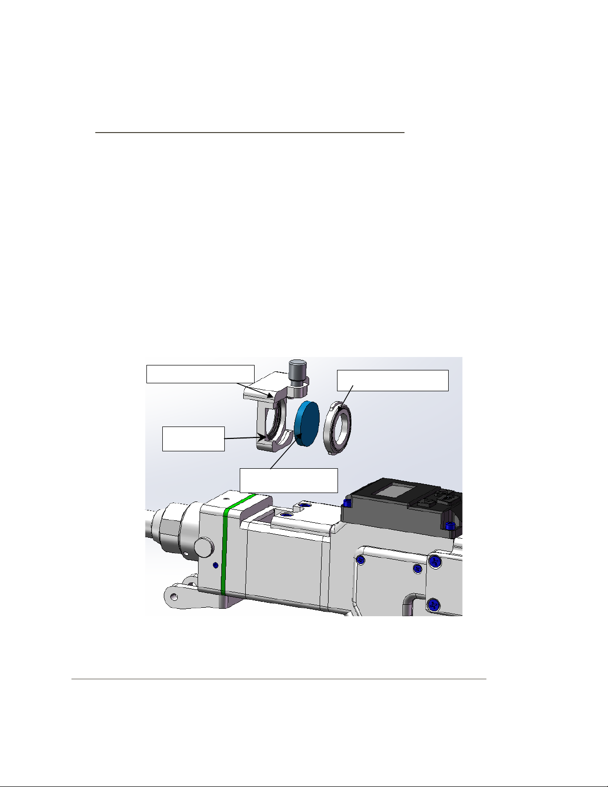
Removal and installation of lens
The entire process must be completed in a clean place, and PE gloves or finger
cots must be worn when removing and installing the lenses.
■ Disassembly and assembly of the lower protective lens:
Protective lens is a vulnerable part and needs to be replaced after damaged.
(1)As shown in Figure 10, loosen the locking screws, pinch both sides of the
drawer-type lens holder and slowly pull out the protective lens drawer;
(2)Rotate the protective lens cover 90° to remove the protective lens cover; take
it out from above Lens;
(3)Clean the lens, protective lens drawer and sealing ring. If the sealing ring is
damaged, replace it with a new one;
(4) Install the cleaned (or replaced) lens (regardless of the front and back) to the
protective lens in the drawer;
(5) Reinstall the protective lens cover;
(6) Reinsert the protective glass holder back into the welding head, and tighten the
locking screw.
Picture 10 HW970 protection glass split diagram
■Disassembly and assembly of the upper protective glass and focusing lens:
Protection glass drawer
Protection glass
Protection glass cover
Sealing ring
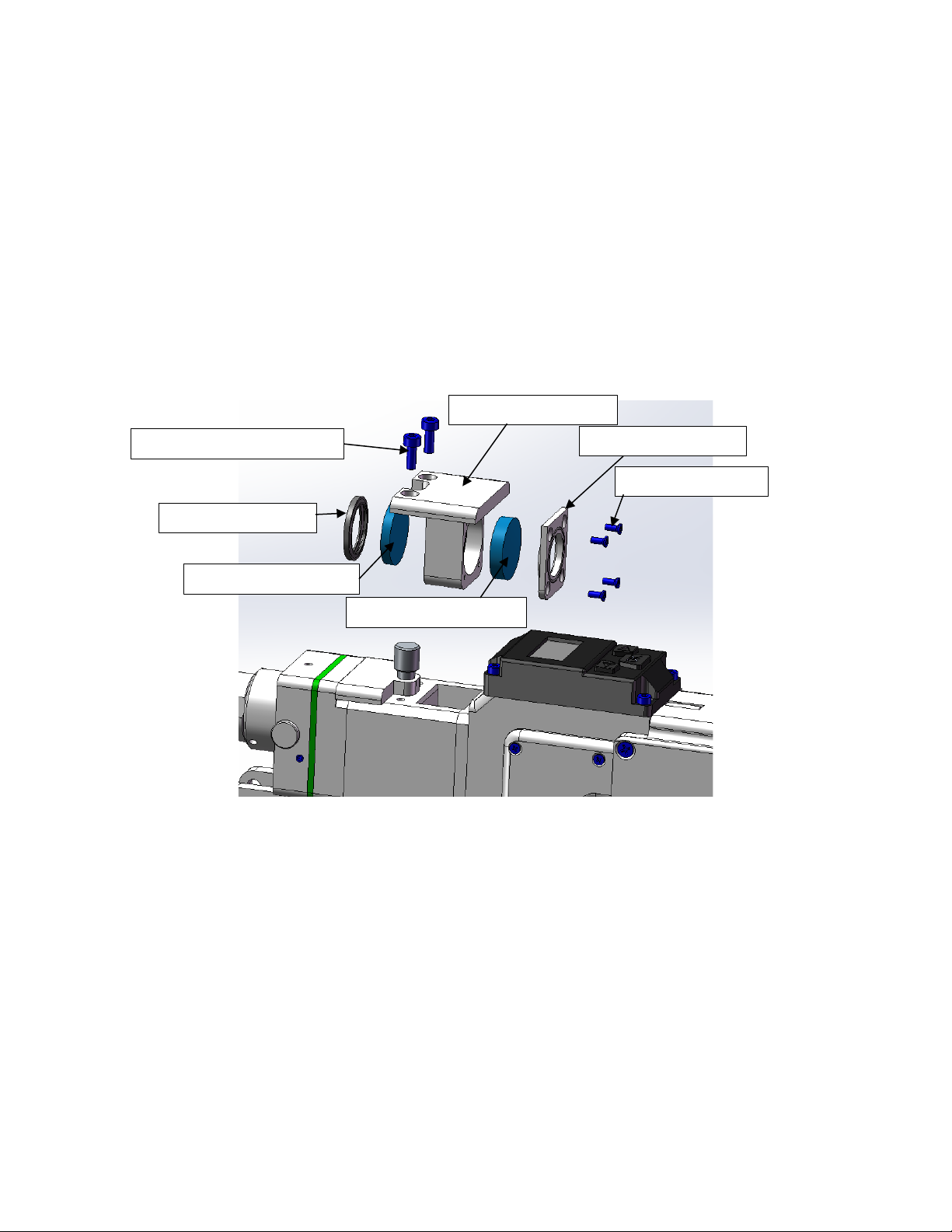
18
(1)As shown in Figure 11, loosen two M3X8 Hexagon socket screws, pinch both
sides of the drawer-type lens holder and slowly pull out the focusing lens drawer;
(2)Remove focusing lens: use a small cross screw to loosen four M2X5 Phillips
screws, remove the focusing lens cover; take out the focusing lens D20-F150
(3)Remove the protective glass: carefully remove the D20.55 sealing ring, and take
out the protective glass D20X3.
(4)Install the cleaned (or replaced) lens into the focus lens drawer
(5)Reinstall the focusing lens cover and D20.55 sealing ring.
(6)Reinsert the focusing lens drawer back into the welding head, and tighten the
locking screw.
Figure 11 Split diagram of upper protective glass and focusing lens on HW970
Replace the copper nozzle:
In the process of laser welding, the nozzle will touch the welding pieces and rub against
the metal parts. Nozzle is consumable accessory and needs to be replaced after a
period of use. The nozzle equipped is a combination nozzle, which is composed of a
M3X8 Hexagon socket screws
D20.55 sealing ring
圈
Protective lens D20X3
Focusing lens drawer
M2X5 Philips screw
Focusing lens cover
Focusing lens D20-F150

19
stainless steel bottom tube and a copper nozzle. The copper nozzle has different styles
and can be used in different scenarios. The corresponding copper nozzle is required to
use different thickness of welding wire. Refer to Figure 12.
■Replace nozzle:
(1)Before replacement, the laser enable should be turned off, and the welding
head should be facing in front with no one ahead;
(2)Unscrew the copper nozzle counterclockwise;
(3)Replace with a new nozzle.
Fig. 12 diagram of nozzle replacement
Direction of unscrewing
20
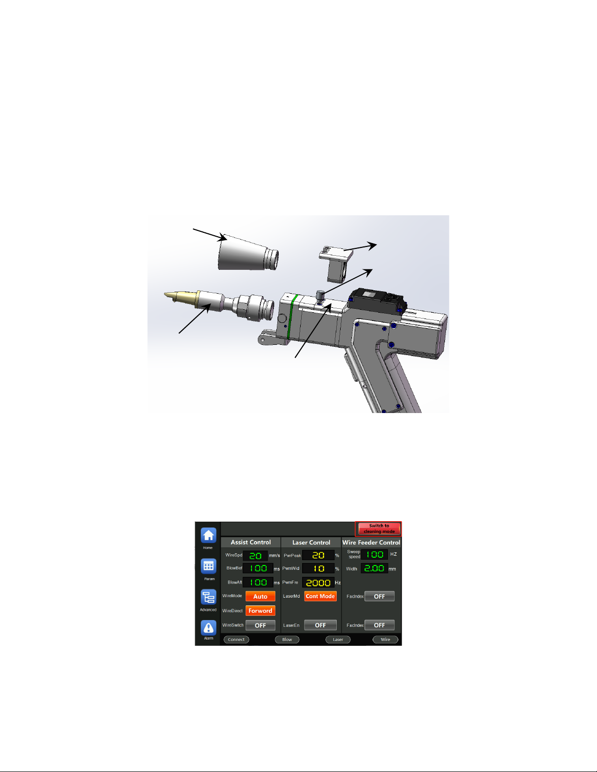
Switching to cleaning mode
Replace with cleaning parts
Loosen the screw, then replace the nozzle module with a dustproof light transmission
frustum.
Replace the focus lens module (D20-F150) with the focus lens module (D20-F600)
Enable the cleaning mode on the touch screen
Click the red button "Switch to cleaning mode" on the upper right of the welding
interface.
focus lens module - F600
focus lens module - F150
Dustproof frustum
copper nozzle module
screw
Table of contents
Other Au3Tech Industrial Equipment manuals

Popular Industrial Equipment manuals by other brands


PCB Piezotronics
PCB Piezotronics M261B03 Installation and operating manual

Amber
Amber api SmartScan V5.0 quick start guide

Vaillant
Vaillant 010038384 Installation and maintenance instructions

Eaton
Eaton PKE65/AK/XTU-65-SP Instruction leaflet

DriSteem
DriSteem Rapid-sorb quick start guide

MUSASHI ENGINEERING
MUSASHI ENGINEERING ShotMaster 300SX instruction manual


