Au3Tech C4 User manual

C4 Cutting head Users Manual
By Au3tech Research Pty Ltd

Copyright © AU3TECH RESEARCH PTY LTD
C4 Cutting head Users Manual By Au3tech Research Pty Ltd
2
Introduction
Overview
This document mainly describes the appearance, application scenarios,
installation, debugging, operation, maintenance, etc of C4 fiber laser
process head.
Reader Objects
This document mainly is applicable to the following personnel:
•Installation engineers
•Maintenance engineers
•Operators

Copyright © AU3TECH RESEARCH PTY LTD
C4 Cutting head Users Manual By Au3tech Research Pty Ltd
3
Table of Content
Introduction....................................................................................................................................2
Table of content .............................................................................................................................2
1 Overview ......................................................................................................................................4
1.1 Product Overview.......................................................................................................................4
1.2 Products feature.........................................................................................................................5
1.3 Cutting head parameters...........................................................................................................5
2 Structure Specifications.............................................................................................................6
2.1 C4 Fiber laser cutting head brief................................................................................................6
2.1.1 C4 flatbed cutting head...........................................................................................................6
2.1.2 C4 3D cutting head.................................................................................................................7
2.1.3 C4 fine cutting head................................................................................................................8
3 Installations.................................................................................................................................9
3.1 Pre-installation preparation........................................................................................................9
3.2.1 C4-QBH100-F125 and C4-QBH100-F150........................................................................10
3.2.2 C4-3D-QBH100-F125 .......................................................................................................11
3.2.3 C4-FC-QBH100-F50.........................................................................................................12
3.4 QBH Connection......................................................................................................................14
4 Focus Adjustments...................................................................................................................15
4.1 Focus centering .......................................................................................................................15
4.2 Z position adjustments.............................................................................................................16
5 Operation &Maintenance..........................................................................................................17
5.2 Collimator and focus lens maintain..........................................................................................19
5.2.1 Take out of lens holder.........................................................................................................19
5.2.2 Assemble the lens holder .....................................................................................................19
6 Technical Indexes.....................................................................................................................21
Copyright © AU3TECH RESEARCH PTY LTD
C4 Cutting head Users Manual By Au3tech Research Pty Ltd
4
1Overview
1.1 Product Overview
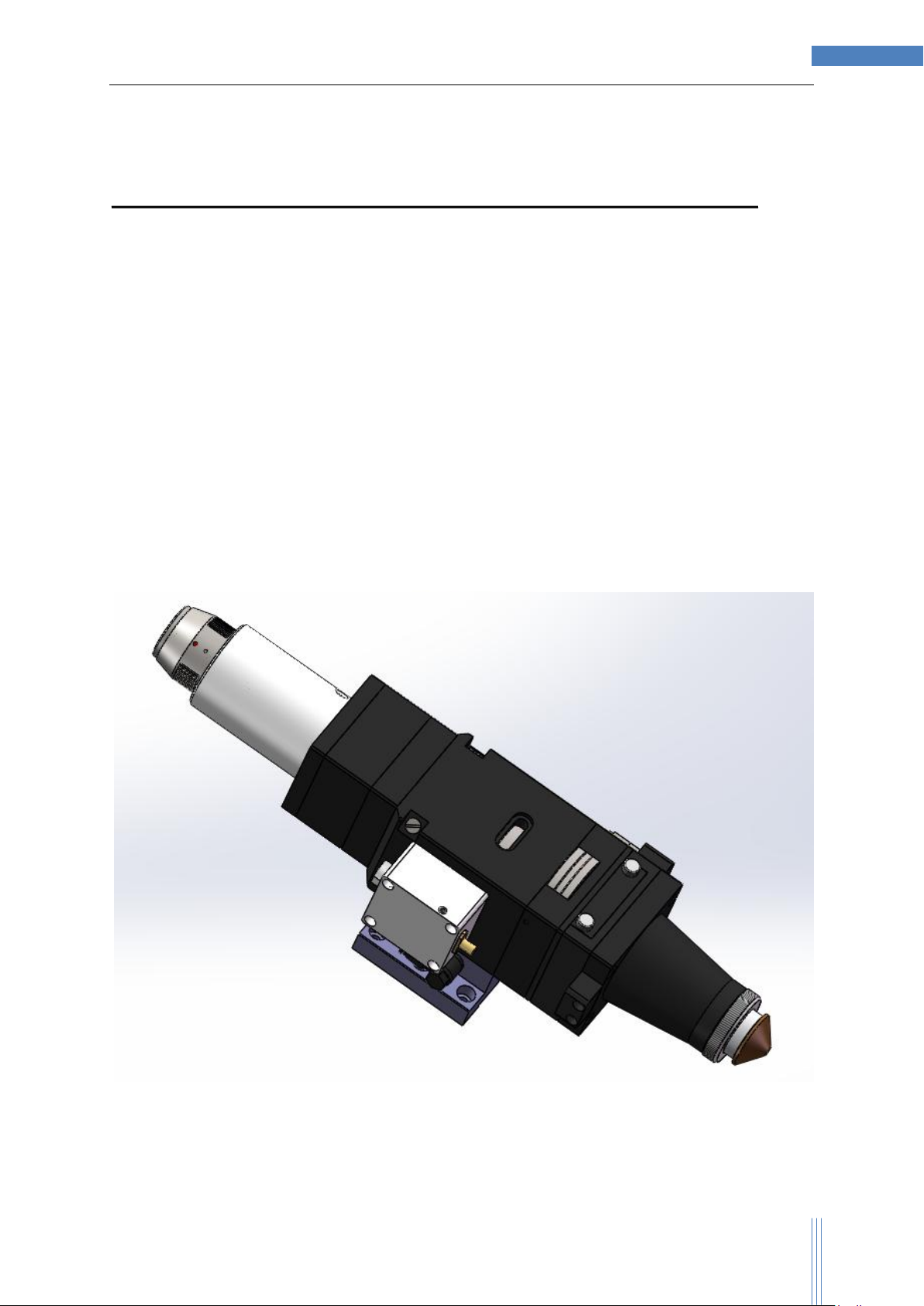
C4 series flat-bed cutting head is a kind of fiber laser cutting head suitable for median to high
power. It can cut stainless steel of maximum thickness 7 mm and carbon steel of maximum
thickness 15 mm with best cutting quality. It features with water cooling and draw design for
protective windows. Fiber interface is available with only QBH connector. Best support 1000W to
2000W application.
Fiure1-1 Product Appearance

Copyright © AU3TECH RESEARCH PTY LTD
C4 Cutting head Users Manual By Au3tech Research Pty Ltd
5
1.2 Product Features
Support multiple kinds of focal length (125mm, 150mm)
Support multiple kinds of fire-optic link (QBH, QD)
Focus module design with high-precision
Centering control module design with precision
Protection lens box can be quickly disassembled
Optimized smooth gas circuit design; multiple kinds of auxiliary gases; the maximum
atmosphere pressure can reach 2.5MPa
1.3 Cutting head parameters
Since different cutting heads have different focal lengths and optical chucks, the following
parameters are described with chuck QBH and focal lengths 125mm as an object. For other
configuration parameters, please connect the technical engineers ofAut3tech.
Maximum power
1500W
Focal length
125mm, 150mm
Collimation focal length
75mm, 100mm
Diameter of focus lens
30mm
Nozzle aperture
1mm to 3mm
Length of cutting head
341mm@FL=125mm
Weight
2.6KG@FL=125mm
Maximum atmosphere pressure of auxiliary gas
2.5MPa
Maximum outer diameter
64mm
Available focusing ranges
-6mm to +9mm
Type of optical fiber splice
QBH
Copyright © AU3TECH RESEARCH PTY LTD
C4 Cutting head Users Manual By Au3tech Research Pty Ltd
6
2Structure Specifications
2.1 C4 Fiber laser cutting head brief
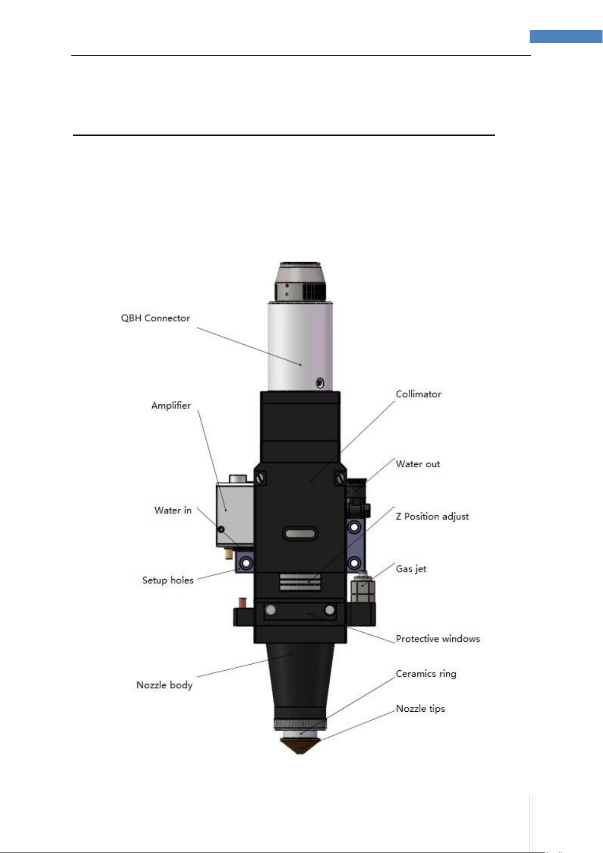
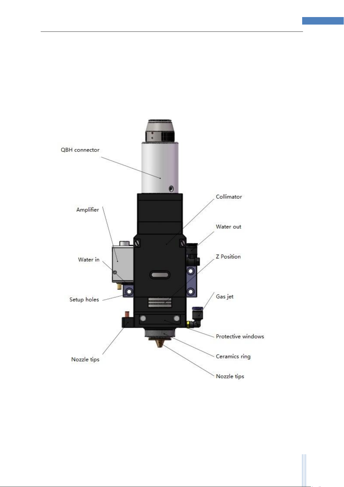
C4 fiber laser cutting are designed for flatbed cutting, 3D cutting and fine cutting.
2.1.1 C4 flatbed cutting head

Copyright © AU3TECH RESEARCH PTY LTD
C4 Cutting head Users Manual By Au3tech Research Pty Ltd
7
2.1.2 C4 3D cutting head
C4 3D series is designed for 3D cutting. It comes with longer focus length than normal flat-bed
cutting heads. In term of larger aperture and longer focus length, the depth of focus can achieve
longer than usual, so the cutting curve can be better quality. The tip of the head is small and
straight for 3D or tube cutting.
Copyright © AU3TECH RESEARCH PTY LTD
C4 Cutting head Users Manual By Au3tech Research Pty Ltd
8
2.1.3 C4 fine cutting head
C4-FC series is designed for fine cutting. It comes with shorter focus length than normal flat-bed
cutting heads or 3D cutting heads. In term of larger aperture and short focus length, the focus
spot can achieve smaller and it is better for thin metal cutting.

Copyright © AU3TECH RESEARCH PTY LTD
C4 Cutting head Users Manual By Au3tech Research Pty Ltd
9
3Installations
3.1 Pre-installation preparation
Before installing C4 cutting head, please ensure fiber-optic chuck is sealed and during
installation, never remove sealing.
Table 3-1 List of Tool Preparation
Name of Tool
Picture
Main Functions
No.3 socket head
wrench
Backboard of cutting head connects slipway
No.2 socket head
wrench
Focus lens center
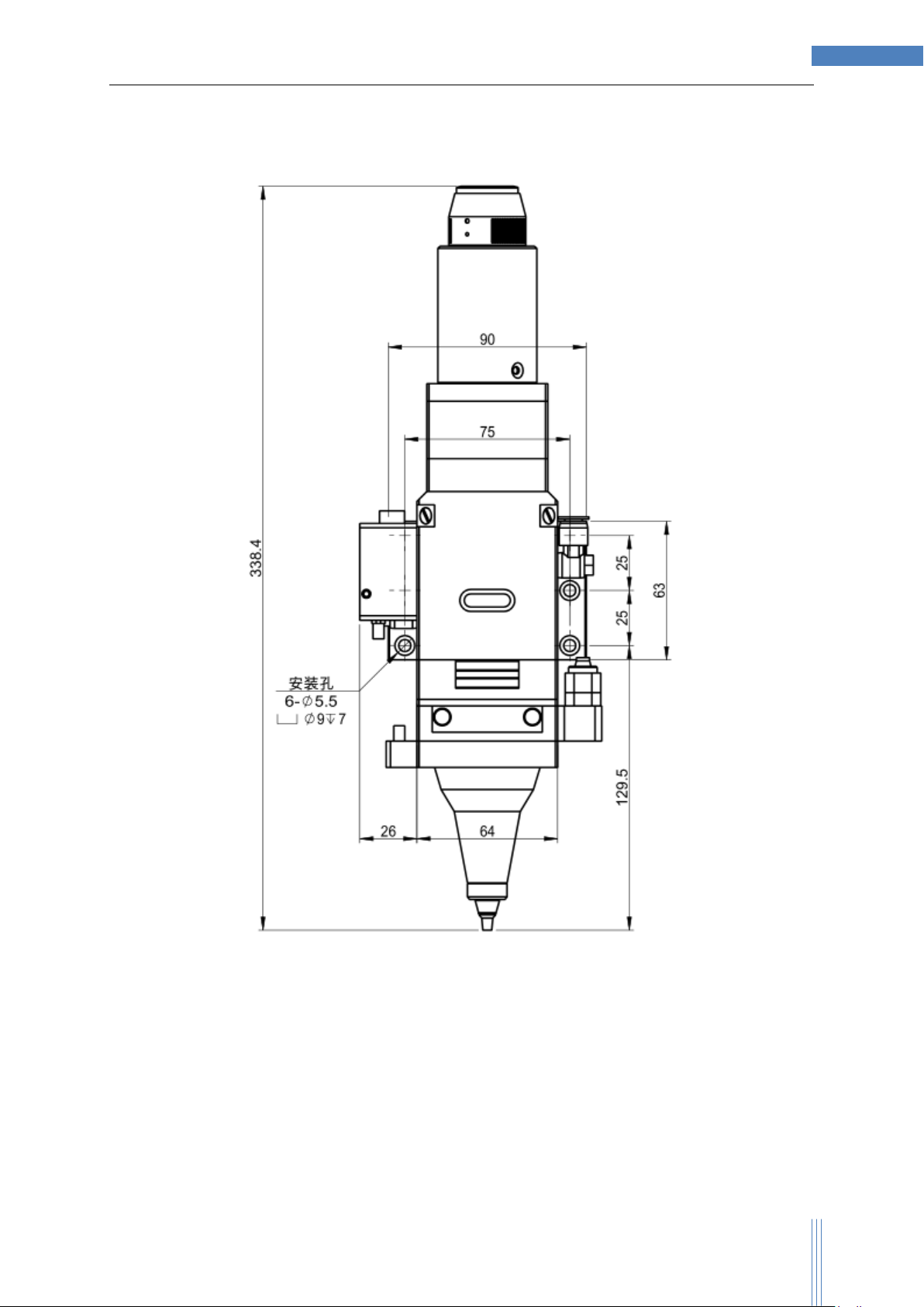
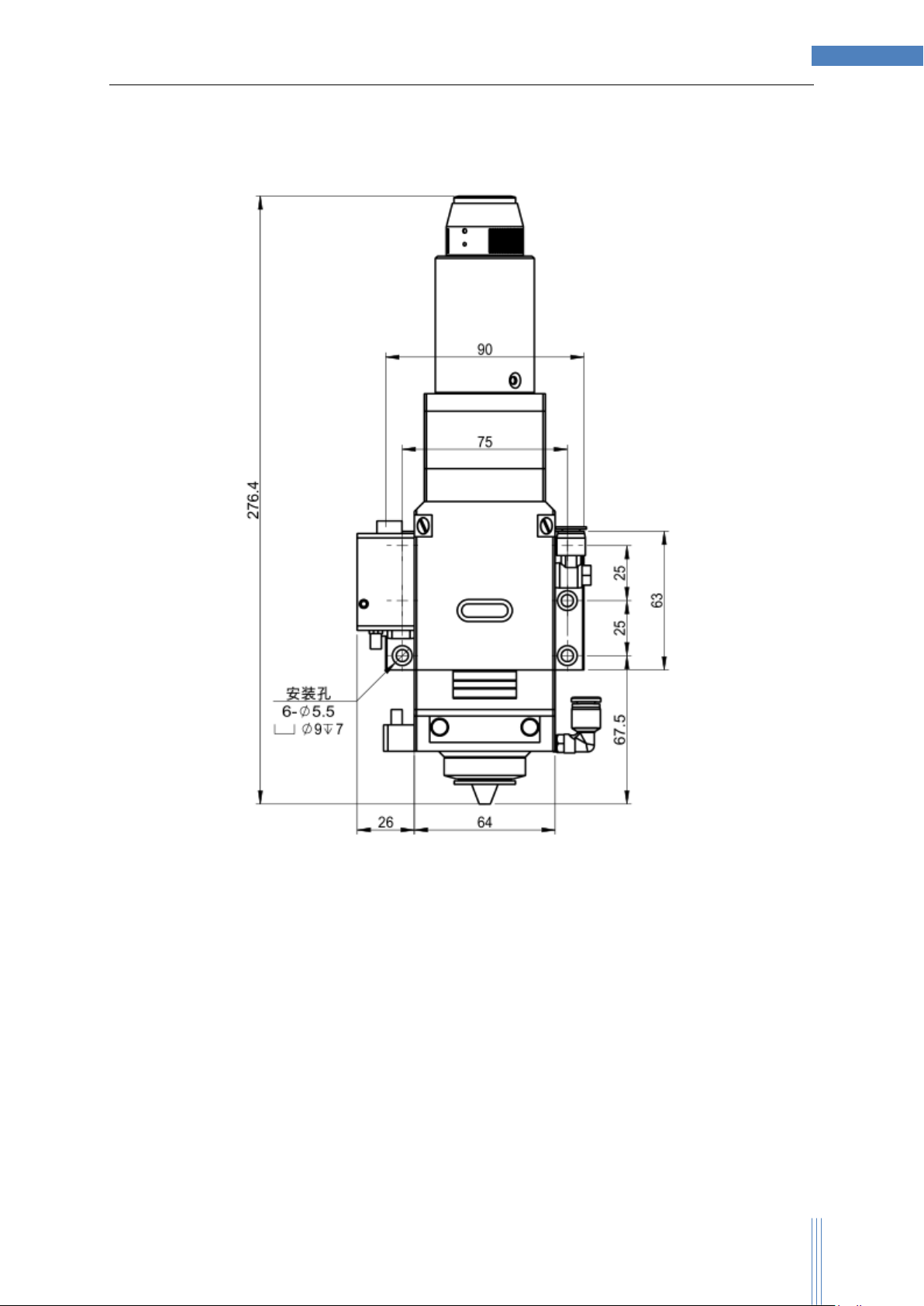
3.2 Installation Dimension of Cutting Head
Cutting head and machine tool are fixed by dead plates. On the backboard, there are six M5
fixing holes. Just as shown in the figure, when installing, tight up the corresponding position of
screw and Z-axis link block of machine tool; at the same time, installation position can be
adjusted according to customer requirements.

Copyright © AU3TECH RESEARCH PTY LTD
C4 Cutting head Users Manual By Au3tech Research Pty Ltd
10
3.2.1 C4-QBH100-F125 and C4-QBH100-F150
(Contact us for more details)
Copyright © AU3TECH RESEARCH PTY LTD
C4 Cutting head Users Manual By Au3tech Research Pty Ltd
11
3.2.2 C4-3D-QBH100-F125
(Contact us for more details)
Copyright © AU3TECH RESEARCH PTY LTD
C4 Cutting head Users Manual By Au3tech Research Pty Ltd
12
3.2.3 C4-FC-QBH100-F50
(Contact us for more details)

Copyright © AU3TECH RESEARCH PTY LTD
C4 Cutting head Users Manual By Au3tech Research Pty Ltd
13
3.3 Tube connection of C4 Process Head
C4 laser process head adopts the design of optical lens surrounded by water-cooling, which can
reduce the chance of lens damage by heat effectively and restrain the deformation of lens
caused by heat effect in the long operation.
In the following table, the detailed water-cooling environment that C4 process head needs is
provided:
Minimum flow rate
1.5L/min
Recommended flow rate
2.0 L/min
Recommended flow rate hydraulic
pressure
1.8 bar
Recommended temperature
15~35℃(above the temperature of moisture
condensation of environment)
Type of running water
Purified water
Connection type
Quick-inserting water pipe joint with diameter 6mm

Copyright © AU3TECH RESEARCH PTY LTD
C4 Cutting head Users Manual By Au3tech Research Pty Ltd
14
3.4 QBH Connection
Operation sequence:
1. Take down the plastic protective cap at the top of link block.
2. Align the small hole on the QBH to the small hole on the link block, red dot to red dot,
insert QBH until the end.
3. Tighten up the set screw nut clockwise, just as shown in the figure.
4. Lift up the set screw nut and Tighten up it clockwise again.

Copyright © AU3TECH RESEARCH PTY LTD
C4 Cutting head Users Manual By Au3tech Research Pty Ltd
15
4Focus Adjustments
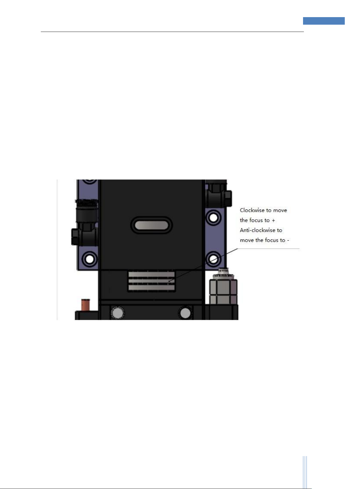
4.1 Focus centering
The centering of all C4 fiber cutting head series are finished by the two adjusting screws just as
shown in the following figure. When centering, No. 2.5 socket head wrench is used. Clockwise
adjustment makes focus move to the direction of backboard and counterclockwise adjustment
makes focus move to the opposite direction. There are a total of two adjusting screws. The first
calibration is made before delivery, and when using, only a slight readjustment is needed.
Copyright © AU3TECH RESEARCH PTY LTD
C4 Cutting head Users Manual By Au3tech Research Pty Ltd
16
4.2 Z position adjustments
The Z-axis position adjustment of all C5 fiber cutting head series are finished by the hand wheel
unit just as shown in the following figure. Clockwise adjustment of hand wheel makes focus
extend and counterclockwise adjustment of hand wheel makes focus shorten. When delivery, the
focus is placed the standard position from the nozzle 1mm and can be used for most cutting.
The moving ranges of focus lens are“0~8mm”. When it is adjusted to “0”, focus is at the nozzle
nearby (since focus lens has errors). When it is adjusted to “+4”, focus extends furthest away
from the nozzle and When it is adjusted to “-4”, focus has the most retraction into the nozzle.
Copyright © AU3TECH RESEARCH PTY LTD
C4 Cutting head Users Manual By Au3tech Research Pty Ltd
17
5Operation &Maintenance
5.1 Maintenance of Protective windows
Protective window is at the bottom of focusing module. When lens sticks to impurities or foreign
matters, they cause damage to lens. Therefore, regular maintenance of window is needed. It is
suggested to clean it once a week. As for the structure of windows, please refer the figure below.
Protective windows are vulnerable parts and in case of damage, we need to replace it. During
maintenance/replacement, be sure to wear dust-proof gloves or finger stall so as to avoid the oil
stain and dust on hand from polluting lens.
5.1.1 Taking out of windows
Wear dust-proof gloves or finger stall; counterclockwise loosen the two set screws at the red
protective lens drawer; draw out protective lens slowly and steadily; move it to clean and tidy
indoor.
5.1.2 Disassembly of windows
1. Put the side with seal ring adown and hold lens base with left hand.

Copyright © AU3TECH RESEARCH PTY LTD
C4 Cutting head Users Manual By Au3tech Research Pty Ltd
18
2. Gently squeeze the edge of the windows with right thumb from the top down (Note: be sure to
squeeze the edge, since squeezing the center cannot make the windows fall off), place the
index finger of right hand on the opposite direction of thumb so as to protect the lens from
slipping.
3. Keep on pressing down gently with thumb until seal ring and the lens fall off.
5.1.3 Clean Lens
A. Tools: dust-proof gloves/finger stall, continuous fiber absorbent cotton swab, isopropanol and
rubber air-blower.
B. Cleaning methods:
1. Wear finger stall on thumb and index finger of left hand.
2. Spray isopropanol onto fiber degreasing cotton swab.
3. Gently hold the edge of the side face of protective lens with thumb and index finger of left hand.
Notes: finger stall cannot touch the surface of lens to avoid leaving a mark.
4. Make the lenses directly face eyes, hold fiber absorbent cotton well with right hand, from left to
right or from down to up, gently clean the lens with the single direction (Never rub backwards and
forwards so as to avoid secondary pollution to lens), and blow the lens surface with rubber air-
blower. Both sides should be cleaned. After cleaning, it should be ensured that there is no any
following residue: detergents, absorbent cotton, foreign bodies and impurities.
Notes: after cleaning, the lens can't be exposed in the air, it should be installed as soon as
possible according to the method shown in 5.1.4 or temporarily kept in dry clean sealed container.

Copyright © AU3TECH RESEARCH PTY LTD
C4 Cutting head Users Manual By Au3tech Research Pty Ltd
19
5.1.4 Front and back side are irrespective for the installation of
protective lens since both sides are plane.
1. Place protective lens base, lens, seal ring from bottom to top in turn, and compact them just as
shown in figure.
2. Refill into the bottom of lens module, and clockwise tighten the set screw by hand
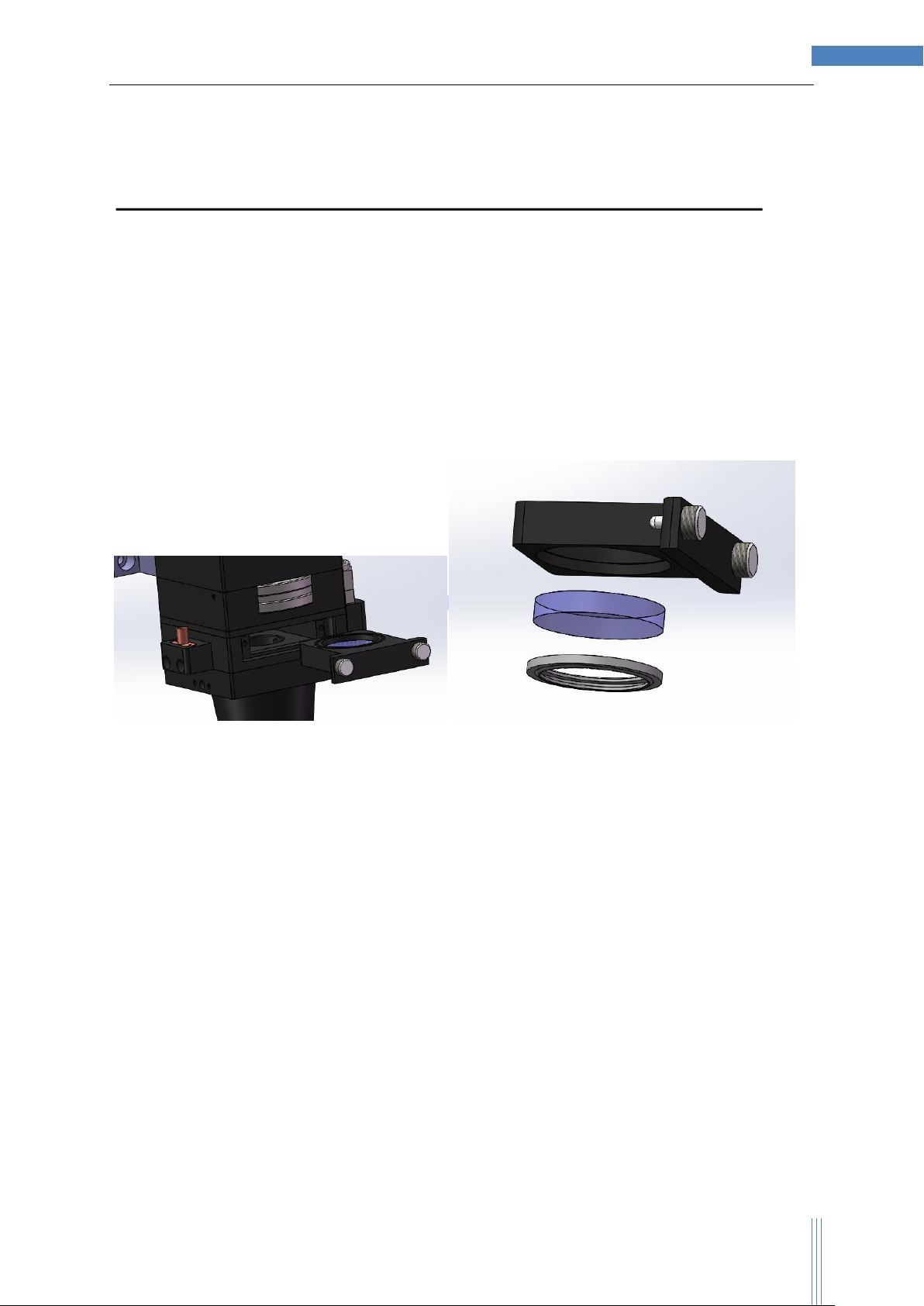
5.2 Collimator and focus lens maintain
C4 fiber laser process head has excellent leak tightness, so regular inspection of its population is
unnecessary. But if the machine tool is frequently moved, the cleanness of the lens should be
inspected in the dust-free room before pulling in or pulling out fiber and re-installation
All collimators and focus lens come in holders, so it is much easier to get it replaced.
5.2.1 Take out of lens holder
First unload the 4 M3 socket head screws shown in above figure with socket head wrench,
wear dust-proof gloves/finger stall, loosen the XY adjusting screw and take out lens holder and
replace it.
5.2.2 Assemble the lens holder

Copyright © AU3TECH RESEARCH PTY LTD
C4 Cutting head Users Manual By Au3tech Research Pty Ltd
20
After finishing cleaning the lens by the steps of cleaning protective lens, wear dust-proof
gloves/finger stall, back-step by the steps of taking out lens and install the focusing lens well. Be
sure the plane of the lens adown during installation.
Table of contents
Other Au3Tech Industrial Equipment manuals

Popular Industrial Equipment manuals by other brands

GCC Technologies
GCC Technologies Laser Pro DFS Installation & operation manual

PROTRAKKER
PROTRAKKER 400DB owner's manual

TMG
TMG TMG-AB72 product manual

GSI Group
GSI Group X Series Sweep Operator's manual

Cascade TEK
Cascade TEK SVO-5-VC Installation and operational manual

Mannesmann Demag
Mannesmann Demag ESR AX25 Series installation instructions


