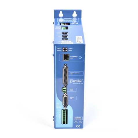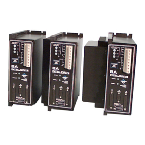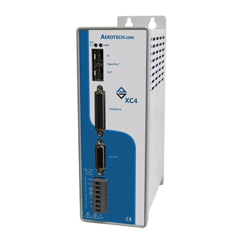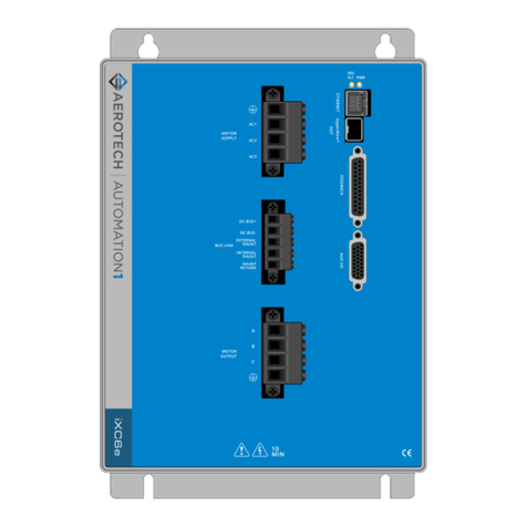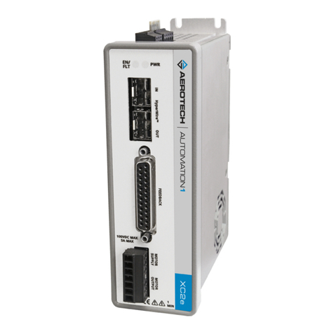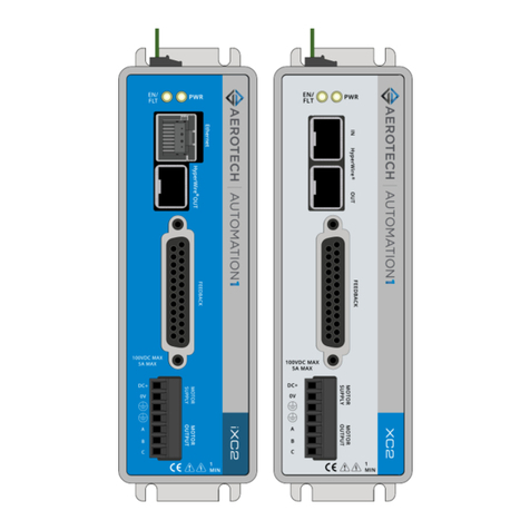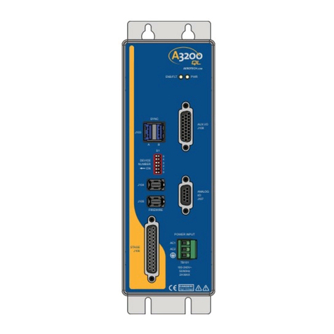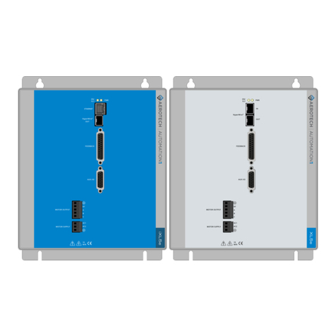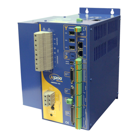
Ndrive HL User’s Manual Table of Contents
www.aerotech.com iii
TABLE OF CONTENTS
CHAPTER 1: INTRODUCTION ................................................1-1
1.1. Feature Summary .....................................................................1-2
1.2. Connection Overview................................................................1-3
1.3. Ndrive HL Block Diagram..........................................................1-4
1.4. Ordering Information .................................................................1-5
1.5. Electrical Specifications ............................................................1-6
1.6. Mechanical Specifications.........................................................1-9
1.7. Environmental Specifications..................................................1-10
CHAPTER 2: INSTALLATION and CONFIGURATION ..............2-1
2.1. Safety Procedures and Warnings .............................................2-1
2.2. Power Connections...................................................................2-2
2.2.1. Control Power Connections (-AUXPWR) ....................2-2
2.2.2. Motor Power Connections ...........................................2-3
2.2.3. Motor Connections (TB101).........................................2-4
2.2.4. I/O and Signal Wiring Requirements ...........................2-4
2.3. Emergency Stop Sense Input (TB201) .....................................2-5
2.3.1. Typical ESTOP Interface .............................................2-6
2.4. Motor and Feedback Connections............................................2-7
2.4.1. DC Brush Motor in Torque Mode Configuration ..........2-7
2.4.2. DC Brush Motor with Tachometer Feedback
Configuration................................................................2-8
2.4.3. Brushless Motor Configuration ....................................2-9
2.4.4. Stepper Motor Configuration......................................2-14
2.5. Encoder Feedback Connections.............................................2-15
2.5.1. Encoder Phasing........................................................2-16
2.6. End of Travel (EOT) Limit Input Connections .........................2-17
2.6.1. End of Travel (EOT) Limit Phasing ............................2-17
2.7. Communication Channel Settings ..........................................2-18
2.8. Connecting Multiple Ndrive HLs .............................................2-19
2.9. PC Configuration and Operation Information..........................2-20
CHAPTER 3: TECHNICAL DETAILS....................................... 3-1
3.1. Auxiliary I/O Connector (J205)..................................................3-1
3.1.1. Secondary Encoder Channel (J205)............................3-3
3.1.2. User Outputs 8-11 (J205) ............................................3-4
3.1.3. User Inputs 8-11 (J205) ...............................................3-5
3.1.4. High Speed User Inputs 12-13 (J205) .........................3-6
3.1.5. Analog Input 0 (J205)...................................................3-6
3.1.6. Analog Output 0 (J205)................................................3-6
3.2. Position Synchronized Output (PSO) / Laser Firing .................3-7
3.2.1. Single Axis Laser Firing .............................................3-11
3.3. Motor Feedback (J207)...........................................................3-12
3.3.1. End of Travel Limit Inputs ..........................................3-13
3.3.2. Hall-Effect and Thermistor Inputs ..............................3-14
3.3.3. Brake Output..............................................................3-15
3.3.4. Encoder Interface.......................................................3-15
3.4. RS-232 / RS-422 Port (J206)..................................................3-20
3.5. FireWire Bus (J201, J202, J203) ............................................3-22
Artisan Technology Group - Quality Instrumentation ... Guaranteed | (888) 88-SOURCE | www.artisantg.com

