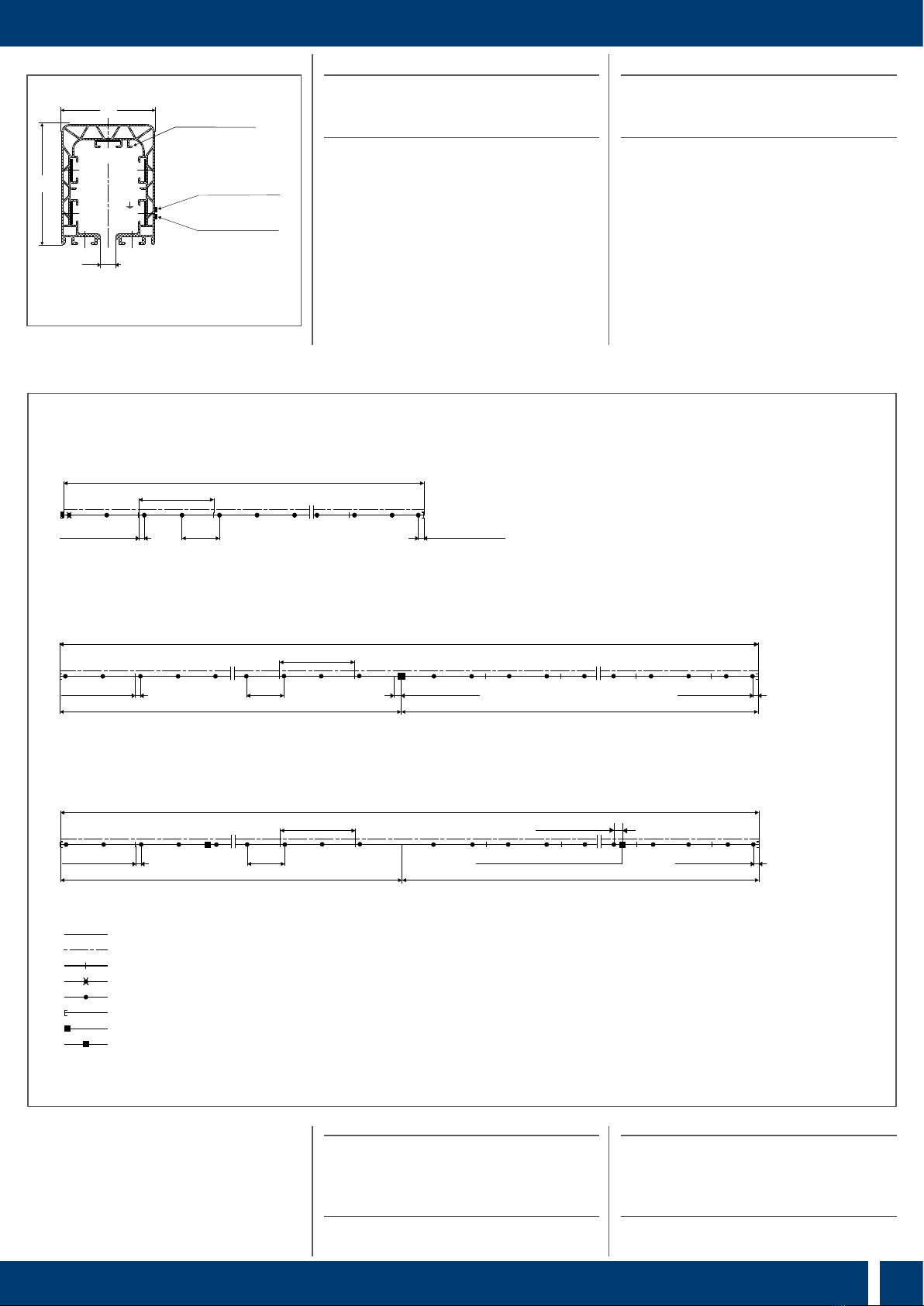
KBH Montageanleitung Mounting instructions
54
70
Sicherheits-Steg
safety lip
gelb (dunkelgrau)
yellow (dark grey)
grün (dunkelgrau)
green (dark grey)
9
L1
(2)
L2
(1)
L3
(4)
(3)
( )Kennzeichnung bei Steuerleitung
( )for control circuits
1
2
G
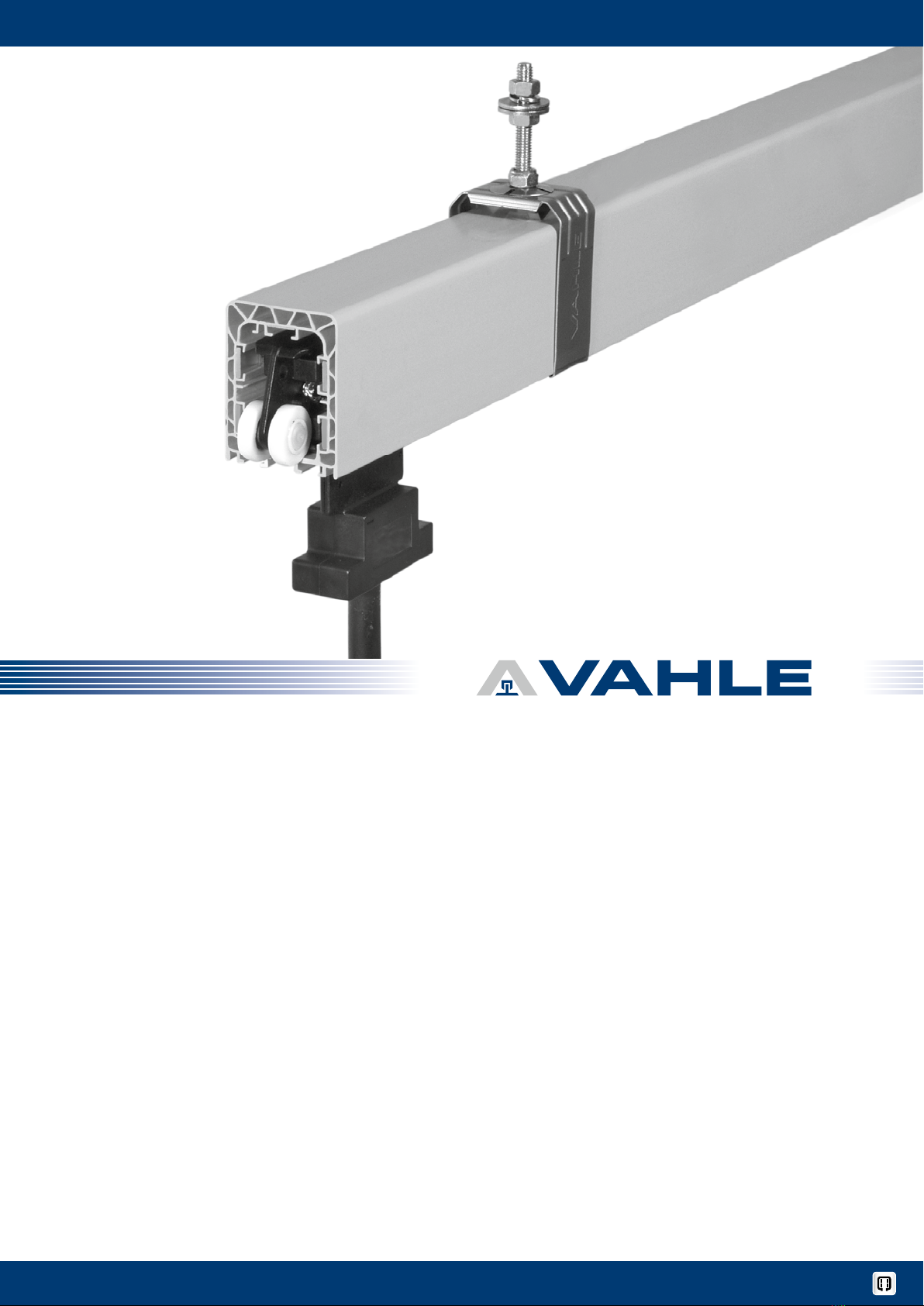
Schleifleitungen montieren
Halteeisen anbringen
Schraubkonsolen oder Winkeleisen mit
Langlöchern anbringen.
HFolgenden Montage-Abstände
beachten:
Aufhängeabstand max. mm für
Innenanlagen und überdachte Aus-
senanlagen mit einer Umgebungs-
temperatur bis °C. Max. mm
für Aussenanlagen, spez. Innenanla-
gen mit hohen Umgebungstempera-
turen (>–°C) und Anlagen mit
Beheizung. Die erste und letzte Auf-
hängung ist mind. mm und max.
mm vom Teil stückende anzuord-
nen. Der Abstand der Gleitaufhängun-
gen von dem Verbindungsmaterial,
den Endkappen, Einspeisungen usw.
muss mindestens mm bis max.
mm betragen, um die Ausdeh-
nung nicht zu behindern (G02).
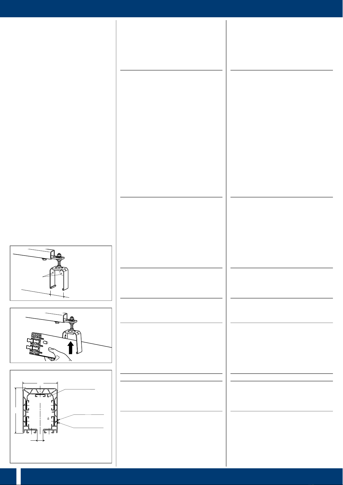
Schleifleitung aufhängen
Die beiliegenden Unterlegscheiben an den
Aufhängebolzen der Fest- und Gleitaufhän-
gungen nur bei der Montage in Langlöchern
verwenden.
Gleitaufhängungen an den Konsolen be-
festigen (G03).
SDie Schenkel der Gleitaufhängung
müssen senkrecht nach unten und
mit einem Zwischenmaß von < mm
sein (bei Bedarf nachrichten) (G03).
Schleifleitungen von unten in die Gleitauf-
hängungen schieben (G04).
SDie Schleifleitungen müssen mit
den unteren Stegen in den zwei U-
förmigen Umgreifungen der Gleitauf-
hängungen liegen. Auf durchgehend
gleiche Anordnung der Kennzeich-
nungsstreifen und Sicherheitsstege
achten (G05).
H
Der Aufnahmebügel der Gleitaufhän-
gung ist drehbar gelagert und stellt
sich bei der Montage in Längsrichtung
zur Schleifleitung ein.
Installation of powerails
Mounting of support brackets
Bolt EHK standard brackets or weld steel
angles with slotted holes.
HObserve the following installation
distances:
Max. support distance mm for
indoor and roofed outdoor installa-
tions with a ambient temperature up-
to °C). Max. mm for outdoor
installations, special indoor systems
with high ambient temperatures (>–
°C) and systems with heating. The
first and last hanger must be placed
at least mm and no more than
mm from the end of a powerail
section. The distance of the sliding
hangers from the joint material, end
caps, feed points, etc. must measure
at least mm and up to mm
to guarantee free expansion (G02).
Installation of powerail
Use the supplied washers at the support
bolts of the fixpoint and sliding hangers
only for installation in slotted holes.
Attach the sliding hangers at the brack-
ets (G03).
SThe branches of the sliding hanger
must be vertical and down with an
intermediate measure of < mm
(realign, if necessary) (G03).
Push the Powerails from the bottom into
the sliding hangers (G04).
S
The powerails must be located in the
two U-shaped webs of the sliding
hangers with the two lower lips.
Ensure continuous uniform ar-
rangement of the identifica-
tion strips and safety lips (G05)
HThe mounting brackets of the slid-
ing hanger is rotatable and adjusts
itself in longitudinal direction to the
powerail during installation.
< 50 mm
< 90°
G
G