manuals.online logo
Brands
  1. Home
  2. •
  3. Brands
  4. •
  5. Spectra
  6. •
  7. Industrial Equipment
  8. •
  9. Spectra DG211 User manual

Spectra DG211 User manual

Popular Industrial Equipment manuals by other brands

ABB Unifix AD Instruction handbook

ABB

ABB Unifix AD Instruction handbook

Mark 7 Evolution user manual

Mark 7

Mark 7 Evolution user manual

Husky HyPET Original instructions

Husky

Husky HyPET Original instructions

bora PM-1800 user manual

bora

bora PM-1800 user manual

Grizzly T32428 owner's manual

Grizzly

Grizzly T32428 owner's manual

Siemens 8MF1 Series operating instructions

Siemens

Siemens 8MF1 Series operating instructions

ABB HT610965 Operation manual

ABB

ABB HT610965 Operation manual

ABB SafeLink Installation and operating instructions

ABB

ABB SafeLink Installation and operating instructions

Phoenix PHX-150 user guide

Phoenix

Phoenix PHX-150 user guide

ABB A165-L32 Operation manual

ABB

ABB A165-L32 Operation manual

ABB HT842936 Operation manual

ABB

ABB HT842936 Operation manual

Hermetica 10 Series user manual

Hermetica

Hermetica 10 Series user manual

HORNER OEE Solution manual

HORNER

HORNER OEE Solution manual

Hammerhead HG375 parts manual

Hammerhead

Hammerhead HG375 parts manual

SCHUNK VERO-S NSE-A3 138 Assembly and operating manual

SCHUNK

SCHUNK VERO-S NSE-A3 138 Assembly and operating manual

ABB HT566657 Operation manual

ABB

ABB HT566657 Operation manual

Webasto GSE CAN installation guide

Webasto

Webasto GSE CAN installation guide

ABB HT614003 Operation manual

ABB

ABB HT614003 Operation manual

manuals.online logo
manuals.online logoBrands
  • About & Mission
  • Contact us
  • Privacy Policy
  • Terms and Conditions

Copyright 2025 Manuals.Online. All Rights Reserved.

DG211
spectraprecision.com
User Guide
Bedienungsanleitung
Manuel de l´utilisateur
Guida per l´uso
13
15
14
16
17 18
19
20
1
35 4
6
8
2
9
10 11
12
7
16 16
16
16 18
21
22
Exit of Laser Beam
25
26 27
28
24
1
2
3
5 4
6
8
7
23
RC201
946
4
5
Contents
1 Introduction ................................................................................ 6
2 Safety Instructions .................................................................... 6
3 Product........................................................................................ 7
3.1 General Description ............................................................ 7
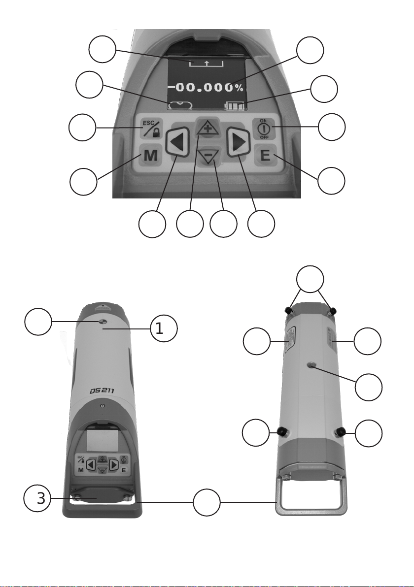
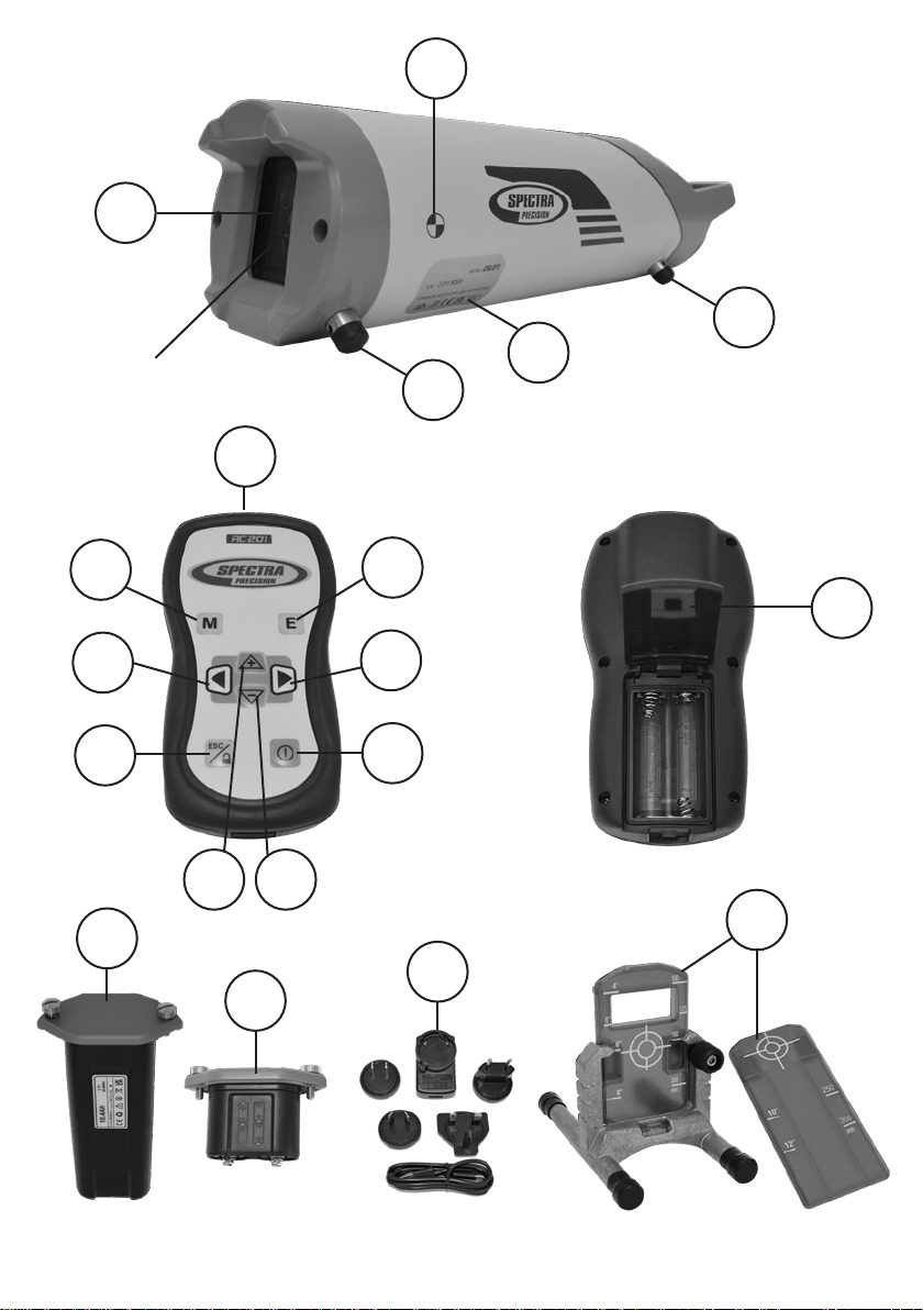
3.2 Product Components .......................................................... 8
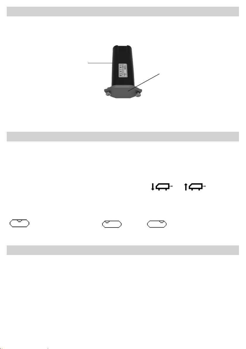
3.3 Installing The Batteries ...................................................... 9
3.4 Battery Status Indication................................................... 9
3.5 Recharging The Batteries................................................... 19
3.6 Battery Door ........................................................................ 10
3.7 Laser Setup .......................................................................... 10
3.8 Turn On/O The Laser ........................................................ 10
3.9 Grade Entry With Digit Select Mode ................................. 11
3.10 Grade Entry With Step & Go Mode .................................... 11
3.11 Laser Alignment................................................................... 12
3.12 Center Laser......................................................................... 12
3.13 Manual Mode........................................................................ 12
3.14 Lock Keypad ......................................................................... 13
3.15 Roll Alert............................................................................... 13
3.16 Standby Mode...................................................................... 13
4 Check Calibration....................................................................... 14
4.1 Check Level Accuracy ......................................................... 14
4.2 Check Grade Accuracy........................................................ 15
5 Cleaning And Maintenance ....................................................... 16
6 Protecting The Environment..................................................... 16
7 Warranty...................................................................................... 17
8 Technical Specication.............................................................. 18
8.1 Technical Specication Laser DG211................................. 18
8.2 Technical Specication Remote Control RC201 .............. 18
9 CE Declaration Of Conformity .................................................. 19
10 UKCA Declaration Of Conformity............................................. 19
11 Service And Customer Advice .................................................. 19
6
1 Introduction
Thank you for choosing a Spectra Precision pipe laser. The pipe laser is an easy-to-
use tool that provides underground contractors line, elevation, and grade control for
installing storm, sanitary, or other gravity-ow pipe. This system can also be used for
tunneling, boring, pipe alignment, or any other application requiring line, elevation, and
grade control.
The pipe laser projects a highly visible laser beam in a direction at a predetermined
(grade) for the alignment of gravity-ow pipe.The laser light is intercepted by a target.
To align the pipe, you need toposition it so that the pipe laser’s beam is centered at the
target’s bullseye.
2 Safety Instructions
For hazard-less and safe operation, read all the user guide instructions.
• Use of this product by people other than those trained on this product may result
in exposure to hazardous laser light.
• The users of this product ensure they have read and understand the user guide.
• Do not remove warning labels from the unit.
• The DG211 is class 3A/3R laser (<5mW; 600 – 680nm) IEC 60825-1:2014.
A Class 2 version is also available.
• Never look into the laser beam or direct it to the eyes of other people.
• Always operate the unit in a way that prevents the beam from getting into people’s
eyes.
• If initial service is required which results in the removal of the outer protective
cover, removal must only be performed by factory-trained personnel.
• Do not use the product in aggressive or explosive environment.
• Ensure that product is not damaged so that any unsafe usage is prevented.
• Before starting your work, always check the leveling accuracy of the product. See
chapter 4.1.
• Spectra Precision is not responsible for any inaccuracy that is caused by not
reading the user guide and by any misuse of the product.
• The user of the product is responsible to check the results for accuracy.
• Never put a wet laser or wet accessories in the carrying case for storage.
7
Caution: Use of other than the described user and calibration tools or other
procedures may result in exposure to hazardous laser light.
Caution: Using the laser dierently than described in the user guide may result in
unsafe operation.
Note: Any local or national laws and regulations for the use of machines or
products described in this document must be followed.
Note: Reections from some surfaces like windows or at metal surfaces can
lead to wrong receiver readings.
Note: After storage or transportation, let the product acclimate to the ambient
temperature before use of high accurate measurements.
Note: Do not expose the unit to extreme temperatures or extreme temperature
changes (do not leave in vehicles).
Warning: Li-Ion batteries or alkaline batteries shipped with the product may
contain small amounts of harmful substances.
Do not open the battery, dispose of in re or short circuit; it may ignite,
explode, leak or get hot causing personal injury.
Dispose of batteries in accordance with all applicable federal, state and
local regulations.
Keep the batteries away from children, If swallowed, do not induce
vomiting. Seek medical attention immediately.
Charge only with specied chargers according to device manufacturer’s
instructions.
Be sure to charge the battery before using it for the rst time and after
not using it for an extended length of time.
Do not open the rechargeable batteries cage.
3 Product
3.1 General Description
The laser ships with a rechargeable Li-Ion battery pack. Alkaline batteries can be used
as a backup to power the laser at the job site. When alkaline batteries are used, the
plus and minus symbols in the battery pocket indicate how to install the batteries into
the product.
The rechargeable Li-Ion battery pack avoids mis-insertion by design.
Note: Charging the rechargeable Li-Ion battery pack beyond the temperature
mentioned in the technical specication (chapter 8.1) may lead to decreased battery
life or undercharged batteries.
8
3.2 Product Components
DG211 Laser and RC201 Remote Control
1Power Button
Press DG211 for one second to turn on the Laser;
press and hold for one second to turn o the laser
2 E – Button Enter button; conrms the grade entry
3 Arrow Button Right Moves beam or cursor to the right
4 Minus Button Decreases grade value or moves beam down
5 Plus Button Increases grade value or moves beam up
6 Arrow Button Left Moves beam or cursor to the left
7 M – Button Changes to grade enter mode or manual mode
8 ESC/Lock Button
9Roll Vial Shows roll position of the product housing
10 Laser Beam Position Symbol shows the position of the laser beam
11 Grade Display Shows the current grade value
12 Battery Symbol Shows the amount of battery charge
13 Laser Battery Door with
Thumbscrews
Opens the battery compartment to remove or
replace the batteries
14
Line-Axis Pivot Marker and
LED
Point where the alignment directions starts; when
powering the laser on, the LED is on for 15 minutes
before it switches o automatically
15 Axis Alignment Markers Markers help to align the product
16 Legs Legs; dierent sets available
17 Laser Safety Label Shows laser warning information
18 Serial Number Label
19 Tripod Mounts 5/8x11 Mount to tripod
20 Handle Product carrying handle
21 Beam Exit Windows Exit of the laser beam
22 Grade Axis Pivot Marker Point where the grade starts
23 RC201 Infrared Diodes Emitting of IR light
24 RC201 Battery Door Open to insert or replace batteries
25
Li-Ion Battery Pack
and Battery Door with
Thumbscrews
26 Alkaline Spacer with
Battery Door
27 CH11 Charger
28 946 Target Set
9
3.3 Installing the Batteries
Open the battery door using the turning knobs.
Rechargeable: Insert the rechargeable battery pack. It is designed to only be inserted
one way and prevents mis-insertion.
Note: DO NOT REMOVE RECHARGEABLE BATTERIES FROM THEIR CAGE AND
INSTALL
ALKALINE BATTERIES. SEVER DAMAGE TO THE UNIT WILL RESULT IF
CHARGING IS ATTEMPTED.
The Li-Ion battery pack is charged outside the unit.
When needed replace Li-Ion battery pack with alkaline batteries using the alkaline spacer.
Alkaline: Four C-cell alkaline batteries can be used as a backup.
Insert four C-cell alkaline batteries into the housing according to the symbols within
the battery compartment and on the alkaline spacer.
Close the battery door.
3.4 Battery Status Indication
The approximate charge of the batteries is shown in the LCD (12). The remaining
battery lifetime is depending on the battery brand, the temperature, the job site
conditions (wind, vibrations, etc.) as well as age of the batteries and amount of
recharge cycles.
battery good; no need to charge.
battery low; user can still use the product.
battery empty; charge battery to avoid abnormal product behavior.
3.5 Recharging the Batteries
For charging the Li-Ion battery pack (25), connect the charger (27) with the Li-Ion
battery pack using the USB charging cable. It takes approximately 6 hours to charge
the Li-Ion battery pack.
Charging Indicator LED: O - Not Charging
Blinking - Charging
On - Charging Complete
When the charger is unplugged, the LED will remain on for approximately one minute.
Note: See chapter 8.1 for the temperature range for charging the Li-Ion battery pack.
LED
10
3.6 Battery Door
To remove the battery door from the alkaline spacer or from the Li-Ion battery pack,
hold either the alkaline spacer or the Li-Ion battery pack and turn the battery door 90°
counterclockwise.
To mount the battery door to the Li-Ion pack or the alkaline spacer, do the same steps
as mentioned above turning the battery door 90° clockwise.
3.7 Laser Setup
Position the laser at the manhole invert or on bottom of the trench at the desired
elevation.
It is required to position the laser within its self-leveling range; see chapter 8.1.
When the laser is not positioned within the self-leveling range, the laser beam will
drive towards the maximum position and the symbol or will blink,
indicating to lower or raise the handle to achieve the self-leveling range.
For the correct cross axis position, the LCD window shows the correct position with
the roll vial symbol (9). For correct grade the symbol has to be in the center position
. If the symbol is in the left or right position the laser
accuracy will be aected.
3.8 Turn On/O Laser
Press the power button (1) on the laser for one second to turn on the laser. The display
turns on and the self-leveling will start at once with the last saved grade value. The line
axis LED (14) powers on for 15 minutes.
During self-leveling the laser beam and the % symbol blink. The laser has completed
leveling when the laser beam and the % symbol in the LCD display are no longer
blinking.
Battery Door
Li-Ion Battery Pack