manuals.online logo
Brands
  1. Home
  2. •
  3. Brands
  4. •
  5. AUDAC
  6. •
  7. Amplifier
  8. •
  9. AUDAC R1 Installation and operating instructions

AUDAC R1 Installation and operating instructions

Other AUDAC Amplifier manuals

AUDAC CPA12 Installation and operating instructions

AUDAC

AUDAC CPA12 Installation and operating instructions

AUDAC DPA74 Installation and operating instructions

AUDAC

AUDAC DPA74 Installation and operating instructions

AUDAC AMP523 User manual

AUDAC

AUDAC AMP523 User manual

AUDAC SCP2 Series User manual

AUDAC

AUDAC SCP2 Series User manual

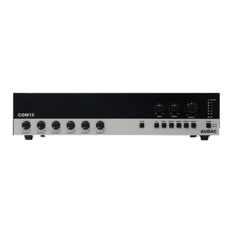
AUDAC COM12 Installation and operating instructions

AUDAC

AUDAC COM12 Installation and operating instructions

AUDAC PRE220 User manual

AUDAC

AUDAC PRE220 User manual

AUDAC Dante AMP203LO User manual

AUDAC

AUDAC Dante AMP203LO User manual

AUDAC CEP Series User manual

AUDAC

AUDAC CEP Series User manual

AUDAC SMQ User manual

AUDAC

AUDAC SMQ User manual

AUDAC AMP523MK2 User manual

AUDAC

AUDAC AMP523MK2 User manual

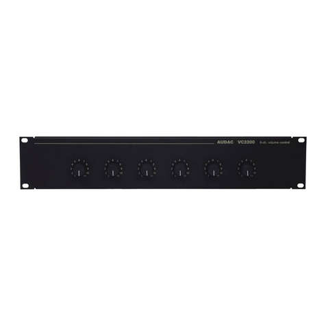
AUDAC vc2200 User manual

AUDAC

AUDAC vc2200 User manual

AUDAC R2 User manual

AUDAC

AUDAC R2 User manual

AUDAC PRE116 User manual

AUDAC

AUDAC PRE116 User manual

AUDAC POW2 User manual

AUDAC

AUDAC POW2 User manual

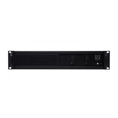
AUDAC D2 User manual

AUDAC

AUDAC D2 User manual

AUDAC DPA74 Installation and operating instructions

AUDAC

AUDAC DPA74 Installation and operating instructions

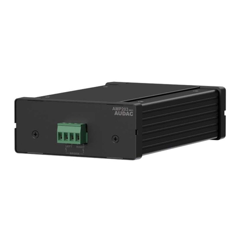
AUDAC AMP203 Installation instructions

AUDAC

AUDAC AMP203 Installation instructions

AUDAC Multi-functional SourceCon MFA208 User manual

AUDAC

AUDAC Multi-functional SourceCon MFA208 User manual

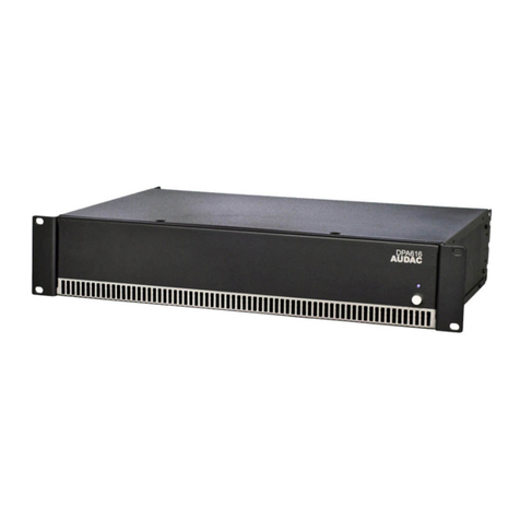
AUDAC DPA616 User manual

AUDAC

AUDAC DPA616 User manual

AUDAC M1 Installation and operating instructions

AUDAC

AUDAC M1 Installation and operating instructions

AUDAC PX110 User manual

AUDAC

AUDAC PX110 User manual

AUDAC COM12 Mk2 User manual

AUDAC

AUDAC COM12 Mk2 User manual

AUDAC CAP224 User manual

AUDAC

AUDAC CAP224 User manual

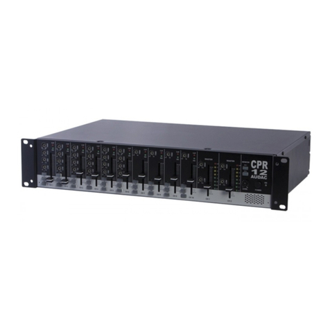
AUDAC CPR12 Installation and operating instructions

AUDAC

AUDAC CPR12 Installation and operating instructions

Popular Amplifier manuals by other brands

Magnat Audio EDITION FOUR Owner's manual/warranty document

Magnat Audio

Magnat Audio EDITION FOUR Owner's manual/warranty document

Inter-m PA-2000A Operation manual

Inter-m

Inter-m PA-2000A Operation manual

Yamaha TX6n owner's manual

Yamaha

Yamaha TX6n owner's manual

Peavey TNT 150 user guide

Peavey

Peavey TNT 150 user guide

Bosch LBB 1903/10 Installation and user instructions

Bosch

Bosch LBB 1903/10 Installation and user instructions

Avocent Emerge DA1200D Installer/user guide

Avocent

Avocent Emerge DA1200D Installer/user guide

Redgum RGi35 operating instructions

Redgum

Redgum RGi35 operating instructions

Cambridge Audio AXA25 user manual

Cambridge Audio

Cambridge Audio AXA25 user manual

Alpine MRP-M200 owner's manual

Alpine

Alpine MRP-M200 owner's manual

Technical Pro H1502UrBT user manual

Technical Pro

Technical Pro H1502UrBT user manual

FMS EMGZ307 operating manual

FMS

FMS EMGZ307 operating manual

Racal Instruments 5601 user manual

Racal Instruments

Racal Instruments 5601 user manual

Valcom V-1094A Technical specifications

Valcom

Valcom V-1094A Technical specifications

Cambridge Audio 851D user manual

Cambridge Audio

Cambridge Audio 851D user manual

QSC 3800 Specifications

QSC

QSC 3800 Specifications

NAD C300 owner's manual

NAD

NAD C300 owner's manual

Rotel RMB-1077 owner's manual

Rotel

Rotel RMB-1077 owner's manual

Peavey Monitor 300 Series operating guide

Peavey

Peavey Monitor 300 Series operating guide

manuals.online logo
manuals.online logoBrands
  • About & Mission
  • Contact us
  • Privacy Policy
  • Terms and Conditions

Copyright 2025 Manuals.Online. All Rights Reserved.

PROFESSIONAL AUDIO EQUIPMENT
Multi-room Amplifier R1
User Manual
Installation Guide
Multi
-
room
Amp R1
AUDAC
A U D A C P R O F E S S I O N A L A U D I O E Q U I P M E N T
User Manual & Installation Guide
 AUDAC
http://www.audac.be
info@audac.be
2
22
2
INTRODUCTION.....................................................................................................................................................................................................................4
ENVIRONMENT......................................................................................................................................................................................................................5
SAFETY REQUIREMENTS...................................................................................................................................................................................................6
CAUTION
-
SERVICING ......................................................................................................................................................................................................6
PIN CONNECTIONS ON CONNECTORS...........................................................................................................................................................................7
ATTENTION ..........................................................................................................................................................................................................................7
OVERVIEW FRONT AND REAR PANEL OF THE R1....................................................................................................................................................8
FRONT:...................................................................................................................................................................................................................................8
REAR: .....................................................................................................................................................................................................................................8
OVERVIEW ZONE CONTROL ............................................................................................................................................................................................9
ZONE
1
-
8
(FRONT)..............................................................................................................................................................................................................9
OVERVIEW AUDIO INPUTS AND OUTPUTS 1 - 8..........................................................................................................................................................9
INPUT
1-8
(
REAR
)...............................................................................................................................................................................................................9
OVERVIEW PRIORITY INPUTS .......................................................................................................................................................................................10
PRIORITY
INPUT
1
AND
2
(REAR)....................................................................................................................................................................................10
OVERVIEW CASCADED CONTROL PORTS AND AUDIOLINK ..............................................................................................................................10
CASCADING
PORTS
(REAR)............................................................................................................................................................................................10
OVERVIEW DATA CONTROL PORTS............................................................................................................................................................................11
DATA
CONTROL
PART
(REAR).......................................................................................................................................................................................11
GETTING STARTED ............................................................................................................................................................................................................12
SPECIAL FUNCTIONS.........................................................................................................................................................................................................13
S
AVE SETTINGS
......................................................................................................................................................................................................................13
R
ECALL SETTINGS
..................................................................................................................................................................................................................13
E
NABLE OR DISABLE THE ROUTING BUTTONS
.......................................................................................................................................................................13
R
ESET TO FACTORY SETTINGS
...............................................................................................................................................................................................13
WIRE UP THE SYSTEM ......................................................................................................................................................................................................14
REMOTE CONTROL INTERFACE...................................................................................................................................................................................16
STANDARD WEB BASED USER INTERFACE...............................................................................................................................................................17
CONTROL
SCREEN:...........................................................................................................................................................................................................17
CONFIGURATION
SCREEN:.............................................................................................................................................................................................18
CHANGE
PASSWORD
SETTINGS....................................................................................................................................................................................19
CHANGE
NETWORK
SETTINGS .....................................................................................................................................................................................20
CHANGE
PRIORITY
SETTINGS.......................................................................................................................................................................................21
RESTORE
FACTORY
SETTINGS......................................................................................................................................................................................21
TIMER
SETTINGS...............................................................................................................................................................................................................22
TIME
SETTINGS .................................................................................................................................................................................................................23
LITE WEB BASED USER INTERFACE............................................................................................................................................................................24
PURPOSE: ............................................................................................................................................................................................................................24
ACCESS:...............................................................................................................................................................................................................................24
START-UP
SCREEN: ..........................................................................................................................................................................................................24
ROOM
CONFIGURATION
SCREEN:................................................................................................................................................................................25
NAME
CONFIGURATION
SCREEN:................................................................................................................................................................................26
CASCADING THE R1 ...........................................................................................................................................................................................................27
Index
3
33
3
USING THE AUDIO LINK...................................................................................................................................................................................................28
WALL MOUNTED CONTROL PANELS (OPTIONAL).................................................................................................................................................29
JUMPER SETTINGS FOR ZONE OUTPUT SELECTION.............................................................................................................................................30
CONNECTING THE AUDAC PAGING SYSTEM ...........................................................................................................................................................31
ADDITIONAL INFORMATION R1....................................................................................................................................................................................33
T
ECHNICAL SPECIFICATIONS
.................................................................................................................................................................................................33
PERSONAL NOTES...............................................................................................................................................................................................................34
4
44
4
Introduction
This section describes briefly the possibilities of the R1 multi-room amplifier.
he R1 multi-room amplifier is developed as an easy to use, flexible solution for multi-
room use.
During the development of the R1, the AUDAC-engineers wanted to achieve four goals:
-Delivering a flexible audio solution to control multiple zones.
-Easy to use
-Excellent sound quality
-An advanced digital control interface
Where other multi-room amplifiers aren’t ‘all in one’ devices, the R1 is a truly polyvalent solution.
It has the flexibility of an advanced multi-room amplifier, combined with several digital options.
By simply surfing to the webpage, you can get full control of the R1 basic functions. The R1 can
be directly plugged into a basic Ethernet LAN network. No extra control software is needed, just a
computer (pda, pocket pc, …) and a web browser with the Macromedia Flash Player 8.0 (or
higher) plug-in installed, will do the job.
The R1 has 8 stereo line level Inputs, 8 stereo line level outputs and 8 x 40W stereo amplified
outputs, 2 priority inputs, an audio link input and output. To control al these features, a RS232
port, Ethernet port, 8 RS485 ports to connect wall mounted control panels and a data uplink and
downlink are present.
The R1 can be used in commercial applications such as restaurants, clubs, bars, theatres, hotels,
conference facilities, houses of worship, professional offices, public buildings, private houses…
As a simple example, when installed in a private house, you could connect: a tuner to play your
favorite radio-station in the kitchen, a CD-player to play relaxing music in the bathroom, a PC to
play your MP3 songs, your TV to boost-up the surround sound while looking at your favorite
movie, … and on top of it, you could also connect your doorbell to one of the priority input
channels so you hear when someone is ringing at your door.
Each zone can have one or more digital wall mounted control panels for selecting a music source,
and setting the volume. Up to 8 wall mounted control panels are possible.
It is also possible to connect the Audac Paging System to the R1 using the APM-Amplifier
interface.
T
5
55
5
nvironment
Do not place this unit in an enclosed envi onment such as a bookshelf o closet. Ensu e
the e is adequate ventilation to cool the unit. Do not block the ventilation openings.
Do not place the unit in envi onments which contain high levels of dust, heat, moistu e o
vib ation.
Do not use the unit nea wate o othe liquids. Make su e no wate o othe liquids can be
spilled, d ipped o splashed on the unit.
The unit is developed fo indoo use only. Do not use the unit outdoo s.
Do not place objects (books, vases, …) on top of the unit.
Place the unit on a stable base.
Chapter
1
6
66
6
Safety Requirements
Always handle the unit with ca e.
Only use a g ounded socket outlet and a powe co d with g ounding plug to plug in the
unit.
This unit is not a toy. It should not be ope ated by child en.
Do not stick objects th ough the ventilation openings of the R1.
Do not open the unit. ( isk fo elect ical shock)
The R1 contains seve al ‘jumpe s’ which can be set. These settings may only be done by
qualified people.
CAUTION - S RVICING
This unit contains no user serviceable parts. Refer all
servicing to qualified service personnel. Do not perform
any servicing unless you are qualified to do so.
Note
This product conforms to the following European Standards: EN 50081-1: 1992, EN
50082-1: 1992, EN 60065: 1994



7
77
7
Pin connections on Connectors
Cinch (RCA): tip = Signal (left or right), Ring = Ground
RJ45 (RS485) Wall panel , Datalink:
RS232 (se ial connection inte face)
The serial data protocol and wiring for the R1 can be downloaded at www.audac.be/download or
can be asked at info@audac.be.
ATT NTION
The Cat5 cabling must always be ‘straight’. In case of self made
cabling, it must be done as described above, to make the system
work properly.
Pin 1 White-Orange
/
Pin 2 Orange /
Pin 3 White-Green +12V DC
Pin 4 Blue RS485 A
Pin 5 White-Blue RS485 B
Pin 6 Green GND
Pin 7 White-Brown /
Pin 8 Brown /



8
88
8
Overview front and rear panel of the R1
FRONT:
R AR:
Chapter
2
9
99
9
Overview Zone Control
ZON 1 - 8 (FRONT)
Overview Audio Inputs and Outputs 1 - 8
INPUT 1-8 ( R AR )
Routing Button
Input Clipping LED
Input Gain Control
Stereo Line Input
(Cinch, line level)
Stereo Zone Output
(Cinch, line level)
Amplified Zone Outputs
8 x 40W stereo
Routing Leds
Status Leds
Power Button
Zone Output 2 Band Tone Control
Zone Output Level VU
-
Bar
Zone Output Volume Control