manuals.online logo
Brands
  1. Home
  2. •
  3. Brands
  4. •
  5. AUDAC
  6. •
  7. Speakers
  8. •
  9. AUDAC CALI Series User manual

AUDAC CALI Series User manual

This manual suits for next models

3

Other AUDAC Speakers manuals

AUDAC LINO4 Guide

AUDAC

AUDAC LINO4 Guide

AUDAC ATEO M Series User manual

AUDAC

AUDAC ATEO M Series User manual

AUDAC WXMK2 Series Guide

AUDAC

AUDAC WXMK2 Series Guide

AUDAC MERO5 Guide

AUDAC

AUDAC MERO5 Guide

AUDAC ALTI Series Guide

AUDAC

AUDAC ALTI Series Guide

AUDAC WMM630 User manual

AUDAC

AUDAC WMM630 User manual

AUDAC Ateo 2 Guide

AUDAC

AUDAC Ateo 2 Guide

AUDAC NELO706V Series User manual

AUDAC

AUDAC NELO706V Series User manual

AUDAC AWP06 Installation and operating instructions

AUDAC

AUDAC AWP06 Installation and operating instructions

AUDAC WX502 Installation and operating instructions

AUDAC

AUDAC WX502 Installation and operating instructions

AUDAC KYRA24 Guide

AUDAC

AUDAC KYRA24 Guide

AUDAC WS500 User manual

AUDAC

AUDAC WS500 User manual

AUDAC VEXO110 User manual

AUDAC

AUDAC VEXO110 User manual

AUDAC GIAX Installation and operating instructions

AUDAC

AUDAC GIAX Installation and operating instructions

AUDAC NELO706 Series User manual

AUDAC

AUDAC NELO706 Series User manual

AUDAC CSE55 Installation and operating instructions

AUDAC

AUDAC CSE55 Installation and operating instructions

AUDAC WX802/OB Installation and operating instructions

AUDAC

AUDAC WX802/OB Installation and operating instructions

AUDAC WXMK2 Series Guide

AUDAC

AUDAC WXMK2 Series Guide

AUDAC VEXO 8 Guide

AUDAC

AUDAC VEXO 8 Guide

AUDAC SPRING-FIT CENA506 User manual

AUDAC

AUDAC SPRING-FIT CENA506 User manual

AUDAC AXIR Installation and operating instructions

AUDAC

AUDAC AXIR Installation and operating instructions

AUDAC Ateo 4 Guide

AUDAC

AUDAC Ateo 4 Guide

AUDAC WX802/W Installation and operating instructions

AUDAC

AUDAC WX802/W Installation and operating instructions

AUDAC ATEO2D Guide

AUDAC

AUDAC ATEO2D Guide

Popular Speakers manuals by other brands

Electro-Voice LR4S engineering data

Electro-Voice

Electro-Voice LR4S engineering data

Definitive Technology Sound Cylinder user guide

Definitive Technology

Definitive Technology Sound Cylinder user guide

AudioSource LS545 user manual

AudioSource

AudioSource LS545 user manual

Paso C402-T Instructions for use

Paso

Paso C402-T Instructions for use

Altec Lansing 416-8C LF SPEAKER manual

Altec Lansing

Altec Lansing 416-8C LF SPEAKER manual

Kenwood KFC-1072 Servise manual

Kenwood

Kenwood KFC-1072 Servise manual

Peavey ProSys 112 user guide

Peavey

Peavey ProSys 112 user guide

JBL Control Contractor 60 Series installation instructions

JBL

JBL Control Contractor 60 Series installation instructions

Aura STORM-8 owner's manual

Aura

Aura STORM-8 owner's manual

Oontz ANGLE 3 PLUS quick start guide

Oontz

Oontz ANGLE 3 PLUS quick start guide

Electro-Voice LR4A engineering data

Electro-Voice

Electro-Voice LR4A engineering data

Rave RK-650-ICA-B owner's manual

Rave

Rave RK-650-ICA-B owner's manual

Flux Reference Series installation manual

Flux

Flux Reference Series installation manual

Lanzar AQAWBS64BK installation manual

Lanzar

Lanzar AQAWBS64BK installation manual

DAPAudio DCS-6230 manual

DAPAudio

DAPAudio DCS-6230 manual

Aluratek ABS03F quick start guide

Aluratek

Aluratek ABS03F quick start guide

Kenwood KES-5A instruction manual

Kenwood

Kenwood KES-5A instruction manual

Sonance ORIGINAL SERIES instruction manual

Sonance

Sonance ORIGINAL SERIES instruction manual

manuals.online logo
manuals.online logoBrands
  • About & Mission
  • Contact us
  • Privacy Policy
  • Terms and Conditions

Copyright 2025 Manuals.Online. All Rights Reserved.

INSTALLATION MANUAL
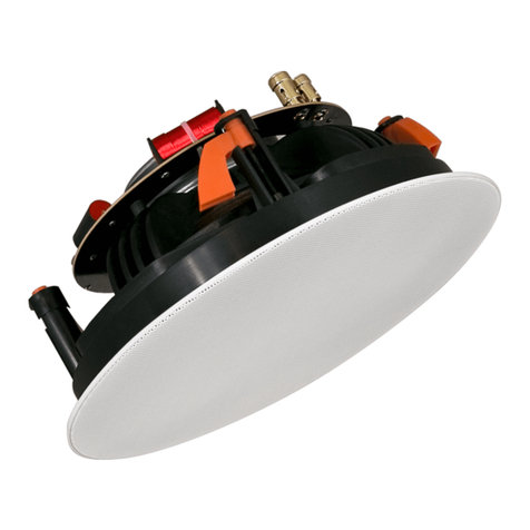
CALI SERIES SAFE-LATCH™ CEILING SPEAKERS WITH REAR-DOME
STEP 1 STEP 2
Cut a hole on the mounting location in the ceiling.
Make sure the diameter is matching the cut-out
measurement for the loudspeaker.
Double check if there are no cables or other
obstructions behind the mounting surface before
making the cut-out.
Remove the cover and connect the cables to the
ceramic connection terminal by inserting the cable in
the corresponding hole and tightening the screw. The
remaining two terminals can be used to link through
to other speakers.
Reattach the cover plate and tighten the cable strain
relief.
Ø Diameter
STEP 3 STEP 4
Make sure the spacing between the mouting surface
and the clamp is bigger than the thickness of your
ceiling plate. Insert the speaker until the clamps snap
in place
Fix the speaker in the provided opening by tightening
the screws of the mounting clamps using a screw
driver.
An optional tile bridge must be installed when
mounting the speaker in ceiling tiles.
STEP 5 STEP 6
Using a at head screwdriver, the power tap or low
impedance selection can be made.
Attach the grill to the speaker by inserting the lips into
the provided openings on the speaker bae and rotate
it over a partial turn (15°).
The speaker is now correctly installed and ready for
use.
The WEEE marking indicates that this product
should not be disposed with regular household
waste at the end of its product life. This regulation
is created to protect both the environment and
human health.
This product is developed and manufactured with
high quality materials and components which can
be recycled and/or reused. Please dispose of this
product at your local collection point or recycling
center for electrical and electronic waste. Do this
to make sure that the product is recycled in an
environmental friendly way, and help to protect
the environment in which we all live.
INSTALLATION MANUAL
CALI SERIES SAFE-LATCH™ CEILING SPEAKERS WITH REAR-DOME
•
IF THERE IS ANY DAMAGE TO THE CARTON BOX
OR THE UNIT ITSELF, INFORM YOUR VENDOR
IMMEDIATELY.
•
ALWAYS FOLLOW THE LOCAL REGULATIONS AND
REQUIREMENTS REGARDING INSTALLATION,
SUSPENSION AND CONNECTION OF THIS
LOUDSPEAKER. EVEN WHEN OTHERWISE SPECIFIED
IN THIS DOCUMENT.
• THE INSTALLATION OF THIS LOUDSPEAKER SHALL
BE DONE BY QUALIFIED PERSONNEL ONLY.
•
USE CABLES OF THE RIGHT GAUGE TO CONNECT
THE LOUDSPEAKER
•
USE CABLES WITH CLEAR COLOR CODING
INDICATING THE POLARITY AND MAINTAIN THE
SAME POLARITY THROUGHOUT THE WHOLE
SYSTEM.
•
ONLY USE THE CORRECT AMPLIFIER OUTPUT
VOLTAGE AND IMPEDANCE. EXCEEDING THESE
LIMITS COULD CAUSE FIRE OR OTHER FAILURES.
•
AVOID EXPLOSIONS: DO NOT USE THE SPEAKER
AROUND GASOLINE, THINNER OR OTHER
COMBUSTIBLES
•
AVOID ELECTRIC SHOCKS: SWITCH OFF THE
AMPLIFIER WHEN CONNECTING THE LOUDSPEAKER
•
DO NOT USE THE LOUDSPEAKER FOR AN EXTENDED
PERIOD OF TIME AT DISTORTED SOUND. THIS
COULD CAUSE PERMANENT DAMAGE.
•
ALWAYS KEEP THESE INSTRUCTIONS FOR FUTURE
REFERENCE. NEVER THROW THEM AWAY
• ALWAYS HANDLE THIS UNIT WITH CARE
• CLEAN ONLY WITH DRY CLOTH
•
HEED ALL WARNINGS AND FOLLOW ALL
INSTRUCTIONS
•
NEVER EXPOSE THIS EQUIPMENT TO RAIN,
MOISTURE, ANY DRIPPING OR SPLASHING LIQUID.
•
DO NOT INSTALL THIS UNIT NEAR ANY HEAT
SOURCES SUCH AS RADIATORS OR OTHER
APPARATUS THAT PRODUCE HEAT
•
DO NOT PLACE THIS UNIT IN ENVIRONMENTS
WITH A HIGH LEVEL OF DUST, HEAT, MOISTURE OR
VIBR ATION
• THIS UNIT IS DEVELOPED FOR INDOOR USE ONLY.
DO NOT USE IT OUTDOORS
•
ONLY USE ATTACHMENTS & ACCESSORIES SPECIFIED
BY THE MANUFACTURER.
•
ONLY INSTALL THE SPEAKER IN LOCATIONS THAT
CAN STRUCTURALLY SUPPORT THE WEIGHT OF THE
SPEAKER. IGNORING THIS CAN BRING THE SPEAKER
DOWN.
•
DO NOT USE ANY OTHER METHOD THAN SPECIFIED
TO MOUNT THE SPEAKER. IF EXTREME FORCE IS
APPLIED TO THE SPEAKER, IT COULD FALL DOWN
•
ATTACH A SAFETY WIRE TO THE SPEAKER WHEN
IT IS MOUNTED HIGH UP. ONLY USE INDUSTRY-
ACCEPTED RIGGING TOOLS AND METHODS
• CAREFULLY CHECK THE UNIT’S CONDITION AFTER
UNPACKING.
PRECAUTIONS
This product contains no user serviceable parts.
Refer all servicing to qualied service personnel. Do
not perform any servicing (unless you are qualied
to do so.)
CAUTION - SERVICING
This product conforms to all the essential
requirements and further relevant specications
described in following directives: 2014/30/EU (EMC)
and 2014/35/EU (LVD)
EC DECLARATION OF CONFORMITY
WASTE OF ELECTRICAL AND ELECTRONIC
EQUIPMENT (WEEE)
Model Max. Power RMS Power Cut-out
dimension
Dimensions Line transformer power
tappings - Impedance
CALI424
CALI660
60 Watt
120 Watt
30 Watt
60 Watt
Ø 170 mm
Ø 220 mm
Ø 192 x 114 mm
Ø 242 x 124 mm
24W / 12W / 6W - 8 Ω
60W / 30W / 15W - 8 Ω