Audi A5 SPORTBACK Manual

393
All rights reserved. Technical
specifications subject to change
without notice.
Copyright
AUDI AG
I/VK-35
Service.training@audi.de
Fax +49-841/89-36367
AUDI AG
D-85045 Ingolstadt
Technical status: 01/07
Printed in Germany
A07.5S00.35.20
Audi A5 -
Convenience Electronics and Driver Assist Systems
Self-Study Programme 393
Vorsprung durch Technik www.audi.de Service Training

The new Audi A5
The new Audi A5 features a number of impressive
innovations in the area of convenience electronics.
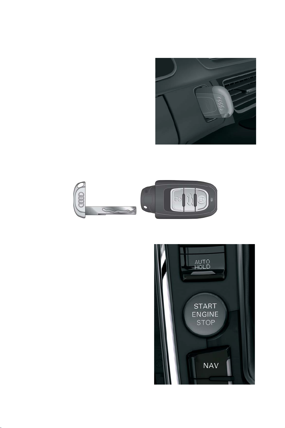
One of the most striking of these is the new ignition
key. This key is pushed into the electronic ignition
lock, and the engine is started with a push move-
ment of the key instead of a turning movement.This
new concept replaces the button-operated folding
key.
The ignition key houses an emergency key which
allows the vehicle to be opened mechanically in
case of failure of the vehicle electronics. The igni-
tion key can also be used to lock the vehicle
mechanically if the key removal lock prevents with-
drawal of the key from the ignition lock.
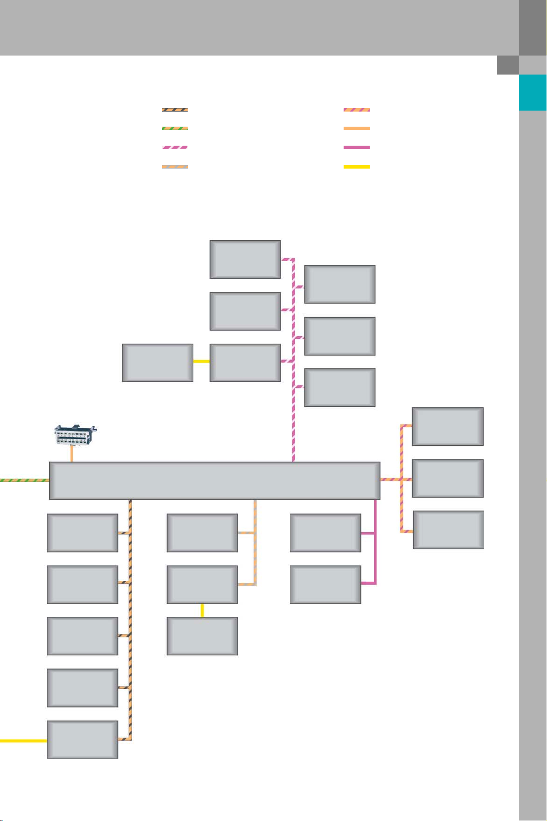
The new Audi A5 comes with an extensive range of
optional equipment. Many systems previously
exclusive to the larger models A6, Q7 and A8 are
now also available on the A5.
Systems include the "Advanced Key" and the front
and rear acoustic parking system, which is available
with an auxiliary visual display under the name
"Audi Parking System Plus". The acoustic parking
system can also be ordered in combination with a
rear-view camera under the name "Audi Parking Sys-
tem Advanced", this being the full-expanded version
of the acoustic parking system.
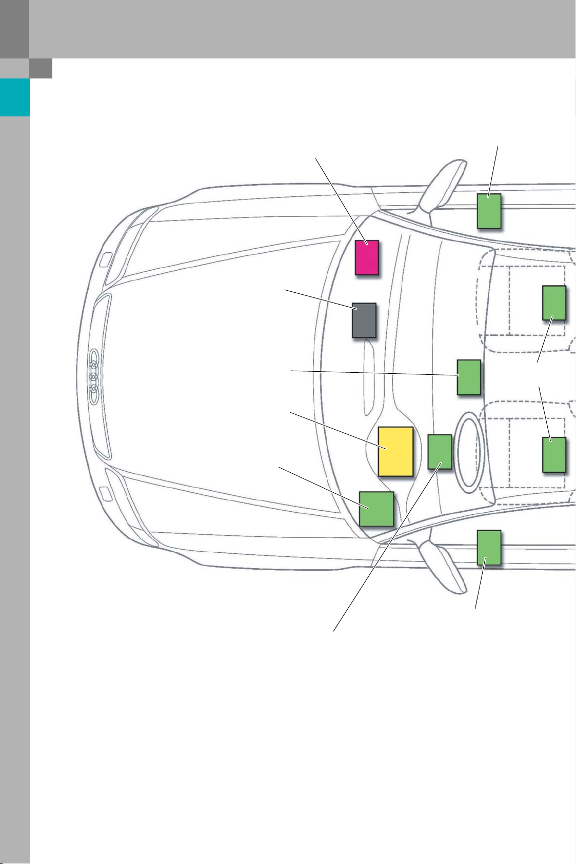
The wide range of optional equipment on the Audi
A5 also includes a lane change assistant system
which assists the driver when changing lane by
means of an indicator light in the exterior mirrors.
However, the absolute highlight on the new Audi A5
is the Audi Lane Assist system, which will be availa-
ble for order in 2007. In June 2007, there will be a
separate self-study programme about this system,
which explains why the system is not described in
this self-study programme.
393_034
393_042
393_046

NoteReference
The self-study programme teaches the design and function of new vehicle models,
new automotive parts or new technologies.
The self-study programme is not a repair manual!
All values given are intended as a guideline only and refer to the software version valid at the time of
preparation of the SSP.
For maintenance and repair work, always refer to the current technical literature.
Contents
Control unit with display in dash panel insert . . . . . . . 10
Door control units . . . . . . . . . . . . . . . . . . . . . . . . . . . . . . . 14
Seat control units . . . . . . . . . . . . . . . . . . . . . . . . . . . . . . . . 16
Convenience system central control unit . . . . . . . . . . . 21
Networking / vehicles with infotainment CAN bus . . . . . . . . . . . . . . . . . . . . . . . . . 4
Networking / vehicles with MOST bus. . . . . . . . . . . . . . . . . . . . . . . . . . . . . . . . . . . . 6
Installation locations of the control units . . . . . . . . . . . . . . . . . . . . . . . . . . . . . . . . . 8
Overview . . . . . . . . . . . . . . . . . . . . . . . . . . . . . . . . . . . . . . . . 4
Personalisation and adaption channels . . . . . . . . . . . . . . . . . . . . . . . . . . . . . . . . . 24
The electronic ignition lock . . . . . . . . . . . . . . . . . . . . . . . . . . . . . . . . . . . . . . . . . . . . 26
The ignition key . . . . . . . . . . . . . . . . . . . . . . . . . . . . . . . . . . . . . . . . . . . . . . . . . . . . . . 27
The electrical steering column lock . . . . . . . . . . . . . . . . . . . . . . . . . . . . . . . . . . . . . 31
Advanced Key . . . . . . . . . . . . . . . . . . . . . . . . . . . . . . . . . . . . . . . . . . . . . . . . . . . . . . . . 34
The "Audi Service Key". . . . . . . . . . . . . . . . . . . . . . . . . . . . . . . . . . . . . . . . . . . . . . . . . 38
Immobiliser V . . . . . . . . . . . . . . . . . . . . . . . . . . . . . . . . . . . . . . . . . . . . . . . . . . . . . . . . 42
The anti-theft alarm system . . . . . . . . . . . . . . . . . . . . . . . . . . . . . . . . . . . . . . . . . . . . 44
The HomeLink garage door opener . . . . . . . . . . . . . . . . . . . . . . . . . . . . . . . . . . . . . 45
The Panorama tilt sunroof . . . . . . . . . . . . . . . . . . . . . . . . . . . . . . . . . . . . . . . . . . . . . 46
Park assist control unit (acoustic parking system). . . . 48
Rear-view camera system control unit. . . . . . . . . . . . . . 51
Lane change assistant control unit . . . . . . . . . . . . . . . . 52

4
Networking / vehicles with infotainment CAN bus
Overview
Air quality sensor
G238
Refrigerant pres-
sure/temperature
sender G395
Garage door opera-
tion control unit
J530
Light switch
E1
Wiper motor con-
trol unit
J400
Rain and light
detector sensor
G397
Electrical steering
column lock con-
trol unit
J764
Entry and start
authorisation
switch E415
Garage door operat-
ing unit
E284
Sliding sunroof con-
trol unit
J245
Anti-theft alarm
system sensor
G578
Humidity sender
G355
Onboard power supply
control unit
J519
Convenience system central
control unit
J393
Alarm horn
H12
Climatronic control unit
J255
Fresh air blower
control unit J126
Control motors for
flap control
Trailer detector
control unit
J345
Steering column
electronics con-
trol unit
J527
Rear-view camera
system
J772
Multi-function
steering wheel
control unit
J453
Seat and steering
column adjustment
control unit with
memory function
J136
Seat adjustment
control unit with
memory, front pas-
senger J521
Driver door con-
trol unit
J386
Front passenger
door control unit
J387
Power output
module for left
headlight
J667
Power output
module for right
headlight
J668

5
Diagnostic port
Control unit with
display in dash
panel insert J285
Yaw rate sender
G202
Park assist
control unit
J791
ABS control unit
J104
Steering angle
sender G85
Electric park
and handbrake
control unit
J540
Additional heater
control unit J364
Radio
R
Digital sound
package control
unit J525
Tele p h one t ra n s -
mitter and
receiver unit
R36
Data bus diagnostic interface J533
Battery monitor
control unit
J367
3-phase AC
alternator
C
Adaptive cruise
control unit
J428
Lane change
assistant control
unit
J769
Lane change
assistant control
unit -2-
J769
Airbag control
unit J234
Engine control
unit J623
Automatic gear-
box control unit
J217
ECD control unit
(electronically
controlled damp-
ing) J250
Headlight range
control, control unit
J431
393_050
Powertrain CAN bus
Convenience CAN bus
Dash panel insert/suspension CAN bus
CAN-Extended
Infotainment CAN bus
Diagnostics CAN bus
LIN bus
Subbus systems

6
Overview
Air quality sensor
G238
Refrigerant pres-
sure/temperature
sender
G395
Garage door opera-
tion control unit
J530
Light switch
E1
Wiper motor con-
trol unit
J400
Rain and light
detector sensor
G397
Electrical steering
column lock
control unit
J764
Entry and start
authorisation
switch
E415
Garage door oper-
ating unit
E284
Sliding sunroof
control unit
J245
Anti-theft alarm
system sensor
G578
Humidity sender
G355
Onboard power supply
control unit
J519
Convenience system central
control unit
J393
Alarm horn
H12
Climatronic control unit
J255
Fresh air blower
control unit J126
Control motors for
flap control
Tra ile r det e ctor
control unit
J345
Steering column
electronics con-
trol unit
J527
Rear-view camera
system
J772
Multi-function
steering wheel
control unit
J453
Seat and steering
column adjustment
control unit with
memory function
J136
Seat adjustment
control unit with
memory, front
passenger J521
Driver door con-
trol unit
J386
Front passenger
door control unit
J387
Power output
module for left
headlight
J667
Power output
module for right
headlight
J668
Airbag control
unit J234
Engine control
unit J623
Automatic gear-
box control unit
J217
ECD control unit
(electronically
controlled damp-
ing) J250
Headlight range
control, control
unit
J431
Networking / vehicles with MOST bus

7
Front information
control unit
J523
Telephone trans-
mitter and
receiver unit
R36
Operating electron-
ics control unit, nav-
igation
J401
TV tuner
R78
CD changer
R41
Connection
for external
audio sources
R199
Digital radio
R147
Digital sound
package control
unit
J525
Voice input con-
trol unit J507
Radio
R
Data bus diagnostic interface J533
Battery monitor
control unit
J367
3-phase AC
alternator
C
Adaptive cruise
control unit
J428
Lane change
assistant control
unit
J769
Lane change
assistant control
unit -2-
J769
Diagnostic port
Control unit with
display in dash
panel insert J285
Yaw ra te sende r
G202
Park assist control
unit J791
ABS control unit
J104
Steering angle
sender G85
Electric park and
handbrake control
unit
J540
Additional heater
control unit
J364
393_051
Powertrain CAN bus
Convenience CAN bus
Dash panel insert/suspension CAN bus
CAN Extended
Diagnostics CAN bus
LIN bus
Subbus systems
Most bus

8
Overview
Installation locations of the control units
Headlight range control,
control unit
Door control unit
Data bus
diagnostic interface
Climatronic
control unit
Dash panel insert
control unit
Onboard power supply control unit
Seat memory
control units
Door control unit
Steering column electronics
control unit

9
393_049
Dash panel insert/suspension CAN bus users
Convenience CAN bus users
Powertrain CAN bus users
CAN-Extended users
Lane change assist control
unit (slave)
Convenience system
central control unit
Acoustic parking system
control unit
Trailer detector
control unit
Rear-view camera
system control unit
Lane change assist
control unit (master)

10
Control unit with display in dash panel insert
393_001
New features
The dash panel insert of the new Audi A5 explores new directions with its styling and concept. It is very differ-
ent to the dash panel inserts in other Audi models in several respects. The most obvious changes are:
• The zero position of the rev counter and speedometer is the so-called "6 o'clock position". The top end of
the scale is the "3 o'clock position".
• After "ignition "on"", the dial makes a full scale sweep.
• Neither of the small displays in the rev counter and the speedometer is required. The trip mileage and total
mileage, as well as the date and time, are indicated on the centre display
• The upshift indicator in the centre display help the driver to maintain a fuel-efficient driving style
(detailed information is given in a separate chapter)
• The fuel tank sender and the radio digital clock module are the only vehicle components which are still
hard-wired to the control unit with display in dash panel insert J285
• The new master for display lighting terminal 58d is the onboard power supply control unit J519, and no
longer the dash panel insert
Control unit with display in dash panel insert

11
Versions of the dash panel insert
Depending on vehicle type and the country in which
the vehicle is registered, the following differences
exist between the individual dash panel inserts:
– Petrol engine / diesel engine
– Distance to destination display in kilometres,
miles (UK) or miles (USA)
– Analog display of coolant temperature in ºC or ºF
– Midline dash panel insert (DOT matrix) or High-
line dash panel insert (colour TFT display)
– Highline dash panel insert with or without speed-
ometer ring display for ACC
Information shown on the centre display of the
dash panel insert
The user can scroll through the individual display
levels in the dash panel insert by pressing Reset
button on the onboard computer in the windscreen
wiper stalk. The displays in an Audi A5 are shown
below with the optional dash panel insert with col-
our display and navigation system.
393_002

12
Control unit with display in dash panel insert
The upshift indicator
Function
The upshift indicator in the driver information sys-
tem is a new function designed to help the driver to
reduce fuel consumption. The function is integrated
in the engine management software. It is featured
on all petrol and diesel models with manual gear-
box.
As modern vehicle engines deliver high torque even
at low rpm, it is often possible to drive in a higher
gear.In this case, a gearshift recommendation is
indicated to the driver via the driver information sys-
tem. The gearshift recommendation may involve
skipping a gear.
The actual gear position is indicated continuously in
the driver information system. This information is
derived from the actual engine speed and road
speed signals. Neither the actual gear position nor
any gearshift recommendations are indicated while
the clutch is actuated (for longer than 2 seconds).
No gearshift recommendation is given when the
engine is operating at full throttle either.
Normally no gearshift recommendation is issued
when the vehicle is in overrun. However, if the
engine speed drops below a critical threshold, a rec-
ommendation to shift down a gear will be given.
To implement the "upshift indicator" function, the
engine control unit also requires information from
the steering angle sender G85, the ABS control unit
J104 and the convenience system control unit J393.
The engine control unit receives this information via
CAN bus.
393_043
Upshift indicator in Midline or Highline dash panel insert
Indicator
The gearshift recommendation computed by the engine control unit is transmitted via CAN bus to the dash
panel insert and displayed in the driver information system. There are two possible states of the display:
1 The actual gear position is displayed with or without a gearshift recommendation.
2 No display. This is the case if the clutch is actuated for longer than two seconds or if the driver has deac-
tivated the function on the MMI.

13
Electrical connections of the control unit with display in dash panel insert
Lines on the dash panel insert of the Audi A4 ’05 Solution in the new Audi A5
Line to brake pad monitoring system is read in by onboard power supply control unit J519
Line to brake fluid switch is read in by onboard power supply control unit J519
Line to oil pressure switch is read in either by the engine control unit or by the
onboard power supply control unit J519, depending
on engine type
2 lines to the transmitter and receiver coil in the igni-
tion switch
The key recognition components are now integrated
in the electronic ignition lock or in the convenience
system control unit J393
Line to front-end ambient temperature sensor is read in by onboard power supply control unit J519
Line to coolant temperature sensor is read in by onboard power supply control unit J519
Line to coolant level switch is read in by onboard power supply control unit J519
Line to washer fluid level switch is read in by onboard power supply control unit J519
Line to bonnet switch is read in by onboard power supply control unit J519
Line to oil level and oil temperature sensor is read in by the engine control unit
K wire The K wire is no longer needed!
Terminal 58s is output by the onboard power supply control unit
J519
Terminal 58d is output by the onboard power supply control unit
J519
Terminal 61 / alternator charge indicator lamp is a LIN bus user at the data bus diagnostic interface
J533 (LIN master)
Term i n a l 1 5 is no longer needed as a discrete input at J285
Radio controlled clock earth wire The radio controlled clock uses an external earth
Terminal 31 for sensors is provided by onboard power supply control unit
J519
5 lines to the Navigation Low setting switch The setting switch is no longer needed!
The following lines are now connected to other control units:
The following lines are connected to the control unit with display in dash panel insert on the Audi A5:
– 2 lines terminal 30
– 2 lines terminal 31
– A 5V supply line to the radio digital clock module (radio-controlled clock is optional)
– A signal line to the radio digital clock module (radio-controlled clock is optional)
– 2 test leads to fuel tank sender 1
– 2 test leads to fuel tank sender 2 (quattro models only)
– An earth wire to the fuel tank senders
– 2 CAN lines of the dash panel insert/suspension CAN

14
Door control units
Introduction
The door control units in the new Audi A5 are simi-
lar in design to those on the Audi A6 and Audi Q7:
the control unit and the window regulator motor are
two discrete components.
LED side indicators are integrated in the exterior
mirrors of the new A5. They are activated by the
associated door control units.
393_025 393_026
Versions
The two door control units of the new Audi A5 are distinguished as driver and passenger control units (and
not as left or right door control units).
The door control will be are available in the entry-level and full-spec versions. Full-spec door control units sup-
port the following additional functions and components:
• Convenience fold-back door mirrors
• Electrochromatic mirror
• Mirror potentiometer for actual mirror glass position sensing
• Control panel for storing personal settings (mirror glass and seat positions)
Door control units

15
Sensorless position recognition (SLP)
The door control units in the new Audi A5 do not
use Hall sensors for window glass position recogni-
tion. For the first time, the A5 uses the so-called
sensorless position recognition system (SLP), allow-
ing the previously used Hall sensor to be dispensed
with.
The sensorless position recognition system meas-
ures the harmonic content of the electrical current
drawn by the window regulator motor. The speed of
the window regulator motor and the actual window
glass position are determined from this informa-
tion.
393_027
Te r m i na l 3 0
Door control unit,
driver side
J368
Convenience CAN bus
Window
regulator
motor
The harmonic content is due to the continuous reversal in the polarity at the capacitor of the window regula-
tor motor.
The harmonic content measurement and analysis are also used to provide anti-pinch protection. Each revolu-
tion of the motor produces eight harmonics.
Convenience fold-back
The "convenience door mirror fold-back" feature is
optional on the A5. The driver can specify in the CAR
menu on the MMI whether the door mirrors auto-
matically fold back or not after locking the vehicle.
Accordingly, the door mirrors return automatically
to their initial position after "ignition "on"".
Note: A shunt is a very small resistance which is used for the measurement of electrical current.
The voltage drop across the shunt is measured by the control unit. The electrical current is calculated from the
measured voltage.

16
Seat control units
Introduction
Electrically adjustable seats and a seat memory are
available as optional equipment for the new Audi
A5. The seat memory will only be available for the
driver's seat on the Audi A5. It allows various posi-
tions of the driver seat and the two door mirrors to
be stored.
If electrically adjustable seats are ordered, they
automatically have a seat control unit in the driver
and front passenger seats. In other vehicle models,
seat control units are required only in combination
with the optional seat memory.
The electrically adjustable basic and sports seats
have the following 5 adjustment motors:
1 Longitudinal seat adjustment motor
2 Seat height adjustment motor
3 Seat angle adjustment motor
4 Backrest adjustment motor
5 Head restraint adjustment motor
The Super sports seat has fixed head restraints and
therefore has only four adjustment motors.
Seat memory
Stored settings
The following settings are stored by pressing the
Save button on the driver side memory block by
locking the vehicle with the remote control key:
– Actual position of left and right exterior mirrors
– Actual positions of the 5 driver seat adjustment
motors
The driver side control unit J136 can store up to six
different settings. Two settings can be stored with
the Save buttons, and another four with different
remote control keys.
The ON/OFF switch
The basic requirement for all memory operations as
well as convenience functions such as seat symme-
try, comfort side view and seat adjustment with the
easy entry switch is that the ON/OFF switch of the
memory block is at "ON".
The position of this switch is read in by driver door
control unit J386 and transferred the control unit via
the CAN bus. However, the switch position is also
hard wired through the driver door control unit and
from here to the seat control unit ("emergency OFF
line" in the electrical system overview).
If the switch is at "OFF", a hardware device prevents
switching of the power modules for motor activa-
tion, which means that no adjustments can be
made. If the switch is at "ON" and if adjustments are
being made, all adjustments are aborted immedi-
ately when the OFF switch is actuated.
Seat control units
393_048

17
The settings described above can be saved by
pressing the SET button followed by either of the
memory location buttons. The SET function remains
enabled until the red function indicator LED in the
button goes out.
An acoustic signal is given as feedback after a set-
ting is saved successfully. Again, the prerequisite
for this is that the memory block ON/OFF switch is at
"ON".
Saving settings and adjusting the seats using the programming buttons
If the driver door is open and at "terminal 15 OFF",
the mirrors and the driver's seat can be
adjusted to the pre-configured positions by press-
ing either of the Save buttons once. For this pur-
pose, the driver's door must not already have been
open for longer than 10 minutes.
If the driver door is closed and at "terminal 15 ON",
the Save button must be kept pressed down until
the adjustment is complete. The adjustment can be
interrupted by releasing the Save button.
Saved settings can be retrieved as follows:
To save the current mirror and driver seat settings
to a remote control key,
follow this procedure:
– The settings are saved after closing the driver's
door and locking the vehicle with the remote
control key.
For this purpose, however, the seat back must
not be unlocked.
– After unlocking the vehicle with the remote con-
trol key and opening the driver's door, the mirror,
the driver's seat and the steering column are
adjusted to the positions which have been saved
to the remote control key. The front passenger
seat does not have this function.
However, the function described above will only be
executed properly if two basic requirements are
met:
– "Remote Control Key" must be set to "ON" on the
MMI Car Menu under "Systems", "Seat Settings",
"Driver Seat".
– The memory block ON/OFF switch must be at
"ON".
Saving settings and memory adjustment using a remote control key

18
Seat control units
"Easy entry" function
393_032
Mechanical
backrest unlocking
Easy entry button for elec-
trical forward or back-
ward seat adjustment
The "easy entry" function allows the front seats to be moved into a position in which the rear seats are more
easily accessible.
The complete procedure is as follows:
1 The mechanical backrest unlocking is actuated manually.
2 Actuation is detected by a microswitch in the seat control unit. The head restraints are thereupon
retracted electrically.
3 The backrest is folded forwards manually.
4 Press the easy entry button, and an electric motor moves the seat forward to allow more comfortable
entry.
5 Once the person is seated on the rear of the car, the easy entry button is pressed until the seat has moved
back far enough. The seat stops when it is in its starting position.
6 The seat back is folded back into its starting position.
7 The seat control unit recognises when the backrest has reached its starting position and moves the head
restraints back into their original position.
Note: Steps 5 and 6/7 can also be performed in the reverse order.
In the new Audi A5, the positions of the individual
seat adjustment motors are now detected by a sen-
sorless position recognition system (SLP) instead of
Hall sensors. The system is able to determine the
exact distance travelled by the seat from the har-
monic content of the motor current. For a detailed
description, refer to "Door control units".
At roll-out of the new Audi A5, seat positions will be
determined by both SLP and Hall sensors.
For this reason, the Hall sensors are still shown in
the electrical overview. After a transition period,
production of 4 of the 5 Hall sensors will be discon-
tinued. The Hall sensor in the head restraint adjust-
ment mechanism will continue to be used. The
control unit coding defines which system is cur-
rently in use. In this way, the transition can be made
easily at any time.
Sensorless position recognition system (SLP)

19
Reading in the memory control panel
393_030
Memory operating unit, driver seat
E97
Driver door control unit
J386
from onboard power
supply control unit J519
Terminal 58s
Terminal 3 1
Emergency
CAN-high
CAN-low
Terminal 3 0
Terminal 3 1
LED SET
SET
P1 / P2
Termin al 3 1
Termin al 3 1
ON / OFF
Terminal 30g
Emergency OFF
Legend
1 SET button for programming the seat memory
2 P1 button - memory location 1
3 P2 button - memory location 2
4 Function indicator LED in SET button, indicates when saving is in progress
5 Function indicator LED in ON/OFF switch
6 ON/OFF switch for activating or deactivating the seat memory
7 Locating light which illuminates the four keys at dusk or in darkness
8 Electrical interface to the seat control unit

20
Seat control units
System overview - seat control unit
393_031
Seat and steering column adjustment
control unit with memory
J136
Emergency OFF
CAN-high
CAN-low
Ter mi n al 3 0
Te r m in a l 3 1
Legend
1 Backrest limit switch (is required for adaption of the seat and protection of the gear mechanism on the
adjustment motor)
2 Easy entry button, for moving the seat forward or back for easier access to the rear seats
3 Unlocked backrest recognition switch
4 Double push-button for seat angle adjustment
5 Double push-button for seat height adjustment
6 Double push-button for longitudinal seat adjustment
7 Double push-button for backrest adjustment
8 Double push-button for head restraint adjustment
9 Head restraint adjustment motor with Hall sensor
10 Backrest adjustment motor with Hall sensor
11 Longitudinal seat adjustment motor with Hall sensor
12 Seat height adjustment motor with Hall sensor
13 Seat angle adjustment motor with Hall sensor
14 Climate control fan in the seat cushion
15 Climate control fan in the backrest
16 Line for encoding: driver or front passenger seat control unit
17 Heating mat in the seat cushion
18 Heating mat in the seat bolsters
19 NTC temperature sensor of the seat heater
20 Switch plate for the lumbar support
21 Lumbar support height adjustment motor
22 Lumbar lordosis adjustment motor
23 Footwell light (exclusive with lighting package)
24 Electrical interface to vehicle electronics or electrical system
Other manuals for A5 SPORTBACK
6
Table of contents
Other Audi Automobile manuals

Audi
Audi Q3 2016 User manual

Audi
Audi 2014 A6 User manual

Audi
Audi TT Coupe 2016 User manual

Audi
Audi Q3 2015 - 2019 Reference manual

Audi
Audi TT 2011 User manual

Audi
Audi Audi 80 1987 Instruction manual

Audi
Audi A6 - GUIDE - 2001 User manual

Audi
Audi RS 3 LMS SEQ User manual

Audi
Audi Q5 - Assembly instructions

Audi
Audi QUATTRO User manual