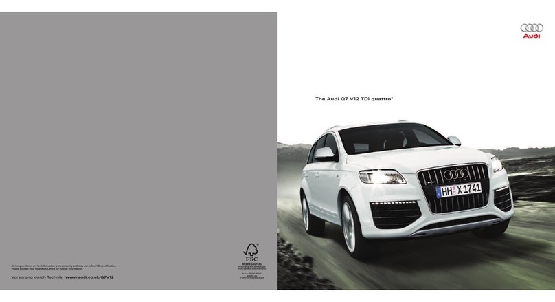
Audi Q7 2007 Operating instructions

Protected by copyright. Copying for private or commercial purposes, in part or in whole, is not
permitted unless authorised by AUDI AG. AUDI AG does not guarantee or accept any liability
with respect to the correctness of information in this document. Copyright by AUDI AG.
Repair Manual
Audi Q7 2007 ➤
Brake System
Engine ID BAR BHK CAT
A
CJW
C
CJW
B
CJW
E
CNR
B
CTW
B
CTW
A
Edition 03.2018
Service
Service Department. Technical Information

Protected by copyright. Copying for private or commercial purposes, in part or in whole, is not
permitted unless authorised by AUDI AG. AUDI AG does not guarantee or accept any liability
with respect to the correctness of information in this document. Copyright by AUDI AG.
List of Workshop Manual Repair Groups
Repair Group
00 - General, Technical Data
45 - Antilock Brake System
46 - Mechanical Components
47 - Hydraulic Components
Technical information should always be available to the foremen and mechanics, because their
careful and constant adherence to the instructions is essential to ensure vehicle road-worthiness and
safety. In addition, the normal basic safety precautions for working on motor vehicles must, as a
matter of course, be observed.
Service
All rights reserved.
No reproduction without prior agreement from publisher.
Copyright © 2018 Audi AG, Ingolstadt D3E80022530

Protected by copyright. Copying for private or commercial purposes, in part or in whole, is not
permitted unless authorised by AUDI AG. AUDI AG does not guarantee or accept any liability
with respect to the correctness of information in this document. Copyright by AUDI AG.
Contents
00 - General, Technical Data . . . . . . . . . . . . . . . . . . . . . . . . . . . . . . . . . . . . . . . . . . . . 1
1 Brake Allocation of PR Codes . . . . . . . . . . . . . . . . . . . . . . . . . . . . . . . . . . . . . . . . . . . . . . 1
1.1 General Information . . . . . . . . . . . . . . . . . . . . . . . . . . . . . . . . . . . . . . . . . . . . . . . . . . . . . . 1
1.2 Sample Vehicle Data Label . . . . . . . . . . . . . . . . . . . . . . . . . . . . . . . . . . . . . . . . . . . . . . . . 1
1.3 Brakes, Specifications . . . . . . . . . . . . . . . . . . . . . . . . . . . . . . . . . . . . . . . . . . . . . . . . . . . . 1
2 Ceramic Brake Rotor, Evaluating . . . . . . . . . . . . . . . . . . . . . . . . . . . . . . . . . . . . . . . . . . . . 6
2.1 Evaluating . . . . . . . . . . . . . . . . . . . . . . . . . . . . . . . . . . . . . . . . . . . . . . . . . . . . . . . . . . . . . . 6
2.2 Visual Characteristics of Ceramic Brake Rotors . . . . . . . . . . . . . . . . . . . . . . . . . . . . . . . . 7
2.3 Surface Cracks in Cooling Duct Crosspieces . . . . . . . . . . . . . . . . . . . . . . . . . . . . . . . . . . . . 7
2.4 Cracks in Ceramic Brake Rotor Connection Area . . . . . . . . . . . . . . . . . . . . . . . . . . . . . . . . 8
2.5 Chamfer . . . . . . . . . . . . . . . . . . . . . . . . . . . . . . . . . . . . . . . . . . . . . . . . . . . . . . . . . . . . . . . . 8
2.6 Nicks on Ceramic Brake Rotor . . . . . . . . . . . . . . . . . . . . . . . . . . . . . . . . . . . . . . . . . . . . . . 9
2.7 Crack in Cooling Duct . . . . . . . . . . . . . . . . . . . . . . . . . . . . . . . . . . . . . . . . . . . . . . . . . . . . . . 9
3 Ceramic Brake Rotor, Determining Wear . . . . . . . . . . . . . . . . . . . . . . . . . . . . . . . . . . . . . . 10
3.1 Determining Wear . . . . . . . . . . . . . . . . . . . . . . . . . . . . . . . . . . . . . . . . . . . . . . . . . . . . . . . . 10
3.2 Brake Rotor Thickness, Checking . . . . . . . . . . . . . . . . . . . . . . . . . . . . . . . . . . . . . . . . . . . . 14
3.3 Brake Rotor Thickness, Checking . . . . . . . . . . . . . . . . . . . . . . . . . . . . . . . . . . . . . . . . . . . . 15
3.4 Wear Indicators, Checking . . . . . . . . . . . . . . . . . . . . . . . . . . . . . . . . . . . . . . . . . . . . . . . . . . 16
3.5 Brake Rotor, Weighing . . . . . . . . . . . . . . . . . . . . . . . . . . . . . . . . . . . . . . . . . . . . . . . . . . . . 16
3.6 Ceramic Brake Rotor, Determining Wear using Carbon-Ceramic Brake Wear Tester
VAS6813 . . . . . . . . . . . . . . . . . . . . . . . . . . . . . . . . . . . . . . . . . . . . . . . . . . . . . . . . . . . . . . 18
4 Brakes Inspection . . . . . . . . . . . . . . . . . . . . . . . . . . . . . . . . . . . . . . . . . . . . . . . . . . . . . . . . 25
4.1 General Information . . . . . . . . . . . . . . . . . . . . . . . . . . . . . . . . . . . . . . . . . . . . . . . . . . . . . . 25
4.2 Checking . . . . . . . . . . . . . . . . . . . . . . . . . . . . . . . . . . . . . . . . . . . . . . . . . . . . . . . . . . . . . . 25
45 - Antilock Brake System . . . . . . . . . . . . . . . . . . . . . . . . . . . . . . . . . . . . . . . . . . . . . . 26
1 General Information . . . . . . . . . . . . . . . . . . . . . . . . . . . . . . . . . . . . . . . . . . . . . . . . . . . . . . 26
1.1 Antilock Brake System . . . . . . . . . . . . . . . . . . . . . . . . . . . . . . . . . . . . . . . . . . . . . . . . . . . . 26
1.2 Repair Information . . . . . . . . . . . . . . . . . . . . . . . . . . . . . . . . . . . . . . . . . . . . . . . . . . . . . . . . 26
2 Vehicle Diagnostic Tester , Connecting and Selection Functions . . . . . . . . . . . . . . . . . . . . 28
3 ABS Brake System, Components and Locations . . . . . . . . . . . . . . . . . . . . . . . . . . . . . . . . 29
4 Hydraulic Unit and Brake Booster/Brake Master Cylinder . . . . . . . . . . . . . . . . . . . . . . . . . . 32
4.1 Overview . . . . . . . . . . . . . . . . . . . . . . . . . . . . . . . . . . . . . . . . . . . . . . . . . . . . . . . . . . . . . . 32
4.2 ABS Control Module J104 with Hydraulic Unit, Removing and Installing . . . . . . . . . . . . . . 34
5 ABS Components on Front and Rear Axles . . . . . . . . . . . . . . . . . . . . . . . . . . . . . . . . . . . . 38
5.1 Front Axle, Overview . . . . . . . . . . . . . . . . . . . . . . . . . . . . . . . . . . . . . . . . . . . . . . . . . . . . . . 38
5.2 Speed Sensor on the Front Axle, Removing and Installing . . . . . . . . . . . . . . . . . . . . . . . . 38
5.3 Rear Axle, Overview . . . . . . . . . . . . . . . . . . . . . . . . . . . . . . . . . . . . . . . . . . . . . . . . . . . . . . 39
5.4 Speed Sensor on Rear Axle, Removing and Installing . . . . . . . . . . . . . . . . . . . . . . . . . . . . 39
6 Electronic Stabilization Program Components . . . . . . . . . . . . . . . . . . . . . . . . . . . . . . . . . . 41
6.1 ESP Sensor Unit G419 , Removing and Installing . . . . . . . . . . . . . . . . . . . . . . . . . . . . . . . . 41
6.2 Steering Angle Sensor G85 , Removing and Installing . . . . . . . . . . . . . . . . . . . . . . . . . . . . 42
7 Special Tools . . . . . . . . . . . . . . . . . . . . . . . . . . . . . . . . . . . . . . . . . . . . . . . . . . . . . . . . . . . . 43
46 - Mechanical Components . . . . . . . . . . . . . . . . . . . . . . . . . . . . . . . . . . . . . . . . . . . . 44
1 Front Brakes (PR - 1LF) . . . . . . . . . . . . . . . . . . . . . . . . . . . . . . . . . . . . . . . . . . . . . . . . . . . . 44
1.1 Servicing . . . . . . . . . . . . . . . . . . . . . . . . . . . . . . . . . . . . . . . . . . . . . . . . . . . . . . . . . . . . . . . . 44
1.2 Brake Pads, Removing and Installing . . . . . . . . . . . . . . . . . . . . . . . . . . . . . . . . . . . . . . . . 45
1.3 Brake Caliper, Removing and Installing . . . . . . . . . . . . . . . . . . . . . . . . . . . . . . . . . . . . . . . . 48
2 Front Brakes (PR- 1LT and 1LU) . . . . . . . . . . . . . . . . . . . . . . . . . . . . . . . . . . . . . . . . . . . . 50
2.1 Overview . . . . . . . . . . . . . . . . . . . . . . . . . . . . . . . . . . . . . . . . . . . . . . . . . . . . . . . . . . . . . . 50
Audi Q7 2007 ➤
Brake System - Edition 03.2018
Contents i

Protected by copyright. Copying for private or commercial purposes, in part or in whole, is not
permitted unless authorised by AUDI AG. AUDI AG does not guarantee or accept any liability
with respect to the correctness of information in this document. Copyright by AUDI AG.
2.2 Brake Pads, Removing and Installing . . . . . . . . . . . . . . . . . . . . . . . . . . . . . . . . . . . . . . . . 51
2.3 Front Brake Caliper, Removing and Installing . . . . . . . . . . . . . . . . . . . . . . . . . . . . . . . . . . 55
2.4 Front Brake Caliper, Removing and Installing . . . . . . . . . . . . . . . . . . . . . . . . . . . . . . . . . . 57
3 Front Brakes (PR- 1LW and 1LN) . . . . . . . . . . . . . . . . . . . . . . . . . . . . . . . . . . . . . . . . . . . . 59
3.1 Overview . . . . . . . . . . . . . . . . . . . . . . . . . . . . . . . . . . . . . . . . . . . . . . . . . . . . . . . . . . . . . . 59
3.2 Front Brake Caliper, Removing and Installing . . . . . . . . . . . . . . . . . . . . . . . . . . . . . . . . . . 62
3.3 Front Brake Caliper, Removing and Installing . . . . . . . . . . . . . . . . . . . . . . . . . . . . . . . . . . 64
3.4 Front Brake Pads, Removing and Installing . . . . . . . . . . . . . . . . . . . . . . . . . . . . . . . . . . . . 67
3.5 Front Brake Rotor, Removing and Installing . . . . . . . . . . . . . . . . . . . . . . . . . . . . . . . . . . . . 72
3.6 Front Brake Rotor, Removing and Installing . . . . . . . . . . . . . . . . . . . . . . . . . . . . . . . . . . . . 73
4 Rear Brakes (PR 1KF and 2EA) . . . . . . . . . . . . . . . . . . . . . . . . . . . . . . . . . . . . . . . . . . . . . . 75
4.1 Overview . . . . . . . . . . . . . . . . . . . . . . . . . . . . . . . . . . . . . . . . . . . . . . . . . . . . . . . . . . . . . . 75
4.2 Brake Rotor, Removing and Installing . . . . . . . . . . . . . . . . . . . . . . . . . . . . . . . . . . . . . . . . 77
4.3 Brake Pads, Removing and Installing . . . . . . . . . . . . . . . . . . . . . . . . . . . . . . . . . . . . . . . . 78
4.4 Brake Caliper, Removing and Installing . . . . . . . . . . . . . . . . . . . . . . . . . . . . . . . . . . . . . . . . 81
5 Rear Brakes (PR- 1KD) . . . . . . . . . . . . . . . . . . . . . . . . . . . . . . . . . . . . . . . . . . . . . . . . . . . . 83
5.1 Overview . . . . . . . . . . . . . . . . . . . . . . . . . . . . . . . . . . . . . . . . . . . . . . . . . . . . . . . . . . . . . . 83
5.2 Brake Rotor, Removing and Installing . . . . . . . . . . . . . . . . . . . . . . . . . . . . . . . . . . . . . . . . 84
5.3 Brake Pads, Removing and Installing . . . . . . . . . . . . . . . . . . . . . . . . . . . . . . . . . . . . . . . . 85
5.4 Brake Caliper, Removing and Installing . . . . . . . . . . . . . . . . . . . . . . . . . . . . . . . . . . . . . . . . 88
5.5 Brake Caliper, Removing and Installing . . . . . . . . . . . . . . . . . . . . . . . . . . . . . . . . . . . . . . . . 90
6 Rear Brakes (PR 2 EF and 1KK) . . . . . . . . . . . . . . . . . . . . . . . . . . . . . . . . . . . . . . . . . . . . 92
6.1 Overview . . . . . . . . . . . . . . . . . . . . . . . . . . . . . . . . . . . . . . . . . . . . . . . . . . . . . . . . . . . . . . 92
6.2 Brake Rotor, Removing and Installing . . . . . . . . . . . . . . . . . . . . . . . . . . . . . . . . . . . . . . . . 95
6.3 Brake Rotor, Removing and Installing . . . . . . . . . . . . . . . . . . . . . . . . . . . . . . . . . . . . . . . . 95
6.4 Brake Pads, Removing and Installing . . . . . . . . . . . . . . . . . . . . . . . . . . . . . . . . . . . . . . . . 96
6.5 Brakes Caliper, Removing and Installing . . . . . . . . . . . . . . . . . . . . . . . . . . . . . . . . . . . . . . 100
6.6 Brake Caliper, Removing and Installing . . . . . . . . . . . . . . . . . . . . . . . . . . . . . . . . . . . . . . . . 102
7 Brake Shoes, Removing and Installing . . . . . . . . . . . . . . . . . . . . . . . . . . . . . . . . . . . . . . . . 105
8 Parking Brake (Basic Setting) . . . . . . . . . . . . . . . . . . . . . . . . . . . . . . . . . . . . . . . . . . . . . . 109
9 Free Play of Foot Operated Parking Brake, Checking . . . . . . . . . . . . . . . . . . . . . . . . . . . . 111
10 Brake Shoes, Running-In on Brake Test Stand . . . . . . . . . . . . . . . . . . . . . . . . . . . . . . . . . . 112
11 Brake Shoes, Burnishing on a Blocked Off Street . . . . . . . . . . . . . . . . . . . . . . . . . . . . . . . . 113
12 Pedal Parking Brake . . . . . . . . . . . . . . . . . . . . . . . . . . . . . . . . . . . . . . . . . . . . . . . . . . . . . . 114
12.1 Pedal Parking Brake Lever Overview . . . . . . . . . . . . . . . . . . . . . . . . . . . . . . . . . . . . . . . . . . 114
12.2 Pedal Parking Brake Lever, Removing and Installing . . . . . . . . . . . . . . . . . . . . . . . . . . . . 114
12.3 Foot Operated Parking Brake Gas-Filled Strut, Removing and Installing . . . . . . . . . . . . . . 116
12.4 Transfer Module Overview . . . . . . . . . . . . . . . . . . . . . . . . . . . . . . . . . . . . . . . . . . . . . . . . . . 117
13 Brake Cables . . . . . . . . . . . . . . . . . . . . . . . . . . . . . . . . . . . . . . . . . . . . . . . . . . . . . . . . . . . . 118
13.1 Overview . . . . . . . . . . . . . . . . . . . . . . . . . . . . . . . . . . . . . . . . . . . . . . . . . . . . . . . . . . . . . . 118
13.2 Rear Brake Cables, Removing and Installing . . . . . . . . . . . . . . . . . . . . . . . . . . . . . . . . . . . . 118
13.3 Brake Cable, Disengaging from Spreader . . . . . . . . . . . . . . . . . . . . . . . . . . . . . . . . . . . . . . 119
13.4 Front Brake Cable, Removing and Installing . . . . . . . . . . . . . . . . . . . . . . . . . . . . . . . . . . . . 120
14 Brake Pedal . . . . . . . . . . . . . . . . . . . . . . . . . . . . . . . . . . . . . . . . . . . . . . . . . . . . . . . . . . . . 122
14.1 Overview . . . . . . . . . . . . . . . . . . . . . . . . . . . . . . . . . . . . . . . . . . . . . . . . . . . . . . . . . . . . . . 122
14.2 Brake Pedal, Removing and Installing . . . . . . . . . . . . . . . . . . . . . . . . . . . . . . . . . . . . . . . . 123
14.3 Brake Light Switch (Old Generation) . . . . . . . . . . . . . . . . . . . . . . . . . . . . . . . . . . . . . . . . . . 124
14.4 Brake Light Switch (New Generation) . . . . . . . . . . . . . . . . . . . . . . . . . . . . . . . . . . . . . . . . 125
14.5 Brake Pedal and Brake Booster, Separating and Connecting . . . . . . . . . . . . . . . . . . . . . . 127
14.6 Brake Pedal, Attaching to Brake Booster . . . . . . . . . . . . . . . . . . . . . . . . . . . . . . . . . . . . . . 128
14.7 Mount, Removing and Installing, Brake Booster Push Rod . . . . . . . . . . . . . . . . . . . . . . . . 128
15 Special Tools . . . . . . . . . . . . . . . . . . . . . . . . . . . . . . . . . . . . . . . . . . . . . . . . . . . . . . . . . . . . 130
47 - Hydraulic Components . . . . . . . . . . . . . . . . . . . . . . . . . . . . . . . . . . . . . . . . . . . . . . 133
Audi Q7 2007 ➤
Brake System - Edition 03.2018
ii Contents

Protected by copyright. Copying for private or commercial purposes, in part or in whole, is not
permitted unless authorised by AUDI AG. AUDI AG does not guarantee or accept any liability
with respect to the correctness of information in this document. Copyright by AUDI AG.
1 Brake Caliper (PR - 1LT and 1LU) . . . . . . . . . . . . . . . . . . . . . . . . . . . . . . . . . . . . . . . . . . . . 133
1.1 Overview . . . . . . . . . . . . . . . . . . . . . . . . . . . . . . . . . . . . . . . . . . . . . . . . . . . . . . . . . . . . . . 133
1.2 Brake Caliper Piston, Removing and Installing . . . . . . . . . . . . . . . . . . . . . . . . . . . . . . . . . . 133
2 Brake Caliper (PR - 1LF) . . . . . . . . . . . . . . . . . . . . . . . . . . . . . . . . . . . . . . . . . . . . . . . . . . 136
2.1 Overview . . . . . . . . . . . . . . . . . . . . . . . . . . . . . . . . . . . . . . . . . . . . . . . . . . . . . . . . . . . . . . 136
2.2 Brake Caliper Piston, Removing and Installing, PR- 1LF . . . . . . . . . . . . . . . . . . . . . . . . . . 137
3 Brake Caliper (PR- 1LW and 1LN) . . . . . . . . . . . . . . . . . . . . . . . . . . . . . . . . . . . . . . . . . . . . 139
3.1 Overview . . . . . . . . . . . . . . . . . . . . . . . . . . . . . . . . . . . . . . . . . . . . . . . . . . . . . . . . . . . . . . 139
3.2 Front Ceramic Brake Caliper Piston, Removing and Installing . . . . . . . . . . . . . . . . . . . . . . 140
4 Rear Brake Caliper . . . . . . . . . . . . . . . . . . . . . . . . . . . . . . . . . . . . . . . . . . . . . . . . . . . . . . . . 143
4.1 Overview . . . . . . . . . . . . . . . . . . . . . . . . . . . . . . . . . . . . . . . . . . . . . . . . . . . . . . . . . . . . . . 143
4.2 Rear Brake Caliper, Removing and Installing, all Models . . . . . . . . . . . . . . . . . . . . . . . . . . 144
5 Pressure Leak Test . . . . . . . . . . . . . . . . . . . . . . . . . . . . . . . . . . . . . . . . . . . . . . . . . . . . . . 146
6 Brake System, Bleeding . . . . . . . . . . . . . . . . . . . . . . . . . . . . . . . . . . . . . . . . . . . . . . . . . . . . 147
6.1 Brake System, Bleeding with Brake Charger/Bleed Unit . . . . . . . . . . . . . . . . . . . . . . . . . . 147
6.2 Pre-Bleeding . . . . . . . . . . . . . . . . . . . . . . . . . . . . . . . . . . . . . . . . . . . . . . . . . . . . . . . . . . . . 148
6.3 Hydraulic System, Bleeding without Brake Charger/Bleeder Unit . . . . . . . . . . . . . . . . . . . . 149
6.4 Brake Fluid, Changing . . . . . . . . . . . . . . . . . . . . . . . . . . . . . . . . . . . . . . . . . . . . . . . . . . . . 151
7 Brake Booster/Master Brake Cylinder . . . . . . . . . . . . . . . . . . . . . . . . . . . . . . . . . . . . . . . . 152
7.1 Overview . . . . . . . . . . . . . . . . . . . . . . . . . . . . . . . . . . . . . . . . . . . . . . . . . . . . . . . . . . . . . . 152
7.2 Brake Master Cylinder, Removing and Installing . . . . . . . . . . . . . . . . . . . . . . . . . . . . . . . . 153
7.3 Brake Booster, Removing and Installing . . . . . . . . . . . . . . . . . . . . . . . . . . . . . . . . . . . . . . 154
7.4 Brake Booster Push Rod Mount, Removing and Installing . . . . . . . . . . . . . . . . . . . . . . . . 156
8 Brake Booster Vacuum Pump . . . . . . . . . . . . . . . . . . . . . . . . . . . . . . . . . . . . . . . . . . . . . . 159
8.1 Vacuum Pump, Diesel, Overview . . . . . . . . . . . . . . . . . . . . . . . . . . . . . . . . . . . . . . . . . . . . 159
8.2 Overview - Vacuum Pump, Vehicles with 3.0L TFSI Engine . . . . . . . . . . . . . . . . . . . . . . . . 160
8.3 Vacuum Pump, 4.2L Diesel, Removing and Installing . . . . . . . . . . . . . . . . . . . . . . . . . . . . 160
8.4 Vacuum Pump, Removing and Installing, 3.0L TDI Engine . . . . . . . . . . . . . . . . . . . . . . . . 163
8.5 Vacuum Pump, Removing and Installing, 12 Cylinder TDI Engine . . . . . . . . . . . . . . . . . . 164
8.6 Vacuum Pump, Removing and Installing, 3.0L TFSI Engine . . . . . . . . . . . . . . . . . . . . . . . . 165
9 Electrical Brake System Vacuum Pump V192 . . . . . . . . . . . . . . . . . . . . . . . . . . . . . . . . . . 167
9.1 Overview . . . . . . . . . . . . . . . . . . . . . . . . . . . . . . . . . . . . . . . . . . . . . . . . . . . . . . . . . . . . . . 167
9.2 Brake System Vacuum Pump V192 , Removing and Installing . . . . . . . . . . . . . . . . . . . . . . 167
9.3 Brake Booster Pressure Sensor G294 , Removing and Installing . . . . . . . . . . . . . . . . . . . . 168
9.4 Check Valve, Checking . . . . . . . . . . . . . . . . . . . . . . . . . . . . . . . . . . . . . . . . . . . . . . . . . . . . 168
10 Brake Lines . . . . . . . . . . . . . . . . . . . . . . . . . . . . . . . . . . . . . . . . . . . . . . . . . . . . . . . . . . . . 169
10.1 Repairing . . . . . . . . . . . . . . . . . . . . . . . . . . . . . . . . . . . . . . . . . . . . . . . . . . . . . . . . . . . . . . 169
10.2 Flaring Tool Overview . . . . . . . . . . . . . . . . . . . . . . . . . . . . . . . . . . . . . . . . . . . . . . . . . . . . 169
10.3 Flaring Tool Instructions . . . . . . . . . . . . . . . . . . . . . . . . . . . . . . . . . . . . . . . . . . . . . . . . . . . . 170
11 Special Tools . . . . . . . . . . . . . . . . . . . . . . . . . . . . . . . . . . . . . . . . . . . . . . . . . . . . . . . . . . . . 173
12 Revision History . . . . . . . . . . . . . . . . . . . . . . . . . . . . . . . . . . . . . . . . . . . . . . . . . . . . . . . . . . 175
Audi Q7 2007 ➤
Brake System - Edition 03.2018
Contents iii

Protected by copyright. Copying for private or commercial purposes, in part or in whole, is not
permitted unless authorised by AUDI AG. AUDI AG does not guarantee or accept any liability
with respect to the correctness of information in this document. Copyright by AUDI AG.
Audi Q7 2007 ➤
Brake System - Edition 03.2018
iv Contents

Protected by copyright. Copying for private or commercial purposes, in part or in whole, is not
permitted unless authorised by AUDI AG. AUDI AG does not guarantee or accept any liability
with respect to the correctness of information in this document. Copyright by AUDI AG.
00 – General, Technical Data
1 Brake Allocation of PR Codes
(Edition 03.2018)
⇒ “1.1 General Information”, page 1
⇒ “1.2 Sample Vehicle Data Label”, page 1
⇒ “1.3 Brakes, Specifications”, page 1
1.1 General Information
The ABS brake system is divided diagonally (two circuits). The
brake booster is pneumatically controlled by the vacuum brake
booster.
The brake system installed in a vehicle is documented on the ve‐
hicle data sticker via the relevant PR number.
1.2 Sample Vehicle Data Label
The following brakes are installed in this example:
♦ Arrow -A- model.
♦ Arrow -B- front brakes -1LF.
♦ Arrow -C- rear brakes - 1KF.
The vehicle data label can be found in the spare wheel well as
well as in the Maintenance booklet.
The following table shows the meaning of the PR numbers. These
are important for combination brake caliper/brake disc/brake
drum and brake pad.
♦ Allocation. Refer to the Parts Catalog.
1.3 Brakes, Specifications
Note
♦
Hairline cracks on brake rotor friction surfaces are often ob‐
served during brake repairs. Hairline cracks up to 10 mm long
are not a technical flaw and are not cause for brake rotor re‐
placement.
♦
Brake rotors with friction surfaces that have worn through
should be replaced.
Front Brakes, 18" Brembo
Production Number.
PR-Nr
1LF
Brake caliper Brembo 18“
Brake pad, thickness,
without backing plate
mm 11
Brake pad, wear limit
without back plate
mm 2
Brake rotor di‐
ame‐
ter in
mm
350 mm
Brake rotor, thickness mm 34
Audi Q7 2007 ➤
Brake System - Edition 03.2018
1. Brake Allocation of PR Codes 1

Protected by copyright. Copying for private or commercial purposes, in part or in whole, is not
permitted unless authorised by AUDI AG. AUDI AG does not guarantee or accept any liability
with respect to the correctness of information in this document. Copyright by AUDI AG.
Front Brakes, 18" Brembo
Brake rotor, wear limit mm 32
Brake caliper, 6 pis‐
tons
di‐
ame‐
ter in
mm
every 2 x 30/ 34/ 38 mm
Note
♦
Maximum lateral run-out of steel brake rotor = 0.06 mm
♦
Measurement in installed brake rotor
♦
Use Dial Indicator Bracket - VAS 6079/1; Dial Indicator -
0-10mm - VAS 6079.
♦
Clean dirt and rust off the brake rotor.
♦
Measure 10 mm away from the outer edge of the brake rotor.
⇒ “1 Front Brakes (PR - 1LF)”, page 44
Note
♦
Hairline cracks on brake rotor friction surfaces are often ob‐
served during brake repairs. Hairline cracks up to 10 mm long
are not a technical flaw and are not cause for brake rotor re‐
placement.
♦
Brake rotors with friction surfaces that have worn through
should be replaced.
Brembo Front Brakes (18 Inch Plus)
Production Number.
PR-Nr
1LT
Brake caliper Brembo 18“ Plus
Brake pad, thickness,
without backing plate
mm 11
Brake pad, wear limit
without back plate
mm 2
Brake rotor di‐
ame‐
ter in
mm
368 mm
Brake rotor, thickness mm 36
Brake rotor, wear limit mm 34
Brake caliper, 6 pis‐
tons
di‐
ame‐
ter in
mm
each 36 mm
Audi Q7 2007 ➤
Brake System - Edition 03.2018
2 Rep. Gr.00 - General, Technical Data

Protected by copyright. Copying for private or commercial purposes, in part or in whole, is not
permitted unless authorised by AUDI AG. AUDI AG does not guarantee or accept any liability
with respect to the correctness of information in this document. Copyright by AUDI AG.
Note
♦
Maximum lateral run-out of steel brake rotor = 0.06 mm
♦
Measurement in installed brake rotor
♦
Use Dial Indicator Bracket - VAS 6079/1; Dial Indicator -
0-10mm - VAS 6079.
♦
Clean dirt and rust off the brake rotor.
♦
Measure 10 mm away from the outer edge of the brake rotor.
⇒ “2 Front Brakes (PR- 1LT and 1LU)”, page 50
Note
♦
Hairline cracks on brake rotor friction surfaces are often ob‐
served during brake repairs. Hairline cracks up to 10 mm long
are not a technical flaw and are not cause for brake rotor re‐
placement.
♦
Brake rotors with friction surfaces that have worn through
should be replaced.
Ceramic Front Brakes
Production-relevant
number (PR number)
1LN / 1LW
Brake caliper Alcon 8K (20”)
Brake rotor ventilated di‐
ame‐
ter
mm
420
Brake rotor, thickness mm 40
Brake rotor, wear limit The wear value is the minimum
brake disc thickness during man‐
ufacturing and is stamped into
the brake disc cup.
Brake caliper, 8 pis‐
tons
di‐
ame‐
ter
mm
8 x diameter 30,2
Brake pad thickness
with backing plate
mm 20
Brake pad wear limit
with backing plate
mm 10
⇒ “3 Front Brakes (PR- 1LW and 1LN)”, page 59
Note
Hairline cracks on the friction surface on ceramic brakes occur
during the manufacturing process and can be found on new
brakes in different stampings. Hairline cracks on the friction sur‐
faces are not a reason to exchange the ceramic brake rotors.
Rear Brakes (Disc Brakes 17" and 18")
Production Number.
PR-Nr
1KF 2EA
Audi Q7 2007 ➤
Brake System - Edition 03.2018
1. Brake Allocation of PR Codes 3

Protected by copyright. Copying for private or commercial purposes, in part or in whole, is not
permitted unless authorised by AUDI AG. AUDI AG does not guarantee or accept any liability
with respect to the correctness of information in this document. Copyright by AUDI AG.
Rear Brakes (Disc Brakes 17" and 18")
Brake caliper Brembo (17") Brembo
(18")
Brake pad, thickness mm 11 11
Brake pad, wear limit
without back plate
mm 2 2
Brake rotor di‐
ame‐
ter in
mm
330 358
Brake rotor, thickness mm 28 28
Brake rotor, wear limit mm 26 26
Brake caliper, 4 pis‐
tons
di‐
ame‐
ter
mm
each 2 x 28/ 30 each 30
Note
♦
Maximum lateral run-out of steel brake rotor = 0.06 mm
♦
Measurement in installed brake rotor
♦
Use Dial Indicator Bracket - VAS 6079/1; Dial Indicator -
0-10mm - VAS 6079.
♦
Clean dirt and rust off the brake rotor.
♦
Measure 10 mm away from the outer edge of the brake rotor.
⇒ “4 Rear Brakes (PR 1KF and 2EA)”, page 75
Rear Wheel Brake, (Disc Brake 18" Plus)
Production Number.
PR-Nr
1KD
Brake caliper Brembo (18")
Brake pad, thickness mm 11
Brake pad, wear limit
without back plate
mm 2
Brake rotor di‐
ame‐
ter in
mm
358
Brake rotor, thickness mm 28
Brake rotor, wear limit mm 26
Brake caliper, 4 pis‐
tons
di‐
ame‐
ter in
mm
each 30
Audi Q7 2007 ➤
Brake System - Edition 03.2018
4 Rep. Gr.00 - General, Technical Data

Protected by copyright. Copying for private or commercial purposes, in part or in whole, is not
permitted unless authorised by AUDI AG. AUDI AG does not guarantee or accept any liability
with respect to the correctness of information in this document. Copyright by AUDI AG.
Note
♦
Maximum lateral run-out of steel brake rotor = 0.06 mm
♦
Measurement in installed brake rotor
♦
Use Dial Indicator Bracket - VAS 6079/1; Dial Indicator -
0-10mm - VAS 6079.
♦
Clean dirt and rust off the brake rotor.
♦
Measure 10 mm away from the outer edge of the brake rotor.
⇒ “5 Rear Brakes (PR- 1KD)”, page 83
Ceramic - Rear Brakes
Brake caliper TRW C45 EPB (20”)
Production-relevant
number (PR number)
1KK / 2EF
Brake rotor ventilated di‐
ame‐
ter
mm
356
Brake rotor, thickness mm 28
Brake rotor, wear limit The wear value is the minimum
brake disc thickness during man‐
ufacturing and is stamped into
the brake disc cup.
Brake caliper, 1 pis‐
tons
di‐
ame‐
ter
mm
45
Brake pad thickness
with backing plate
mm 16.9
Brake pad wear limit
with backing plate
mm 9
⇒ “6 Rear Brakes (PR 2 EF and 1KK)”, page 92
Parking Brake, Drum Brake
Brake drum di‐
ame‐
ter in
mm
210
Brake drum, wear limit di‐
ame‐
ter in
mm
211
Brake pad, thickness mm 30
Brake pad, remaining
thickness
mm 5.5
Hairline cracks on the friction surface on ceramic brakes occur
during the manufacturing process and can be found on new
brakes in different stampings. Hairline cracks on the friction sur‐
faces are not a reason to exchange the ceramic brake rotors.
Audi Q7 2007 ➤
Brake System - Edition 03.2018
1. Brake Allocation of PR Codes 5

Protected by copyright. Copying for private or commercial purposes, in part or in whole, is not
permitted unless authorised by AUDI AG. AUDI AG does not guarantee or accept any liability
with respect to the correctness of information in this document. Copyright by AUDI AG.
2 Ceramic Brake Rotor, Evaluating
⇒ “2.1 Evaluating”, page 6
⇒ “2.2 Visual Characteristics of Ceramic Brake Rotors”,
page 7
⇒ “2.3 Surface Cracks in Cooling Duct Crosspieces”, page 7
⇒ “2.4 Cracks in Ceramic Brake Rotor Connection Area”,
page 8
⇒ “2.5 Chamfer”, page 8
⇒ “2.6 Nicks on Ceramic Brake Rotor”, page 9
⇒ “2.7 Crack in Cooling Duct”, page 9
2.1 Evaluating
1 - Cooling Channels
2 - Friction Surface
3 - Base Material
Audi Q7 2007 ➤
Brake System - Edition 03.2018
6 Rep. Gr.00 - General, Technical Data

Protected by copyright. Copying for private or commercial purposes, in part or in whole, is not
permitted unless authorised by AUDI AG. AUDI AG does not guarantee or accept any liability
with respect to the correctness of information in this document. Copyright by AUDI AG.
2.2 Visual Characteristics of Ceramic Brake
Rotors
Checking threaded connectors on the brake rotor ring and brake
rotor cup:
WARNING
The brake rotor ring and the brake rotor cup are attached to
each other and must never be separated. Never loosen the
threaded connector on the brake rotor cup.
The friction surface on a new brake rotor already has stress
cracks made during the production process. These stress cracks
are all different.
Note
Stress cracks do not mean the ceramic brake rotor is faulty.
The stress cracks are somewhat visible on new brake discs and
different from each other in strength.
2.3 Surface Cracks in Cooling Duct Cross‐
pieces
The cracks on the surface of the cooling channels -arrow- were
produced during the manufacturing process.
Note
The surface cracks do not mean the ceramic brake rotor is faulty.
Audi Q7 2007 ➤
Brake System - Edition 03.2018
2. Ceramic Brake Rotor, Evaluating 7

Protected by copyright. Copying for private or commercial purposes, in part or in whole, is not
permitted unless authorised by AUDI AG. AUDI AG does not guarantee or accept any liability
with respect to the correctness of information in this document. Copyright by AUDI AG.
2.4 Cracks in Ceramic Brake Rotor Connec‐
tion Area
Checking threaded connectors on the brake rotor ring and brake
rotor cup:
WARNING
The brake rotor ring and the brake rotor cup are attached to
each other and must never be separated. Never loosen the
threaded connector on the brake rotor cup.
If the ceramic brake rotor has cracks near the threaded connec‐
tors on the cup leading to the friction surface on the brake rotor
-arrows-, then the brake rotors must be replaced.
If the ceramic brake discs have radial cracks near the threaded
connectors on the brake disc cup, then the brake discs must be
replaced.
Always replace the brake rotors on both sides of the axle when:
♦ The brake discs must be replaced because they are worn.
♦ the replacement brake rotor has been technically modified,
which can be determined by the revised part number.
Note
♦
Brake rotors must always be replaced on both sides of the
axle.
♦
Brake pads likewise must always be replaced on both sides of
the axle.
2.5 Chamfer
Chips on the edge -arrow- of the brake rotor are caused by me‐
chanical damage.
The following are permitted:
♦ maximum width/depth = 2mm.
♦ maximum length = 20mm
♦ maximum number of chips on the brake rotor = 3
If any of these criteria are exceeded, replace the brake disc.
Always replace the brake rotors on both sides of the axle when:
♦ The brake discs must be replaced because they are worn.
♦ the replacement brake rotor has been technically modified,
which can be determined by the revised part number.
Note
♦
Brake rotors must always be replaced on both sides of the
axle.
♦
Brake pads likewise must always be replaced on both sides of
the axle.
Audi Q7 2007 ➤
Brake System - Edition 03.2018
8 Rep. Gr.00 - General, Technical Data

Protected by copyright. Copying for private or commercial purposes, in part or in whole, is not
permitted unless authorised by AUDI AG. AUDI AG does not guarantee or accept any liability
with respect to the correctness of information in this document. Copyright by AUDI AG.
2.6 Nicks on Ceramic Brake Rotor
If the ceramic brake disc starts to show material break down on
the friction surface greater than 1cm², -arrow- then the ceramic
brake discs must be replaced.
Always replace the brake rotors on both sides of the axle when:
♦ The brake discs must be replaced because they are worn.
♦ the replacement brake rotor has been technically modified,
which can be determined by the revised part number.
Note
♦
Brake rotors must always be replaced on both sides of the
axle.
♦
Brake pads likewise must always be replaced on both sides of
the axle.
2.7 Crack in Cooling Duct
If the ceramic brake rotor has a crack on the friction surface lead‐
ing to or through the cooling channel, the replace the ceramic
brake rotor.
Audi Q7 2007 ➤
Brake System - Edition 03.2018
2. Ceramic Brake Rotor, Evaluating 9

Protected by copyright. Copying for private or commercial purposes, in part or in whole, is not
permitted unless authorised by AUDI AG. AUDI AG does not guarantee or accept any liability
with respect to the correctness of information in this document. Copyright by AUDI AG.
3 Ceramic Brake Rotor, Determining
Wear
⇒ “3.1 Determining Wear”, page 10
⇒ “3.2 Brake Rotor Thickness, Checking”, page 14
⇒ “3.4 Wear Indicators, Checking”, page 16
⇒ “3.3 Brake Rotor Thickness, Checking”, page 15
⇒ “3.4 Wear Indicators, Checking”, page 16
⇒ “3.5 Brake Rotor, Weighing ”, page 16
⇒ “3.6 Ceramic Brake Rotor, Determining Wear using Carbon-
Ceramic Brake Wear Tester VAS6813 ”, page 18
3.1 Determining Wear
WARNING
The brake rotor ring and the brake rotor cup are attached to
each other and must never be separated. Never loosen the
threaded connector on the brake rotor cup.
Checking threaded connectors on the brake rotor ring and brake
rotor cup:
Identification on the ceramic brake rotor on the brake rotor cup
Audi Q7 2007 ➤
Brake System - Edition 03.2018
10 Rep. Gr.00 - General, Technical Data

Protected by copyright. Copying for private or commercial purposes, in part or in whole, is not
permitted unless authorised by AUDI AG. AUDI AG does not guarantee or accept any liability
with respect to the correctness of information in this document. Copyright by AUDI AG.
1 - Running Direction
2 - Supplier
3 - On-Going Brake Rotor Pro‐
duction Number
4 - Audi Part Number
Note
The Audi part number on the brake
rotor is an example and will be dif‐
ferent on each vehicle model.
5 - Production Date of the Ce‐
ramic Brake Rotor
6 - Minimum Permissible
Thickness
Note
The minimum permissible brake
disc thickness is different for each
vehicle model.
7 - New Ceramic Brake Rotor
and Cup Weight
Note
The weight of a new brake disc and
cup will be different on each vehicle
model.
Checking threaded connectors
on the brake rotor ring and
brake rotor cup:
WARNING
The brake rotor ring and
the brake rotor cup are
attached to each other
and must never be sep‐
arated. Never loosen the
threaded connector on
the brake rotor cup.
Note
Depending on the version, the min‐
imum weight of the driven brake ro‐
tor is stamped on the brake rotor
cup. If the stamped minimum weight
is reached or falls below, then the
brake rotor must be replaced. Al‐
ways replace brake rotors on both
sides of the axle.
Audi Q7 2007 ➤
Brake System - Edition 03.2018
3. Ceramic Brake Rotor, Determining Wear 11

Protected by copyright. Copying for private or commercial purposes, in part or in whole, is not
permitted unless authorised by AUDI AG. AUDI AG does not guarantee or accept any liability
with respect to the correctness of information in this document. Copyright by AUDI AG.
Caution
If the minimum weight of
the brake rotor “min.
weight” is displayed on
the brake rotor cup, then
the brake rotor must be
weighed to determine
additional wear.
Caution
Only brake rotors of the
same version may be in‐
stalled on an axle.
Note
Clean the brake rotor before determining the wear.
WARNING
Never clean the brake rotor with water or any other fluid. This
will make the measuring result incorrect.
Note
♦
The brake rotor vent holes must be free of brake dust and dirt.
It may be necessary to use something suitable to clean the
holes. Do not use force.
♦
Clean the brake rotor thoroughly with compressed air between
the cooling channels and the vent holes.
Caution
Always wear a mouth and nose mask when using compressed
air to clean the brake rotor and the brake system.
Perform the following to determine the brake rotor for wear:
♦ 1 Check the brake rotor thickness
♦ 2 Check the Wear Indicators
1 Check the brake rotor thickness. Refer to
⇒ “3.2 Brake Rotor Thickness, Checking”, page 14 .
If the brake rotor thickness is within the permissible range →
then the brake rotor is OK
the thickness of the brake ro‐
tor is in the critical range: min‐
imum Th + 0.2mm
when reaching or not reaching
the limit
↓↓ ↓↓
Wear indicators Replace brake rotor
Audi Q7 2007 ➤
Brake System - Edition 03.2018
12 Rep. Gr.00 - General, Technical Data

Protected by copyright. Copying for private or commercial purposes, in part or in whole, is not
permitted unless authorised by AUDI AG. AUDI AG does not guarantee or accept any liability
with respect to the correctness of information in this document. Copyright by AUDI AG.
↓↓ ----------
2 Use the wear indicators to check the brake rotor wear. Refer
to ⇒ “3.4 Wear Indicators, Checking”, page 16 .
If none of the six wear indicators are burned out → then the
brake rotor is OK.
---------- One of the six wear indicators is
completely burned out
--------- ↓↓
---------- Replace brake rotor
Note
Depending on the version, the minimum weight of the driven
brake rotor is stamped on the brake rotor cup. If the stamped
minimum weight is reached or falls below, then the brake rotor
must be replaced. Always replace brake rotors on both sides of
the axle.
Caution
If the minimum weight of the brake rotor “min. weight” is dis‐
played on the brake rotor cup, then the brake rotor must be
weighed to determine additional wear. If the minimum weight
is reached or falls below, then the brake rotor must be replaced.
Note
Brake rotor with stamped-on minimum weight.
Perform the following to determine the brake rotor for wear:
♦ 1 Check the brake rotor thickness
♦ 2 Check the Wear Indicators
♦ 3 Weigh the brake rotor
1 Checking for wear by testing the brake rotor thickness with
reference to the stamped-on minimum weight. Refer to
⇒ “3.3 Brake Rotor Thickness, Checking”, page 15 .
If the brake rotor thickness is within the permissible range →
then the brake rotor is OK
the thickness of the brake ro‐
tor is in the critical range: min‐
imum Th + 0.05 mm
when reaching or not reaching
the limit
↓↓ ↓↓
Wear indicators Replace brake rotor
↓↓ ----------
2 Use the wear indicators to check the brake rotor wear. Refer
to ⇒ “3.4 Wear Indicators, Checking”, page 16 .
If none of the six wear indicators are burned out → then the
brake rotor is OK.
---------- One of the six wear indicators is
completely burned out
--------- ↓↓
Audi Q7 2007 ➤
Brake System - Edition 03.2018
3. Ceramic Brake Rotor, Determining Wear 13

Protected by copyright. Copying for private or commercial purposes, in part or in whole, is not
permitted unless authorised by AUDI AG. AUDI AG does not guarantee or accept any liability
with respect to the correctness of information in this document. Copyright by AUDI AG.
---------- 3. Weigh the brake rotor. Refer
to
⇒ “3.5 Brake Rotor, Weighing ”,
page 16 .
---------- If the minimum weight is not
reached
---------- ↓↓
---------- The brake rotor is OK.
---------- If the minimum weight is
reached
---------- ↓↓
---------- Replace the brake rotor
Always replace the brake rotors on both sides of the axle when:
♦ The brake discs must be replaced because they are worn.
♦ the replacement brake rotor has been technically modified,
which can be determined by the revised part number.
Note
♦
If the brake rotors have reached or fall below the wear limit,
replace on both sides of the axle.
♦
Brake pads likewise must always be replaced on both sides of
the axle.
3.2 Brake Rotor Thickness, Checking
Special tools and workshop equipment required
♦ Use a commercially available caliper gauge or a micrometer
gauge.
Remove the brake rotors to measure the brake rotor thickness.
The minimum permissible brake disc thickness “min.Th.” is en‐
graved in the brake disc cup.
Audi Q7 2007 ➤
Brake System - Edition 03.2018
14 Rep. Gr.00 - General, Technical Data
Other manuals for Q7 2007
8
Table of contents
Other Audi Automobile manuals

Audi
Audi Q7 User manual

Audi
Audi AZ 2022 User manual

Audi
Audi TT Roadster 2018 User manual

Audi
Audi 100 1983 Instruction manual

Audi
Audi 2009 A5 Cabriolet User manual

Audi
Audi 2014 A8 User manual

Audi
Audi 2003 A8 Instruction manual

Audi
Audi Q5 2017 User manual

Audi
Audi 243 User manual

Audi
Audi TT 2012 User manual

Audi
Audi TT 2007 Operating instructions

Audi
Audi RS 5 Assembly instructions

Audi
Audi A3 2010 User manual

Audi
Audi A4 2015 Instruction manual

Audi
Audi Q5 2024 User manual

Audi
Audi A3 Sedan 2015 User manual

Audi
Audi A6 User manual

Audi
Audi A5 SPORTBACK User manual

Audi
Audi A3 2012 User manual

Audi
Audi A3 Sportback g-tron User manual