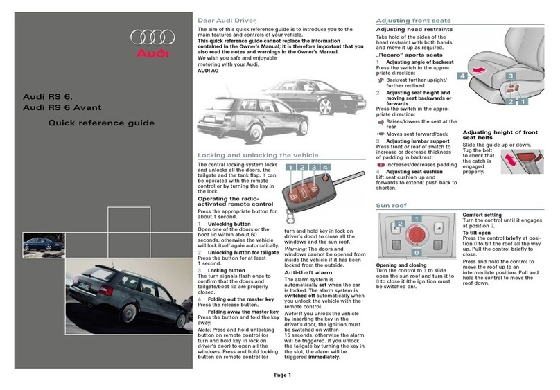
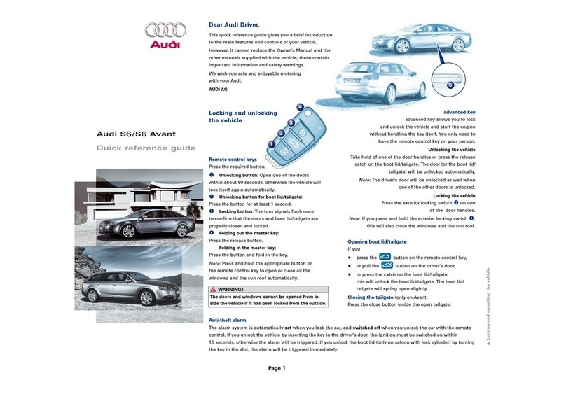
Audi Q7 2007 Operating instructions

Protected by copyright. Copying for private or commercial purposes, in part or in whole, is not
permitted unless authorised by AUDI AG. AUDI AG does not guarantee or accept any liability
with respect to the correctness of information in this document. Copyright by AUDI AG.
Repair Manual
Audi Q7 2007 ➤
Suspension, Wheels, Steering
Engine ID BAR BHK CAT
A
CNR
B
CJW
C
CJW
B
CJW
E
CTW
A
CTW
B
Edition 01.2014
Service
Service Department. Technical Information

Protected by copyright. Copying for private or commercial purposes, in part or in whole, is not
permitted unless authorised by AUDI AG. AUDI AG does not guarantee or accept any liability
with respect to the correctness of information in this document. Copyright by AUDI AG.
List of Workshop Manual Repair GroupsList of Workshop Manual
Repair GroupsList of Workshop Manual Repair Groups
Repair Group
00 - General, Technical Data
40 - Front Suspension
42 - Rear Suspension
43 - Self-Leveling Suspension
44 - Wheels, Tires, Wheel Alignment
48 - Steering
Technical information should always be available to the foremen and mechanics, because their
careful and constant adherence to the instructions is essential to ensure vehicle road-worthiness and
safety. In addition, the normal basic safety precautions for working on motor vehicles must, as a
matter of course, be observed.
Service
All rights reserved.
No reproduction without prior agreement from publisher.
Copyright © 2015 Audi AG, Ingolstadt D3E800230C9

Protected by copyright. Copying for private or commercial purposes, in part or in whole, is not
permitted unless authorised by AUDI AG. AUDI AG does not guarantee or accept any liability
with respect to the correctness of information in this document. Copyright by AUDI AG.
Contents
00 - General, Technical Data . . . . . . . . . . . . . . . . . . . . . . . . . . . . . . . . . . . . . . . . . . . . 1
1 Technical Data . . . . . . . . . . . . . . . . . . . . . . . . . . . . . . . . . . . . . . . . . . . . . . . . . . . . . . . . . . 1
1.1 Chassis . . . . . . . . . . . . . . . . . . . . . . . . . . . . . . . . . . . . . . . . . . . . . . . . . . . . . . . . . . . . . . . . 1
1.2 Steering . . . . . . . . . . . . . . . . . . . . . . . . . . . . . . . . . . . . . . . . . . . . . . . . . . . . . . . . . . . . . . . . 2
2 Oil- and Gas-Filled Component Disposal . . . . . . . . . . . . . . . . . . . . . . . . . . . . . . . . . . . . . . 3
2.1 Front Shock Absorbers, Venting and Emptying . . . . . . . . . . . . . . . . . . . . . . . . . . . . . . . . . . 3
2.2 Rear Gas-Filled Strut, Venting . . . . . . . . . . . . . . . . . . . . . . . . . . . . . . . . . . . . . . . . . . . . . . 4
2.3 Front Air Suspension Strut, Emptying . . . . . . . . . . . . . . . . . . . . . . . . . . . . . . . . . . . . . . . . 5
2.4 Pressure Reservoir, Emptying . . . . . . . . . . . . . . . . . . . . . . . . . . . . . . . . . . . . . . . . . . . . . . 6
3 Shock Absorber, Checking . . . . . . . . . . . . . . . . . . . . . . . . . . . . . . . . . . . . . . . . . . . . . . . . . . 7
3.1 Shock Absorbers, Leaking . . . . . . . . . . . . . . . . . . . . . . . . . . . . . . . . . . . . . . . . . . . . . . . . . . 7
3.2 Shock Absorber Noises . . . . . . . . . . . . . . . . . . . . . . . . . . . . . . . . . . . . . . . . . . . . . . . . . . . . 7
3.3 Shock Absorbers, Checking when Removed . . . . . . . . . . . . . . . . . . . . . . . . . . . . . . . . . . . . 7
3.4 Shock Absorbers, Checking on Shock Tester . . . . . . . . . . . . . . . . . . . . . . . . . . . . . . . . . . 8
4 Positioning Vehicle on Hoist and Wheels . . . . . . . . . . . . . . . . . . . . . . . . . . . . . . . . . . . . . . 10
40 - Front Suspension . . . . . . . . . . . . . . . . . . . . . . . . . . . . . . . . . . . . . . . . . . . . . . . . . . 11
1 General Information . . . . . . . . . . . . . . . . . . . . . . . . . . . . . . . . . . . . . . . . . . . . . . . . . . . . . . 11
1.1 General Information . . . . . . . . . . . . . . . . . . . . . . . . . . . . . . . . . . . . . . . . . . . . . . . . . . . . . . 11
1.2 Contact Corrosion . . . . . . . . . . . . . . . . . . . . . . . . . . . . . . . . . . . . . . . . . . . . . . . . . . . . . . . . 12
1.3 Repairing Damaged Threads in Longitudinal Member, Subframe to Body . . . . . . . . . . . . 12
1.4 Wheel Bearing in Curb Weight, Lifting Vehicles with Coil Spring . . . . . . . . . . . . . . . . . . . . 12
1.5 Wheel Bearing in Control Position, Lifting Vehicles with Air Suspension . . . . . . . . . . . . . . 14
1.6 Front Axle Overview . . . . . . . . . . . . . . . . . . . . . . . . . . . . . . . . . . . . . . . . . . . . . . . . . . . . . . 15
2 Subframe, Stabilizer Bar and Coupling Rod . . . . . . . . . . . . . . . . . . . . . . . . . . . . . . . . . . . . 17
2.1 Subframe, Stabilizer Bar and Coupling Rod Overview . . . . . . . . . . . . . . . . . . . . . . . . . . . . 17
2.2 Subframe, Removing and Installing . . . . . . . . . . . . . . . . . . . . . . . . . . . . . . . . . . . . . . . . . . 18
2.3 Subframe, Servicing . . . . . . . . . . . . . . . . . . . . . . . . . . . . . . . . . . . . . . . . . . . . . . . . . . . . . . 29
2.4 Subframe, Securing . . . . . . . . . . . . . . . . . . . . . . . . . . . . . . . . . . . . . . . . . . . . . . . . . . . . . . 39
2.5 Stabilizer Bar, Removing and Installing . . . . . . . . . . . . . . . . . . . . . . . . . . . . . . . . . . . . . . . . 40
2.6 Coupling Rod, Removing and Installing . . . . . . . . . . . . . . . . . . . . . . . . . . . . . . . . . . . . . . . . 43
3 Coil Spring Suspension Strut, Upper Control Arm, Mounting Bracket and Level Control
System Sensor . . . . . . . . . . . . . . . . . . . . . . . . . . . . . . . . . . . . . . . . . . . . . . . . . . . . . . . . . . 46
3.1 Coil Spring Suspension Strut, Upper Control Arm, Mounting Bracket, and Level Control
System Sensor Overview . . . . . . . . . . . . . . . . . . . . . . . . . . . . . . . . . . . . . . . . . . . . . . . . . . 46
3.2 Coil Spring Suspension Strut, Removing and Installing . . . . . . . . . . . . . . . . . . . . . . . . . . . . 48
3.3 Suspension Strut, Coil Spring, Servicing . . . . . . . . . . . . . . . . . . . . . . . . . . . . . . . . . . . . . . 50
3.4 Upper Control Arm, Removing and Installing . . . . . . . . . . . . . . . . . . . . . . . . . . . . . . . . . . . . 53
3.5 Upper Control Arm, Repairing . . . . . . . . . . . . . . . . . . . . . . . . . . . . . . . . . . . . . . . . . . . . . . 54
3.6 Mounting Bracket, Removing and Installing . . . . . . . . . . . . . . . . . . . . . . . . . . . . . . . . . . . . 55
3.7 Level Control System Sensor, Removing and Installing . . . . . . . . . . . . . . . . . . . . . . . . . . 56
4 Air Suspension Strut, Upper Control Arm and Level Control System Sensor . . . . . . . . . . 57
4.1 Air Suspension Strut, Upper Control Arm and Level Control System Sensor Overview . . 57
4.2 Air Suspension Strut, Removing and Installing . . . . . . . . . . . . . . . . . . . . . . . . . . . . . . . . . . 60
4.3 Air Suspension Strut, Filling . . . . . . . . . . . . . . . . . . . . . . . . . . . . . . . . . . . . . . . . . . . . . . . . 65
4.4 Air Suspension Strut, Repair Information . . . . . . . . . . . . . . . . . . . . . . . . . . . . . . . . . . . . . . 67
4.5 Front Air Suspension Strut Components . . . . . . . . . . . . . . . . . . . . . . . . . . . . . . . . . . . . . . 69
4.6 Front Air Suspension Strut Overview . . . . . . . . . . . . . . . . . . . . . . . . . . . . . . . . . . . . . . . . . . 70
4.7 Suspension Strut, Air Suspension, Servicing . . . . . . . . . . . . . . . . . . . . . . . . . . . . . . . . . . . . 71
4.8 Residual Pressure Retaining Valve, Removing and Installing . . . . . . . . . . . . . . . . . . . . . . 76
4.9 Upper Control Arm, Removing and Installing . . . . . . . . . . . . . . . . . . . . . . . . . . . . . . . . . . . . 78
4.10 Upper Control Arm, Repairing . . . . . . . . . . . . . . . . . . . . . . . . . . . . . . . . . . . . . . . . . . . . . . 78
Audi Q7 2007 ➤
Suspension, Wheels, Steering - Edition 01.2014
Contents i

Protected by copyright. Copying for private or commercial purposes, in part or in whole, is not
permitted unless authorised by AUDI AG. AUDI AG does not guarantee or accept any liability
with respect to the correctness of information in this document. Copyright by AUDI AG.
4.11 Level Control System Sensor, Removing and Installing . . . . . . . . . . . . . . . . . . . . . . . . . . 80
5 Lower Control Arm, Wheel Bearing Housing, Wheel Hub and Wheel Bearing . . . . . . . . . . 81
5.1 Lower Control Arm, Wheel Bearing Housing, Wheel Hub and Wheel Bearing Overview . . 81
5.2 Lower Control Arm, Removing and Installing . . . . . . . . . . . . . . . . . . . . . . . . . . . . . . . . . . . . 84
5.3 Lower Control Arm, Servicing . . . . . . . . . . . . . . . . . . . . . . . . . . . . . . . . . . . . . . . . . . . . . . . . 85
5.4 Wheel Bearing Housing, Removing and Installing . . . . . . . . . . . . . . . . . . . . . . . . . . . . . . . . 93
5.5 Wheel Hub and Wheel Bearing, Removing and Installing . . . . . . . . . . . . . . . . . . . . . . . . . . 94
6 Drive Axle . . . . . . . . . . . . . . . . . . . . . . . . . . . . . . . . . . . . . . . . . . . . . . . . . . . . . . . . . . . . . . 99
6.1 Drive Axle Overview . . . . . . . . . . . . . . . . . . . . . . . . . . . . . . . . . . . . . . . . . . . . . . . . . . . . . . 99
6.2 Drive Axle Outer Joint Twelve Point Nut, Loosening and Tightening . . . . . . . . . . . . . . . . . . 100
6.3 Drive Axle, Removing and Installing . . . . . . . . . . . . . . . . . . . . . . . . . . . . . . . . . . . . . . . . . . 101
6.4 Front Drive Axle, Servicing . . . . . . . . . . . . . . . . . . . . . . . . . . . . . . . . . . . . . . . . . . . . . . . . . . 104
6.5 Outer CV Joint, Checking . . . . . . . . . . . . . . . . . . . . . . . . . . . . . . . . . . . . . . . . . . . . . . . . . . 106
6.6 Small and Large Clamps, Tightening on Inner or Outer Joint . . . . . . . . . . . . . . . . . . . . . . 107
7 Special Tools . . . . . . . . . . . . . . . . . . . . . . . . . . . . . . . . . . . . . . . . . . . . . . . . . . . . . . . . . . . . 108
42 - Rear Suspension . . . . . . . . . . . . . . . . . . . . . . . . . . . . . . . . . . . . . . . . . . . . . . . . . . 117
1 General Information . . . . . . . . . . . . . . . . . . . . . . . . . . . . . . . . . . . . . . . . . . . . . . . . . . . . . . 117
1.1 General Information . . . . . . . . . . . . . . . . . . . . . . . . . . . . . . . . . . . . . . . . . . . . . . . . . . . . . . 117
1.2 Contact Corrosion . . . . . . . . . . . . . . . . . . . . . . . . . . . . . . . . . . . . . . . . . . . . . . . . . . . . . . . . 118
1.3 Repairing Damaged Threads in Longitudinal Member, Subframe to Body . . . . . . . . . . . . 118
1.4 Wheel Bearing in Curb Weight, Lifting Vehicles with Coil Spring . . . . . . . . . . . . . . . . . . . . 118
1.5 Wheel Bearing in Control Position, Lifting Vehicles with Air Suspension . . . . . . . . . . . . . . 120
1.6 Rear Axle Overview . . . . . . . . . . . . . . . . . . . . . . . . . . . . . . . . . . . . . . . . . . . . . . . . . . . . . . 122
2 Subframe, Stabilizer Bar, Coupling Rod and Stone Deflector . . . . . . . . . . . . . . . . . . . . . . 124
2.1 Subframe, Stabilizer Bar, Coupling Rod and Stone Deflector Overview . . . . . . . . . . . . . . 124
2.2 Subframe, Removing and Installing . . . . . . . . . . . . . . . . . . . . . . . . . . . . . . . . . . . . . . . . . . 125
2.3 Subframe, Securing . . . . . . . . . . . . . . . . . . . . . . . . . . . . . . . . . . . . . . . . . . . . . . . . . . . . . . 128
2.4 Subframe Bonded Rubber Bushing, Replacing . . . . . . . . . . . . . . . . . . . . . . . . . . . . . . . . . . 129
2.5 Stabilizer Bar, Removing and Installing . . . . . . . . . . . . . . . . . . . . . . . . . . . . . . . . . . . . . . . . 133
2.6 Coupling Rod, Removing and Installing . . . . . . . . . . . . . . . . . . . . . . . . . . . . . . . . . . . . . . . . 135
3 Lower Control Arm, Level Control System Sensor, Upper Front and Upper Rear Control Arms
and Tie Rod . . . . . . . . . . . . . . . . . . . . . . . . . . . . . . . . . . . . . . . . . . . . . . . . . . . . . . . . . . . . 138
3.1 Lower Control Arm, Level Control System Sensor, Upper Front and Upper Rear Control Arms
and Tie Rod Overview . . . . . . . . . . . . . . . . . . . . . . . . . . . . . . . . . . . . . . . . . . . . . . . . . . . . 138
3.2 Lower Control Arm, Removing and Installing . . . . . . . . . . . . . . . . . . . . . . . . . . . . . . . . . . . . 140
3.3 Vehicle Level Sensor, Removing and Installing . . . . . . . . . . . . . . . . . . . . . . . . . . . . . . . . . . 141
3.4 Upper Front Control Arm, Removing and Installing . . . . . . . . . . . . . . . . . . . . . . . . . . . . . . 141
3.5 Upper Rear Control Arm, Removing and Installing . . . . . . . . . . . . . . . . . . . . . . . . . . . . . . 142
3.6 Tie Rod, Removing and Installing . . . . . . . . . . . . . . . . . . . . . . . . . . . . . . . . . . . . . . . . . . . . 143
4 Air Suspension Strut and Crossmember . . . . . . . . . . . . . . . . . . . . . . . . . . . . . . . . . . . . . . 145
4.1 Air Suspension Strut and Crossmember Overview . . . . . . . . . . . . . . . . . . . . . . . . . . . . . . 145
4.2 Air Suspension Strut, Removing and Installing . . . . . . . . . . . . . . . . . . . . . . . . . . . . . . . . . . 146
4.3 Air Suspension Strut, Filling . . . . . . . . . . . . . . . . . . . . . . . . . . . . . . . . . . . . . . . . . . . . . . . . 148
4.4 Air Suspension Strut, Repair Information . . . . . . . . . . . . . . . . . . . . . . . . . . . . . . . . . . . . . . 149
4.5 Air Suspension Strut Components . . . . . . . . . . . . . . . . . . . . . . . . . . . . . . . . . . . . . . . . . . . . 151
4.6 Air Suspension Strut Overview . . . . . . . . . . . . . . . . . . . . . . . . . . . . . . . . . . . . . . . . . . . . . . 152
4.7 Suspension Strut, Air Suspension, Servicing . . . . . . . . . . . . . . . . . . . . . . . . . . . . . . . . . . . . 153
4.8 Residual Pressure Retaining Valve, Removing and Installing . . . . . . . . . . . . . . . . . . . . . . 159
4.9 Crossmember, Removing and Installing . . . . . . . . . . . . . . . . . . . . . . . . . . . . . . . . . . . . . . 160
5 Coil Spring Suspension Strut and Crossmember . . . . . . . . . . . . . . . . . . . . . . . . . . . . . . . . 161
5.1 Coil Spring Suspension Strut and Crossmember Overview . . . . . . . . . . . . . . . . . . . . . . . . 161
5.2 Coil Spring Suspension Strut, Removing and Installing . . . . . . . . . . . . . . . . . . . . . . . . . . . . 162
5.3 Coil Spring Suspension Strut Overview . . . . . . . . . . . . . . . . . . . . . . . . . . . . . . . . . . . . . . . . 163
5.4 Rear Suspension Strut, Coil Spring, Servicing . . . . . . . . . . . . . . . . . . . . . . . . . . . . . . . . . . 164
Audi Q7 2007 ➤
Suspension, Wheels, Steering - Edition 01.2014
ii Contents
Protected by copyright. Copying for private or commercial purposes, in part or in whole, is not
permitted unless authorised by AUDI AG. AUDI AG does not guarantee or accept any liability
with respect to the correctness of information in this document. Copyright by AUDI AG.
5.5 Crossmember, Removing and Installing . . . . . . . . . . . . . . . . . . . . . . . . . . . . . . . . . . . . . . 167
6 Wheel Bearing Housing, Wheel Hub and Wheel Bearing . . . . . . . . . . . . . . . . . . . . . . . . . . 168
6.1 Wheel Bearing Housing, Wheel Hub and Wheel Bearing Overview . . . . . . . . . . . . . . . . . . 168
6.2 Wheel Bearing Housing, Removing and Installing . . . . . . . . . . . . . . . . . . . . . . . . . . . . . . . . 170
6.3 Wheel Hub and Wheel Bearing, Removing and Installing . . . . . . . . . . . . . . . . . . . . . . . . . . 172
6.4 Bonded Rubber Bushing, Removing and Installing . . . . . . . . . . . . . . . . . . . . . . . . . . . . . . 177
7 Drive Axle . . . . . . . . . . . . . . . . . . . . . . . . . . . . . . . . . . . . . . . . . . . . . . . . . . . . . . . . . . . . . . 181
7.1 General Information . . . . . . . . . . . . . . . . . . . . . . . . . . . . . . . . . . . . . . . . . . . . . . . . . . . . . . 181
7.2 Drive Axle Outer Joint Twelve Point Nut, Loosening and Tightening . . . . . . . . . . . . . . . . . . 181
7.3 Drive Axle, Bolted Inner Joint, Removing and Installing . . . . . . . . . . . . . . . . . . . . . . . . . . . . 182
7.4 Drive Axle, Inserted Inner Joint, Removing and Installing . . . . . . . . . . . . . . . . . . . . . . . . . . 185
7.5 Drive Axle, Bolted Inner Joint Overview . . . . . . . . . . . . . . . . . . . . . . . . . . . . . . . . . . . . . . . . 190
7.6 Drive Axle, Bolted Inner Joint, Servicing . . . . . . . . . . . . . . . . . . . . . . . . . . . . . . . . . . . . . . 192
7.7 Inner CV Joint, Bolted Inner Joint, Checking . . . . . . . . . . . . . . . . . . . . . . . . . . . . . . . . . . . . 192
7.8 Drive Axle, Bolted Inner Joint Overview . . . . . . . . . . . . . . . . . . . . . . . . . . . . . . . . . . . . . . . . 193
7.9 Drive Axle, Inserted Inner Joint, Servicing . . . . . . . . . . . . . . . . . . . . . . . . . . . . . . . . . . . . . . 194
7.10 Small and Large Clamps, Tightening on Inner or Outer Joint . . . . . . . . . . . . . . . . . . . . . . 195
8 Special Tools . . . . . . . . . . . . . . . . . . . . . . . . . . . . . . . . . . . . . . . . . . . . . . . . . . . . . . . . . . . . 197
43 - Self-Leveling Suspension . . . . . . . . . . . . . . . . . . . . . . . . . . . . . . . . . . . . . . . . . . 208
1 Specifications . . . . . . . . . . . . . . . . . . . . . . . . . . . . . . . . . . . . . . . . . . . . . . . . . . . . . . . . . . . . 208
1.1 Fastener Tightening Specifications . . . . . . . . . . . . . . . . . . . . . . . . . . . . . . . . . . . . . . . . . . 208
2 Air Spring Suspension Settings Vehicle Diagnostic Tester , Connecting and Selecting
Functions . . . . . . . . . . . . . . . . . . . . . . . . . . . . . . . . . . . . . . . . . . . . . . . . . . . . . . . . . . . . . . 209
2.1 Suspension Levels . . . . . . . . . . . . . . . . . . . . . . . . . . . . . . . . . . . . . . . . . . . . . . . . . . . . . . . . 209
2.2 Vehicle Level, Adjusting . . . . . . . . . . . . . . . . . . . . . . . . . . . . . . . . . . . . . . . . . . . . . . . . . . . . 209
2.3 Vehicle Lift Mode . . . . . . . . . . . . . . . . . . . . . . . . . . . . . . . . . . . . . . . . . . . . . . . . . . . . . . . . 209
2.4 Trailer Mode . . . . . . . . . . . . . . . . . . . . . . . . . . . . . . . . . . . . . . . . . . . . . . . . . . . . . . . . . . . . 210
2.5 Cargo Mode . . . . . . . . . . . . . . . . . . . . . . . . . . . . . . . . . . . . . . . . . . . . . . . . . . . . . . . . . . . . 211
2.6 Vehicle Diagnostic Tester , Connecting and Selecting Functions . . . . . . . . . . . . . . . . . . . . 211
3 Self-Leveling Suspension, Servicing . . . . . . . . . . . . . . . . . . . . . . . . . . . . . . . . . . . . . . . . . . 213
3.1 Electrical and Electronic Components and Component Locations Overview . . . . . . . . . . . . 213
3.2 Left Front Level Control System Sensor G78 and Right Front Level Control Sensor G289 ,
Removing and Installing . . . . . . . . . . . . . . . . . . . . . . . . . . . . . . . . . . . . . . . . . . . . . . . . . . . . 216
3.3 Left Rear Level Control System Sensor G76 and Right Rear Level Control System Sensor
G77 , Removing and Installing . . . . . . . . . . . . . . . . . . . . . . . . . . . . . . . . . . . . . . . . . . . . . . 217
3.4 Left Front Body Acceleration Sensor G341 and Right Front Body Acceleration Sensor G342 ,
Removing and Installing . . . . . . . . . . . . . . . . . . . . . . . . . . . . . . . . . . . . . . . . . . . . . . . . . . . . 218
3.5 Rear Body Acceleration Sensor G343 , Removing and Installing . . . . . . . . . . . . . . . . . . . . 219
3.6 Level Control System Control Module J197 , Removing and Installing . . . . . . . . . . . . . . . . 220
3.7 Level Control System Control Module, Programming . . . . . . . . . . . . . . . . . . . . . . . . . . . . 220
3.8 Body Acceleration Sensor, Checking Acceleration Signal . . . . . . . . . . . . . . . . . . . . . . . . . . 220
3.9 System, Venting or Filling . . . . . . . . . . . . . . . . . . . . . . . . . . . . . . . . . . . . . . . . . . . . . . . . . . 221
3.10 Control Position, Programming . . . . . . . . . . . . . . . . . . . . . . . . . . . . . . . . . . . . . . . . . . . . . . 221
4 Pneumatic Level Control System . . . . . . . . . . . . . . . . . . . . . . . . . . . . . . . . . . . . . . . . . . . . 222
4.1 Air Lines Overview . . . . . . . . . . . . . . . . . . . . . . . . . . . . . . . . . . . . . . . . . . . . . . . . . . . . . . . . 222
4.2 Air Line, Servicing . . . . . . . . . . . . . . . . . . . . . . . . . . . . . . . . . . . . . . . . . . . . . . . . . . . . . . . . 223
4.3 Connecting Piece, Replacing . . . . . . . . . . . . . . . . . . . . . . . . . . . . . . . . . . . . . . . . . . . . . . . . 224
4.4 Air Supply Unit and Solenoid Valve Block Overview . . . . . . . . . . . . . . . . . . . . . . . . . . . . . . 225
4.5 Air Supply Unit without Solenoid Valve Block, Removing and Installing . . . . . . . . . . . . . . 228
4.6 Air Supply Unit with Solenoid Valve Block, Removing and Installing . . . . . . . . . . . . . . . . . . 230
4.7 Air Supply Unit Upper Section, Removing and Installing . . . . . . . . . . . . . . . . . . . . . . . . . . 231
4.8 Pressure Reservoir, Removing and Installing . . . . . . . . . . . . . . . . . . . . . . . . . . . . . . . . . . 232
5 Special Tools . . . . . . . . . . . . . . . . . . . . . . . . . . . . . . . . . . . . . . . . . . . . . . . . . . . . . . . . . . . . 234
44 - Wheels, Tires, Wheel Alignment . . . . . . . . . . . . . . . . . . . . . . . . . . . . . . . . . . . . . . 236
Audi Q7 2007 ➤
Suspension, Wheels, Steering - Edition 01.2014
Contents iii

Protected by copyright. Copying for private or commercial purposes, in part or in whole, is not
permitted unless authorised by AUDI AG. AUDI AG does not guarantee or accept any liability
with respect to the correctness of information in this document. Copyright by AUDI AG.
1 Specifications . . . . . . . . . . . . . . . . . . . . . . . . . . . . . . . . . . . . . . . . . . . . . . . . . . . . . . . . . . . . 236
1.1 Fastener Tightening Specifications . . . . . . . . . . . . . . . . . . . . . . . . . . . . . . . . . . . . . . . . . . 236
2 Wheels and Tires . . . . . . . . . . . . . . . . . . . . . . . . . . . . . . . . . . . . . . . . . . . . . . . . . . . . . . . . 237
3 Tire Pressure Monitoring System . . . . . . . . . . . . . . . . . . . . . . . . . . . . . . . . . . . . . . . . . . . . 238
3.1 General Information . . . . . . . . . . . . . . . . . . . . . . . . . . . . . . . . . . . . . . . . . . . . . . . . . . . . . . 238
3.2 Tire Pressure Monitoring Control Module 2 J793 , Removing and Installing . . . . . . . . . . . . 239
4 Tire Pressure Monitoring System . . . . . . . . . . . . . . . . . . . . . . . . . . . . . . . . . . . . . . . . . . . . 240
4.1 General Information . . . . . . . . . . . . . . . . . . . . . . . . . . . . . . . . . . . . . . . . . . . . . . . . . . . . . . 240
4.2 TPMS Overview . . . . . . . . . . . . . . . . . . . . . . . . . . . . . . . . . . . . . . . . . . . . . . . . . . . . . . . . . . 240
4.3 Tire Pressure Monitoring Control Module J502 , Removing and Installing . . . . . . . . . . . . 241
4.4 Rear Tire Pressure Monitoring Antenna R96 , Removing and Installing . . . . . . . . . . . . . . 242
4.5 Tire Pressure Monitoring System Usage . . . . . . . . . . . . . . . . . . . . . . . . . . . . . . . . . . . . . . 242
4.6 Tire Pressure Monitoring Sensor Overview . . . . . . . . . . . . . . . . . . . . . . . . . . . . . . . . . . . . 243
4.7 Tires, Changing . . . . . . . . . . . . . . . . . . . . . . . . . . . . . . . . . . . . . . . . . . . . . . . . . . . . . . . . . . 244
4.8 Metal Valve Body, Removing and Installing . . . . . . . . . . . . . . . . . . . . . . . . . . . . . . . . . . . . 245
5 Wheel Alignment . . . . . . . . . . . . . . . . . . . . . . . . . . . . . . . . . . . . . . . . . . . . . . . . . . . . . . . . 247
5.1 General Information . . . . . . . . . . . . . . . . . . . . . . . . . . . . . . . . . . . . . . . . . . . . . . . . . . . . . . 247
5.2 When Vehicle Alignment is Necessary . . . . . . . . . . . . . . . . . . . . . . . . . . . . . . . . . . . . . . . . 247
5.3 PR Number Explanations . . . . . . . . . . . . . . . . . . . . . . . . . . . . . . . . . . . . . . . . . . . . . . . . . . 248
5.4 Wheel Alignment Specified Values . . . . . . . . . . . . . . . . . . . . . . . . . . . . . . . . . . . . . . . . . . 249
5.5 Vehicle Alignment Test Requirements . . . . . . . . . . . . . . . . . . . . . . . . . . . . . . . . . . . . . . . . 250
5.6 Measure Preparations . . . . . . . . . . . . . . . . . . . . . . . . . . . . . . . . . . . . . . . . . . . . . . . . . . . . 251
5.7 Vehicle Alignment Procedure Overview . . . . . . . . . . . . . . . . . . . . . . . . . . . . . . . . . . . . . . . . 251
5.8 Steering Rack, Checking Center Position . . . . . . . . . . . . . . . . . . . . . . . . . . . . . . . . . . . . . . 252
5.9 Axle Alignment Control Position on Vehicles with Air Suspension, Checking . . . . . . . . . . 252
5.10 Wheel Run-Out Compensation . . . . . . . . . . . . . . . . . . . . . . . . . . . . . . . . . . . . . . . . . . . . . . 253
5.11 Front Axle Caster, Adjusting . . . . . . . . . . . . . . . . . . . . . . . . . . . . . . . . . . . . . . . . . . . . . . . . 254
5.12 Front Axle Camber, Adjusting . . . . . . . . . . . . . . . . . . . . . . . . . . . . . . . . . . . . . . . . . . . . . . 254
5.13 Front Axle Toe, Adjusting . . . . . . . . . . . . . . . . . . . . . . . . . . . . . . . . . . . . . . . . . . . . . . . . . . 254
5.14 Rear Axle Camber, Adjusting . . . . . . . . . . . . . . . . . . . . . . . . . . . . . . . . . . . . . . . . . . . . . . . . 255
5.15 Rear Axle Toe, Adjusting . . . . . . . . . . . . . . . . . . . . . . . . . . . . . . . . . . . . . . . . . . . . . . . . . . 255
5.16 Front Axle Toe Angle, Checking and Adjusting . . . . . . . . . . . . . . . . . . . . . . . . . . . . . . . . . . 255
6 Adaptive Cruise Control . . . . . . . . . . . . . . . . . . . . . . . . . . . . . . . . . . . . . . . . . . . . . . . . . . . . 256
6.1 Adaptive Cruise Control Sensor G550 Overview . . . . . . . . . . . . . . . . . . . . . . . . . . . . . . . . 256
6.2 Adaptive Cruise Control, General Information . . . . . . . . . . . . . . . . . . . . . . . . . . . . . . . . . . 257
6.3 ACC Setting Device VAS6190 , Converting for Adjustment Procedure . . . . . . . . . . . . . . . . 257
6.4 Adjustment Procedure Using ACC Setting Device VAS6190 . . . . . . . . . . . . . . . . . . . . . . 259
6.5 Adjustment Procedure Using ACC Setting Device VAS 6430 . . . . . . . . . . . . . . . . . . . . . . 263
6.6 Adaptive Cruise Control Sensor G550 , Removing and Installing . . . . . . . . . . . . . . . . . . . . 268
7 Lane Assist . . . . . . . . . . . . . . . . . . . . . . . . . . . . . . . . . . . . . . . . . . . . . . . . . . . . . . . . . . . . . . 270
7.1 Lane Assist, General Information . . . . . . . . . . . . . . . . . . . . . . . . . . . . . . . . . . . . . . . . . . . . 270
7.2 Calibration Procedure . . . . . . . . . . . . . . . . . . . . . . . . . . . . . . . . . . . . . . . . . . . . . . . . . . . . . . 271
7.3 Directional Stabilization Assistance Control Module J759 and Lens Screen, Removing and
Installing . . . . . . . . . . . . . . . . . . . . . . . . . . . . . . . . . . . . . . . . . . . . . . . . . . . . . . . . . . . . . . . . 277
8 Special Tools . . . . . . . . . . . . . . . . . . . . . . . . . . . . . . . . . . . . . . . . . . . . . . . . . . . . . . . . . . . . 278
48 - Steering . . . . . . . . . . . . . . . . . . . . . . . . . . . . . . . . . . . . . . . . . . . . . . . . . . . . . . . . 281
1 Airbag Steering Wheel . . . . . . . . . . . . . . . . . . . . . . . . . . . . . . . . . . . . . . . . . . . . . . . . . . . . 281
1.1 Airbag Steering Wheel Overview . . . . . . . . . . . . . . . . . . . . . . . . . . . . . . . . . . . . . . . . . . . . 281
1.2 Airbag Steering Wheel, Removing and Installing . . . . . . . . . . . . . . . . . . . . . . . . . . . . . . . . 282
2 Steering Column . . . . . . . . . . . . . . . . . . . . . . . . . . . . . . . . . . . . . . . . . . . . . . . . . . . . . . . . . . 283
2.1 Steering Column Overview . . . . . . . . . . . . . . . . . . . . . . . . . . . . . . . . . . . . . . . . . . . . . . . . . . 283
2.2 Steering Column, Removing and Installing . . . . . . . . . . . . . . . . . . . . . . . . . . . . . . . . . . . . 284
2.3 Protective Boot, Removing and Installing . . . . . . . . . . . . . . . . . . . . . . . . . . . . . . . . . . . . . . 289
Audi Q7 2007 ➤
Suspension, Wheels, Steering - Edition 01.2014
iv Contents

Protected by copyright. Copying for private or commercial purposes, in part or in whole, is not
permitted unless authorised by AUDI AG. AUDI AG does not guarantee or accept any liability
with respect to the correctness of information in this document. Copyright by AUDI AG.
2.4 Steering Column, Handling and Transporting . . . . . . . . . . . . . . . . . . . . . . . . . . . . . . . . . . 289
2.5 Steering Column, Checking for Damage . . . . . . . . . . . . . . . . . . . . . . . . . . . . . . . . . . . . . . 291
3 Steering Gear . . . . . . . . . . . . . . . . . . . . . . . . . . . . . . . . . . . . . . . . . . . . . . . . . . . . . . . . . . . . 292
3.1 Steering Gear Overview . . . . . . . . . . . . . . . . . . . . . . . . . . . . . . . . . . . . . . . . . . . . . . . . . . . . 292
3.2 Power Steering Gear, Removing and Installing . . . . . . . . . . . . . . . . . . . . . . . . . . . . . . . . . . 293
3.3 Steering Gear, Servicing . . . . . . . . . . . . . . . . . . . . . . . . . . . . . . . . . . . . . . . . . . . . . . . . . . 298
3.4 Steering Arm Thrust Ring, Removing and Installing . . . . . . . . . . . . . . . . . . . . . . . . . . . . . . 301
3.5 Steering Arm, Measuring Mechanically . . . . . . . . . . . . . . . . . . . . . . . . . . . . . . . . . . . . . . . . 302
3.6 Servotronic Solenoid Valve N119 , Removing and Installing . . . . . . . . . . . . . . . . . . . . . . . . 303
3.7 Tie Rod End, Removing and Installing . . . . . . . . . . . . . . . . . . . . . . . . . . . . . . . . . . . . . . . . 304
3.8 Tie Rod, Removing and Installing . . . . . . . . . . . . . . . . . . . . . . . . . . . . . . . . . . . . . . . . . . . . 305
3.9 Boot, Removing and Installing . . . . . . . . . . . . . . . . . . . . . . . . . . . . . . . . . . . . . . . . . . . . . . 307
4 Checking Hydraulic Oil Level, Bleeding Steering System and Checking for Leaks . . . . . . 310
4.1 Power Steering, Checking Hydraulic Oil Level . . . . . . . . . . . . . . . . . . . . . . . . . . . . . . . . . . 310
4.2 Steering System, Bleeding after Replacing . . . . . . . . . . . . . . . . . . . . . . . . . . . . . . . . . . . . 311
4.3 Steering System, Checking for Leaks . . . . . . . . . . . . . . . . . . . . . . . . . . . . . . . . . . . . . . . . 312
5 Power Steering Pump, Hydraulic Pipes and Reservoir . . . . . . . . . . . . . . . . . . . . . . . . . . . . 313
5.1 Power Steering Pump, Hydraulic Pipes and Reservoir Overview . . . . . . . . . . . . . . . . . . . . 313
5.2 Lines and Hoses Overview . . . . . . . . . . . . . . . . . . . . . . . . . . . . . . . . . . . . . . . . . . . . . . . . . . 316
5.3 Power Steering Pump Delivery Pressure, Generation I without SCR, Checking . . . . . . . . 318
5.4 Power Steering Pump Delivery Pressure, Generation I with SCR and Generation II,
Checking . . . . . . . . . . . . . . . . . . . . . . . . . . . . . . . . . . . . . . . . . . . . . . . . . . . . . . . . . . . . . . 322
5.5 Power Steering Pump, Removing and Installing . . . . . . . . . . . . . . . . . . . . . . . . . . . . . . . . 326
6 Power Steering Pump, Hydraulic Pipes and Reservoir . . . . . . . . . . . . . . . . . . . . . . . . . . . . 335
6.1 Power Steering Pump, Hydraulic Pipes and Reservoir Overview . . . . . . . . . . . . . . . . . . . . 335
6.2 Lines and Hoses Overview . . . . . . . . . . . . . . . . . . . . . . . . . . . . . . . . . . . . . . . . . . . . . . . . . . 338
6.3 Power Steering Pump Delivery Pressure, Checking . . . . . . . . . . . . . . . . . . . . . . . . . . . . . . 339
6.4 Power Steering Pump, Removing and Installing . . . . . . . . . . . . . . . . . . . . . . . . . . . . . . . . 342
7 Power Steering Pump, Hydraulic Pipes and Reservoir, Vehicles with V8 TDI Engine . . . . 347
7.1 Vehicles with V8 TDI Engine Assembly Overview . . . . . . . . . . . . . . . . . . . . . . . . . . . . . . . . 347
7.2 Lines and Hoses Assembly Overview, Vehicles with V8 TDI Engine . . . . . . . . . . . . . . . . . . 350
7.3 Power Steering Pump Delivery Pressure, Checking, Vehicles with V8 TDI Engine . . . . . . 352
7.4 Power Steering Pump, Removing and Installing, Vehicles with V8 TDI Engine . . . . . . . . . . 357
8 Power Steering Pump, Hydraulic Pipes and Reservoir . . . . . . . . . . . . . . . . . . . . . . . . . . . . 363
8.1 Power Steering Pump, Hydraulic Pipes and Reservoir Overview . . . . . . . . . . . . . . . . . . . . 363
8.2 Lines and Hoses Overview . . . . . . . . . . . . . . . . . . . . . . . . . . . . . . . . . . . . . . . . . . . . . . . . . . 366
8.3 Power Steering Pump Delivery Pressure, Checking . . . . . . . . . . . . . . . . . . . . . . . . . . . . . . 368
8.4 Power Steering Pump, Removing and Installing . . . . . . . . . . . . . . . . . . . . . . . . . . . . . . . . 371
9 Power Steering Pump, Hydraulic Pipes and Reservoir, Vehicles with V12 TDI Engine . . . . 378
9.1 Vehicles with V12 TDI Engine Assembly Overview . . . . . . . . . . . . . . . . . . . . . . . . . . . . . . 378
9.2 Lines and Hoses Assembly Overview, Vehicles with V12 TDI Engine . . . . . . . . . . . . . . . . 380
9.3 Power Steering Pump Delivery Pressure, Checking, Vehicles with V12 TDI Engine . . . . . . 383
9.4 Power Steering Pump, V12 TDI, Removing and Installing . . . . . . . . . . . . . . . . . . . . . . . . . . 388
10 Hydraulic Fluid Cooler, Removing and Installing . . . . . . . . . . . . . . . . . . . . . . . . . . . . . . . . 393
10.1 Hydraulic Fluid Cooler, Removing and Installing . . . . . . . . . . . . . . . . . . . . . . . . . . . . . . . . 393
10.2 Hydraulic Fluid Cooler, V12 TDI, Removing and Installing . . . . . . . . . . . . . . . . . . . . . . . . 395
11 Special Tools . . . . . . . . . . . . . . . . . . . . . . . . . . . . . . . . . . . . . . . . . . . . . . . . . . . . . . . . . . . . 397
12 Revision History . . . . . . . . . . . . . . . . . . . . . . . . . . . . . . . . . . . . . . . . . . . . . . . . . . . . . . . . . . 403
Audi Q7 2007 ➤
Suspension, Wheels, Steering - Edition 01.2014
Contents v

Protected by copyright. Copying for private or commercial purposes, in part or in whole, is not
permitted unless authorised by AUDI AG. AUDI AG does not guarantee or accept any liability
with respect to the correctness of information in this document. Copyright by AUDI AG.
Audi Q7 2007 ➤
Suspension, Wheels, Steering - Edition 01.2014
vi Contents

Protected by copyright. Copying for private or commercial purposes, in part or in whole, is not
permitted unless authorised by AUDI AG. AUDI AG does not guarantee or accept any liability
with respect to the correctness of information in this document. Copyright by AUDI AG.
00 – General, Technical Data
1 Technical Data
(Edition 01.2014)
⇒ “1.1 Chassis”, page 1
⇒ “1.2 Steering”, page 2
1.1 Chassis
Front Axle Double wishbone axle with subframe, stabilizer bar and twin gas-filled struts. Steel sus‐
pension or option
air suspension with variable damping characteristics
Rear Axle Double wishbone axle with loose upper steering levels, subframe, stabilizer bar and twin
gas-filled struts. Steel suspension or option
air suspension with variable damping characteristics
All Wheel Drive
Standard Suspen‐
sion 1BA
Comfort Suspen‐
sion USA 1BW
Air Suspension
1BK
Sport Suspension
(quattro GmbH)
1BV
Wheelbase mm approximately 3002 approximately 3002 approximately
3006
approximately 3002
Front track mm approximately 1651,
refer to 1)
approximately
1651, refer to 1)
approximately
1654, refer to 1) 3)
approximately
1651, refer to 2)
Rear track mm approximately 1681
1)
approximately 1681
1)
approximately
1686 1) 3)
approximately 1681
2)
Maximum
steering angle
at curved inner
wheel with long
steering arm,
refer to
⇒ “3.5 Steering
Arm, Measur‐
ing Mechani‐
cally”,
page 302 .
De‐
gree
41° 12′ 41° 12′ 41° 12′ 41° 12′
Maximum
steering angle
at curved inner
wheel with
short steering
arm, refer to
⇒ “3.5 Steering
Arm, Measur‐
ing Mechani‐
cally”,
page 302
De‐
gree
38° 38° 38° 38°
1) These specified values correspond to a wheel offset of ET 53 mm.
2) These specified values correspond to a wheel offset of ET 52 mm.
3) These specified values correspond to the standard level on an air spring sus‐
pension.
Audi Q7 2007 ➤
Suspension, Wheels, Steering - Edition 01.2014
1. Technical Data 1

Protected by copyright. Copying for private or commercial purposes, in part or in whole, is not
permitted unless authorised by AUDI AG. AUDI AG does not guarantee or accept any liability
with respect to the correctness of information in this document. Copyright by AUDI AG.
Note
♦
The specified values apply to all engine versions.
♦
Tracks change with use of wheels with different offset.
♦
The chassis PR number is listed on the vehicle data label, refer
to ⇒ “5.3 PR Number Explanations”, page 248 .
1.2 Steering
Steering Gear Rack-and-pinion steering with speed-dependent servo assist and variable steering
ratio
Turning Diameter approximately 12.00 meters
Note varying steering gear range, refer to
⇒ “3.5 Steering Arm, Measuring Mechanically”, page 302 .
Audi Q7 2007 ➤
Suspension, Wheels, Steering - Edition 01.2014
2 Rep. Gr.00 - General, Technical Data

Protected by copyright. Copying for private or commercial purposes, in part or in whole, is not
permitted unless authorised by AUDI AG. AUDI AG does not guarantee or accept any liability
with respect to the correctness of information in this document. Copyright by AUDI AG.
2 Oil- and Gas-Filled Component Dis‐
posal
⇒ “2.1 Front Shock Absorbers, Venting and Emptying”,
page 3
⇒ “2.2 Rear Gas-Filled Strut, Venting”, page 4
⇒ “2.3 Front Air Suspension Strut, Emptying”, page 5
⇒ “2.4 Pressure Reservoir, Emptying”, page 6
2.1 Front Shock Absorbers, Venting and
Emptying
A - Venting Through Drill Holes
– Secure gas-filled shock absorber vertically in vise, with piston
rod facing down.
WARNING
Wear protective eyewear while drilling.
– Drill a 3 mm hole -arrow A- through outer tube of shock ab‐
sorber.
Note
Gas escapes when drilling.
– Continue drilling until tube inside is drilled through (approxi‐
mately 25 mm deep).
– Drill a 6 mm hole -arrow B-, through outer and inner strut tubes.
– Hold shock absorber over appropriate container for catching
oil and move piston rod repeatedly through entire stroke until
no more oil flows out.
B - Open with Pipe Cutter
Special tools and workshop equipment required
♦ Pipe cutter
WARNING
Wear protective eyewear when drilling or sawing.
Audi Q7 2007 ➤
Suspension, Wheels, Steering - Edition 01.2014
2. Oil- and Gas-Filled Component Disposal 3

Protected by copyright. Copying for private or commercial purposes, in part or in whole, is not
permitted unless authorised by AUDI AG. AUDI AG does not guarantee or accept any liability
with respect to the correctness of information in this document. Copyright by AUDI AG.
– Drill a 3 mm hole -arrow- through outer tube of shock absorber
or saw through tube wall.
Note
Gas escapes when drilling or sawing.
– Position a pipe cutter as shown in illustration and cut through
outer pipe.
– Pull piston rod upward, hold inner tube in place with pliers and
push it downward so that it remains in outer tube when piston
rod is slowly raised.
– Remove piston rod from inner tube.
– Empty the shock absorber tube.
2.2 Rear Gas-Filled Strut, Venting
A - Venting Through Drill Holes
– Secure gas-filled shock absorber vertically in vise, with piston
rod facing down.
WARNING
Wear protective eyewear while drilling.
– Drill a 3 mm hole -arrow A- through outer tube of shock ab‐
sorber.
Note
Gas escapes when drilling.
– Continue drilling until tube inside is drilled through (approxi‐
mately 25 mm deep).
– Drill a 6 mm hole -arrow B-, through outer and inner strut tubes.
– Hold shock absorber over appropriate container for catching
oil and move piston rod repeatedly through entire stroke until
no more oil flows out.
B - Open with Pipe Cutter
Special tools and workshop equipment required
♦ Pipe cutter
WARNING
Wear protective eyewear when drilling or sawing.
Audi Q7 2007 ➤
Suspension, Wheels, Steering - Edition 01.2014
4 Rep. Gr.00 - General, Technical Data

Protected by copyright. Copying for private or commercial purposes, in part or in whole, is not
permitted unless authorised by AUDI AG. AUDI AG does not guarantee or accept any liability
with respect to the correctness of information in this document. Copyright by AUDI AG.
– Drill a 3 mm hole -arrow- through outer tube of shock absorber
or saw through tube wall.
Note
Gas escapes when drilling or sawing.
– Position a pipe cutter as shown in illustration and cut through
outer pipe.
– Pull piston rod upward, hold inner tube in place with pliers and
push it downward so that it remains in outer tube when piston
rod is slowly raised.
– Remove piston rod from inner tube.
– Empty the shock absorber tube.
2.3 Front Air Suspension Strut, Emptying
Front suspension strut (air suspension), removing, refer to
⇒ “4.2 Air Suspension Strut, Removing and Installing”,
page 60 .
– Slowly open residual pressure retaining valve -2- on front sus‐
pension strut (air suspension) and allow air pressure to es‐
cape.
The illustration shows a conventional shock absorber. The pro‐
cedure for suspension struts (air suspension) is the same.
A - Open By Drilling
– Clamp suspension strut (air suspension) vertically in vise with
piston rods facing down.
WARNING
Wear protective eyewear while drilling.
– Drill a 3 mm hole -arrow A- through outer tube of shock ab‐
sorber.
– Continue drilling until tube inside is drilled through (approxi‐
mately 25 mm deep).
– Drill a 6 mm hole -arrow B-, through outer and inner strut tubes.
– Hold shock absorber over appropriate container for catching
oil and move piston rod repeatedly through entire stroke until
no more oil flows out.
Audi Q7 2007 ➤
Suspension, Wheels, Steering - Edition 01.2014
2. Oil- and Gas-Filled Component Disposal 5

Protected by copyright. Copying for private or commercial purposes, in part or in whole, is not
permitted unless authorised by AUDI AG. AUDI AG does not guarantee or accept any liability
with respect to the correctness of information in this document. Copyright by AUDI AG.
2.4 Pressure Reservoir, Emptying
– Perform pressure reservoir system vent using -Vehicle Diag‐
nostic Tester- , refer to
⇒ “3.9 System, Venting or Filling”, page 221 .
Front Pressure Reservoir, Emptying
– Slowly loosen air line -1- on pressure reservoir -2- and allow
air pressure to escape. When air pressure has escaped, re‐
move air line -1-.
Pressure Reservoir in Luggage Compartment, Emptying
– Slowly loosen air line -1- on pressure reservoir -2- and allow
air pressure to escape. When air pressure has escaped, re‐
move air line -1-.
Audi Q7 2007 ➤
Suspension, Wheels, Steering - Edition 01.2014
6 Rep. Gr.00 - General, Technical Data

Protected by copyright. Copying for private or commercial purposes, in part or in whole, is not
permitted unless authorised by AUDI AG. AUDI AG does not guarantee or accept any liability
with respect to the correctness of information in this document. Copyright by AUDI AG.
3 Shock Absorber, Checking
⇒ “3.1 Shock Absorbers, Leaking”, page 7
⇒ “3.2 Shock Absorber Noises”, page 7
⇒ “3.3 Shock Absorbers, Checking when Removed”, page 7
⇒ “3.4 Shock Absorbers, Checking on Shock Tester”, page 8
3.1 Shock Absorbers, Leaking
Shock absorbers are frequently rejected and exchanged because
of leaks. Examinations on the test stand and on the vehicle have
shown that the replacement of a large number of rejected shock
absorbers was not justified.
Slight leaking of oil (“sweating”) at piston rod seal is no reason to
replace a shock absorber. A shock absorber damp with oil is OK
under the following circumstances:
♦ Oil leak (shown screened in illustration) is visible, but dull,
matte and possibly dry from dust.
♦ Oil excretion extends from upper shock absorber connection
(piston rod oil seal) no further than lower spring plate -arrow-.
Note
Minor oil excretion is advantageous since piston rod oil seal gets
lubricated, which increases service life. This applies to shock ab‐
sorbers on front and rear axles.
3.2 Shock Absorber Noises
Shock absorbers are frequently rejected and exchanged because
of rumbling noises. Examinations on the test stand and vehicle
have shown that there was not complaint with approximately 70%
of the rejected shock absorbers and the replacement was not
justified.
With complaints that are interpreted as rumbling or knocking
sounds, proceed as follows.
– Determine on a road test with the customer - if possible on a
dry stretch of road with irregularities - where, when and how
these sounds change.
Note
Only in the rarest of cases shock absorbers are the fault for
noises.
3.3 Shock Absorbers, Checking when Re‐
moved
Defective shock absorbers are noticeable when driving due to
loud rumbling noises - a result of wheel hopping - especially on
Audi Q7 2007 ➤
Suspension, Wheels, Steering - Edition 01.2014
3. Shock Absorber, Checking 7

Protected by copyright. Copying for private or commercial purposes, in part or in whole, is not
permitted unless authorised by AUDI AG. AUDI AG does not guarantee or accept any liability
with respect to the correctness of information in this document. Copyright by AUDI AG.
poor stretches of road. Moreover, they can be recognized by a
large loss of oil.
Note
Shock absorbers are maintenance-free, shock absorber oil can‐
not be topped off.
A removed shock absorber can be checked by hand as follows:
– Press shock absorber together by hand.
♦ Piston rods must move smoothly and with uniform difficulty
over the entire range.
– Release piston rods.
♦ On shock absorbers with sufficient gas pressure, piston rods
return to initial position by themselves.
Note
♦
If this is not the case, shock absorber must be replaced. As
long as there is no large loss of oil, the mode of operation cor‐
responds to that of a conventional shock absorber.
♦
The damping function is also completely available without gas
pressure, as long as there is no large loss of oil. However,
noise may increase.
3.4 Shock Absorbers, Checking on Shock
Tester
Shock absorbers can be checked while installed using the shock
tester (shock absorber testing device). The damping effect can
be evaluated based on the dial reading or print-out.
Special tools and workshop equipment required
♦ Boge Shock Tester or
♦ Sachs Shock Tester - V.A.G 1975- or
♦ Maha Shock Absorber Tester - VAS 1990-
Note
♦
Temperature +10 ... +40 ℃.
♦
Driver in vehicle.
♦
Tire pressure OK.
♦
Drive vehicle straight onto center of wheel contact plates.
♦
Front wheels in straight position.
♦
The parking brake is not engaged, the foot brake is not acti‐
vated.
Threshold
Shock absorber condition can only be judged as follows:
♦ Sufficient damping effect.
or
♦ Insufficient damping effect.
Audi Q7 2007 ➤
Suspension, Wheels, Steering - Edition 01.2014
8 Rep. Gr.00 - General, Technical Data

Protected by copyright. Copying for private or commercial purposes, in part or in whole, is not
permitted unless authorised by AUDI AG. AUDI AG does not guarantee or accept any liability
with respect to the correctness of information in this document. Copyright by AUDI AG.
Note
♦
Intermediate values for reduced damping performance cannot
be read out.
♦
A prognosis on service life is not permitted.
♦
Measured values that occur with the involvement of the sus‐
pension travel end stops are incorrect.
The following values apply only to the test stands named above.
If the specified values are exceeded, the shock absorber action
has weakened enough that a replacement is recommended.
Example:
Threshold = 70
♦ a = greater than 70: insufficient damping effect.
♦ a = less than 70: sufficient damping effect.
Shock absorber combination installed in vehicle is indicated by
corresponding PR number on vehicle data plate.
Clarification of weight Production Relevant numbers (PR number)
refer to ⇒ “5.3 PR Number Explanations”, page 248 .
Threshold “a” in mm
Note
♦
If the readout value is greater than the limit value “a” (table
value): insufficient damping effect ⇒ replace shock absorber.
♦
If the readout value is less than the limit value “a” (table value):
sufficient damping effect ⇒ shock absorber does not need to
be replaced.
Vehicle Type Front Axle Rear Axle
Q7 standard suspension 1BA 34 /
Q7 standard suspension 1BA / 35
Q7 Comfort suspension USA 1BW 36 /
Q7 Comfort suspension USA 1BW / 34
Q7 Air suspension 1BK 34 /
Q7 Air suspension 1BK / 35
Q7 standard suspension Japan 1BM 34 /
Q7 standard suspension Japan 1BM / 35
Q7 Sport suspension S line 1BV 33 /
Q7 Sport suspension S line 1BV / 34
Q7 air spring suspension S line 2MB 34 /
Q7 air spring suspension S line 2MB / 35
Audi Q7 2007 ➤
Suspension, Wheels, Steering - Edition 01.2014
3. Shock Absorber, Checking 9

Protected by copyright. Copying for private or commercial purposes, in part or in whole, is not
permitted unless authorised by AUDI AG. AUDI AG does not guarantee or accept any liability
with respect to the correctness of information in this document. Copyright by AUDI AG.
4 Positioning Vehicle on Hoist and
Wheels
Raising with Air Suspension System Not Open
– Switch on “Vehicle lift mode” before raising vehicle with hoist,
refer to ⇒ “2.3 Vehicle Lift Mode”, page 209 .
This ensures no uncontrolled air suspension system regulation is
activated.
– Position hoist lifting arms under intended lift points on longi‐
tudinal members and raise vehicle.
Lowering with Air Suspension System Not Closed
– Lower hoist and place vehicle on wheels.
– Swing back hoist lifting arms.
– Switch off “vehicle lift mode” and set desired driving mode,
refer to ⇒ “2.3 Vehicle Lift Mode”, page 209 .
Note
“Vehicle lift mode” is automatically deactivated when vehicle
speed exceeds 10 km/h.
Lowering with Open Air Suspension System
– Lower hoist and place vehicle on wheels.
If vehicle is not high enough to swing hoist lifting arms back (in‐
sufficient pressure in pressure reservoir), allow engine to run at
idle. This switches the air supply unit compressor on.
– The air suspension system can also be filled in “Guided Fault
Finding”, refer to
⇒ “3.9 System, Venting or Filling”, page 221 .
– Switch off “vehicle lift mode” and set desired driving mode,
refer to ⇒ “2.3 Vehicle Lift Mode”, page 209 .
Audi Q7 2007 ➤
Suspension, Wheels, Steering - Edition 01.2014
10 Rep. Gr.00 - General, Technical Data

Protected by copyright. Copying for private or commercial purposes, in part or in whole, is not
permitted unless authorised by AUDI AG. AUDI AG does not guarantee or accept any liability
with respect to the correctness of information in this document. Copyright by AUDI AG.
40 – Front Suspension
1 General Information
⇒ “1.1 General Information”, page 11
⇒ “1.2 Contact Corrosion”, page 12
⇒ “1.3 Repairing Damaged Threads in Longitudinal Member,
Subframe to Body”, page 12
⇒ “1.4 Wheel Bearing in Curb Weight, Lifting Vehicles with Coil
Spring”, page 12
⇒ “1.5 Wheel Bearing in Control Position, Lifting Vehicles with Air
Suspension”, page 14
⇒ “1.6 Front Axle Overview”, page 15
1.1 General Information
Welding or straightening operations are not permitted on load-
bearing or wheel-controlling components.
Always avoid the following actions with coil springs: Hammer
strokes, welding beads, applying color identification later.
Do not perform any welding or grinding (separating work) in coil
spring or suspension strut area! Cover coil spring or suspension
struts if necessary.
Vehicles without a drive axle must not be moved, otherwise the
wheel bearing will be damaged. If vehicle must be moved, ob‐
serve the following:
– Install an outer joint in place of the drive axle.
– Tighten outer joint to 150 Nm.
Never allow the drive axle just to hang loose under the vehicle or
to bend them at the joints.
Always replace self-locking nuts and bolts.
Always replace the bolts and nuts, which are tightened with an
additional tightening angle.
Bonded rubber bushings can only be turned to a limited extent.
Only tighten threaded connections at control arms if vehicle is in
curb weight position or control position.
♦ Wheel bearing, lifting to curb weight position on vehicles with
coil springs, refer to
⇒ “1.4 Wheel Bearing in Curb Weight, Lifting Vehicles with Coil
Spring”, page 12 .
♦ Wheel bearing, lifting to control position on vehicles with air
suspension, refer to
⇒ “1.5 Wheel Bearing in Control Position, Lifting Vehicles with
Air Suspension”, page 14 .
Note
If the vehicle must still be aligned, every screw and nut that must
be loosened for adjustment is only tightened to torque specifica‐
tion. Tighten the bolts and nuts to the specified additional tight‐
ening angle after the alignment/adjustment is complete.
Audi Q7 2007 ➤
Suspension, Wheels, Steering - Edition 01.2014
1. General Information 11

Protected by copyright. Copying for private or commercial purposes, in part or in whole, is not
permitted unless authorised by AUDI AG. AUDI AG does not guarantee or accept any liability
with respect to the correctness of information in this document. Copyright by AUDI AG.
WARNING
If vehicle will be driving on the streets, all screws and nuts must
be tightened properly!
1.2 Contact Corrosion
Contact corrosion can occur when incorrect fasteners (bolts, nuts,
washers, etc.) are used.
For this reason, only fastening elements with a special surface
coating (Dachromet) are installed. These elements can be rec‐
ognized by their green color.
In addition, rubber and plastic parts and adhesive are of non-
conducting materials.
If there are doubts as to whether parts should be reinstalled, in‐
stall new parts.
Note
♦
Only use genuine Audi replacement parts. They have been
checked and are compatible with aluminum.
♦
Accessories must be approved by Audi AG!
♦
Damage due to contract corrosion is not covered under war‐
ranty!
1.3 Repairing Damaged Threads in Longi‐
tudinal Member, Subframe to Body
Damaged threads can be repaired with wire inserts (Helicoil).
Refer to the assembly overviews to see which threads can be
repaired.
Shavings that remain in the body must be imbedded in wax.
It is possible to service the threads of the weld nuts in the longi‐
tudinal member depending on certain conditions.
♦ Servicing work may only be performed once per thread.
♦ If servicing is necessary after this, the nuts must be replaced.
WARNING
Wear protective eyewear when drilling.
♦ Have the thread repair checked by the responsible foreman or
next person in charge.
♦ Thread insert must be same length as thread in body.
♦ Correct any damage to the underbody sealant layer, refer to
the Body Collision Repair Manual.
1.4 Wheel Bearing in Curb Weight, Lifting
Vehicles with Coil Spring
Special tools and workshop equipment required
♦ Engine/Gearbox Jack - VAG1383A-
Audi Q7 2007 ➤
Suspension, Wheels, Steering - Edition 01.2014
12 Rep. Gr.40 - Front Suspension
Other manuals for Q7 2007
8
Table of contents
Other Audi Automobile manuals

Audi
Audi TT COUPE User manual

Audi
Audi A4 2001 User manual

Audi
Audi AS Coupe 2016 User manual

Audi
Audi Q5 2024 User manual

Audi
Audi TT 2007 Operating instructions

Audi
Audi Q7 2007 Operating instructions

Audi
Audi A6 Quattro 2008 Manual

Audi
Audi A3 Sportback 332 Assembly instructions

Audi
Audi A8 User manual

Audi
Audi A6 User manual

Audi
Audi TT Roadster 2016 User manual

Audi
Audi S5 CABRIOLET User manual

Audi
Audi S4 Assembly instructions

Audi
Audi TT RS Manual

Audi
Audi Q5 2017 User manual

Audi
Audi TT Roadster User manual

Audi
Audi A5 SPORTBACK Manual

Audi
Audi Audi S6 User manual

Audi
Audi A4 2015 Operating instructions

Audi
Audi Q7 2007 Operating instructions