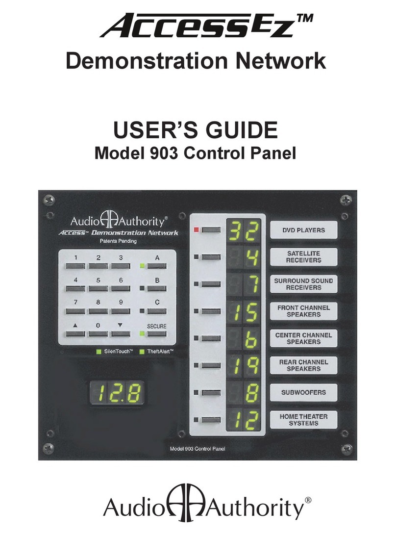
Audio Authority 902 User manual

USER’S GUIDE
Model 902/903 Control Panel
Demonstration Network
2048 Mercer Road, Lexington, Kentucky 40511-1071
Phone: 859-233-4599 • Fax: 859-233-4510
Customer Toll-Free USA & Canada: 800-322-8346
Website: http://www.audioauthority.com
752-288
5/00
å

1
User’s Guide
Table of Contents
Introduction ....................................................................................................................................... 2
Configuring the Control Panel ....................................................................................................... 3
Connecting the Control Panel to the Access™ System ................................................................. 5
Definitions of Special Terms ............................................................................................................ 5
Starting the System the irst Time ................................................................................................. 6
How Product Groups Appear on the Control Panel ................................................................... 7
Selecting Products............................................................................................................................. 8
Storing and Demonstrating Component Systems ....................................................................... 9
Equal Volume Product Comparisons (902 only) ........................................................................ 10
Audio Muting (902 only) ................................................................................................................11
SPL Meter Display (902 only)........................................................................................................ 12
About Secure features .................................................................................................................... 12
Using the Secure eatures ............................................................................................................. 13
SECURE 0 – Display Sleep Mode ........................................................................................... 13
SECURE 1 – System Lockout .................................................................................................. 13
SECURE 2 – Product Group Lockout .................................................................................... 14
SECURE 3 – SPL AutoLimiting (902 only) ............................................................................ 14
SECURE 5 – TheftAlert Alarm Reset ..................................................................................... 15
SECURE 87 – TheftAlert Alarm Memory Display & Clear ................................................ 15
SECURE 88 – System Hardware Reset .................................................................................. 15
SECURE 89 – Display Software Revision Number .............................................................. 15
SECURE 91 – Global On/Off for Secure Commands .......................................................... 15
SECURE 92 – Specify a Default System Selection ................................................................ 16
SECURE 93 – Set SPL AutoLimiting Threshold (902 only)................................................. 16
SECURE 94 – EVC AutoCalibration Master On/Off (902 only) ........................................ 16
SECURE 95 – TheftAlert Master On/Off .............................................................................. 17
SECURE 96 – Systems Write Protection eature On or Off ................................................ 17
SECURE 97 – Set System Write Protect Status for Current Selection ................................ 17
SECURE 98 – Specify a Range of Systems to Write Protect ................................................ 18
Using Product Selector Buttons .................................................................................................... 18
Using the 905 Remote Control ...................................................................................................... 18
Troubleshooting .............................................................................................................................. 19
Index ................................................................................................................................................. 20
The Access™ Demonstration Network is protected by U.S. Patent numbers 5,422,631 and 5,646,602 with other patents
pending.
Access, Audio Authority, the double-A symbol, SilenTouch, AutoLimiting and TheftAlert are trademarks of Audio
Authority Corporation. The software imbedded within the Access™ System is not sold, but rather licensed for this
product specific use. The original purchaser is licensed to use this software in this product and this application only.
Under this license, the software may not be reproduced, copied, disassembled, distributed by any means, licensed, rented,
sold, or in any way revealed to or used by a third party.
ProLogic™, Dolby Digital™, and AC-3™, are Trademarks of Dolby Laboratories.
Model 902 and 903 Control Panel or Access™ Systems

2
Introduction
The Model 902 and 903 Control Panels connect to the Access™ Demonstration Network switching system to
show the products currently selected to play and to provide an easy method of controlling the display to
select products, store and recall systems, and activate special features. The panel controls are divided into
three functional sections - a selection keypad, a Product Group selection area and (902 only) an Equal Volume
Comparison (EVC) section. See the illustration below.
Product Group (PG) Section
RECEIVER
FRONT SPEAKERS
CENTER
SPEAKER
SURROUND
SPEAKERS
ATTEN.
LEVEL
(STORE)
EQUAL VOLUME COMPARISON
ATTENUATION / SPL
DECIBELS
MUTE
(ADJUST) P-NOISE AUTO-CAL
TheftAlertSilenTouch
™
123
456
789
0
A
B
C
SECURE
ON / SPL
SUBWOOFER
LASERDISC
VCR
SYSTEMS
ASD
å Demonstration Network
Patents Pending
Model 902 Control Panel
The Selection Keypad includes:
- 0 – 9 numeric keypad
- UP and DOWN arrow keys for scrolling through selections
- A/B/C comparison keys for easy system comparison
- SECURE key for accessing various secure modes and system features
- SilenTouch™ circuit indicator
- Theft Alert™ indicator
- infrared remote receiver window
The Product Group Section includes the following for each of the 8 Product Groups:
- a Select key for activating each Product Group
- an LED indicator that illuminates when each Product Group is Selected
- a 2-digit display that shows the number of the ACTIVE component
- an ID window for slide-in Product Group labels
The Equal Volume Comparison (EVC) section includes:
- 902 and 903: 3-character display window for displaying command prompts, diagnostic information and
software version number
or 902 only:
- 3-character window also displays volume, attenuation, and muting levels
- keys to activate, adjust, calibrate and store EVC settings
- keys to activate and adjust two levels of audio muting
- a key to change the window’s display function from EVC/Mute Level to a real time
Sound Pressure Level (SPL) display
Indicator Select Key Product Group Display Window Label Insert
Selection
Keypad
Equal Volume
Comparison
(EVC) Section
(902 only)
EVC Display
Window
(902 and 903)

3
In addition to the 902 or 903 Control Panel, the Access™ System can also be operated by:
• Product Select Buttons - push-button located next to each product
• Model 905 Remote Control - a small, inexpensive, full-function remote (included with the 902 and
optional for the 903)
• Compatible PC/Modem - system input/output via the control panel’s RS-232 serial port.
One unique characteristic of the Access System is that all of these different modes of product selection may be
used in the same system. This means that your system could contain a Control Panel, an IR Remote, and
Product Select Buttons, as well as an external computer or modem hooked to the Control Panel’s RS-232 port.
So, it is important for you to be familiar with your system and know the different modes of access (input) to
your system.
Product Group Expansion Port
34-Pin connector for Model 904
ProductGroup Expander
Configuration DIP Switches
to enable/disable control panel
features
3-Pin Header
connection for Model 990
Auxiliary Infrared Receiver
10-Pin Header
connection for Model
987 Audio Level Module
(902 only)
6-Pin Header
connection for Model 980
System Module
RS-232 Serial Port
Modular Jack for connecting
a PC or modem
Microphone Jack
Connect 902 microphone
extension cable here
Model 902/903 Control Panel - Rear View
(for simplicity, only larger component parts are depicted)
AUX IR
MICROPHONE
TO 904
ON
A
B
C
D
E
F
G
H
RS-232
Configuring the Control Panel
On the back of the Control Panel is a bank of Configuration DIP Switches that enable or disable certain
functions. These switch settings should have been adjusted to match your merchandising requirements
during the installation, however, they may be changed at any time. The following chart details the function
of each switch.

4
Factory
Switch Function Setting Comment
A Key Click O Provides audible feedback of key presses (beep)
B Demo Mode O Turn ON only when control panel is not connected to a
system as a “Training Mode”
C Systems Product Group ON ON makes the last unused Product Group capable of
storing and recalling 99 system configurations
D Not Currently Used O
E Previous Selection Key O O = “C” key is the third “flash memory” key
ON = “C” key is toggle between current selection and previous
selection
903 Mode ON This switch must be O for the Model 902 and ON for the 903
G Internal IR Receiver ON Turn ON if using Model 905 remote control
H Auxiliary IR Port O Turn ON if using 990 auxiliary infrared remote receiver.
Switch-C is of particular interest for most retailers. Turning Switch-C to ON allows the last Product Group
position on the Control Panel to be used for storing and recalling up to 99 different component systems. If the
system includes 904 Product Group Expanders, the Systems Product Group will be the last position, on the
last 904. When this feature is enabled, the Systems Product Group will display dashes (– –) or a System
number in its window.
or those whose merchandising emphasizes direct A/B type product comparisons, Switch-E offers an inter-
esting option. Turning Switch-E to ON will change the function of the C-Key from a temporary system
storage key, to an A/B key that reverts to the previous selection whenever it is pressed. This allows for a
simple, one-button A/B capability without having to “store” anything. This feature is especially useful when
your demo includes putting the remote control in the customer’s hand and letting him/her switch at will,
using just one button.
If your installation includes the Model 990 Ceiling-Mounted Infrared Receiver, then Switch-H must be
enabled for that device to operate. If there is no remote control in your system, you should turn Switch-G
O , to eliminate any possibility of stray infrared signals or other “noise” from affecting the display.
The configuration DIP switches are read by the Control Panel each time it is reset or powered up. Therefore,
for any changes to the configuration DIP switches to become effective, the Control Panel must be reset (see
Secure eatures section, Secure 88) or powered down and restarted for the changes to be recognized.

5
980
987 902
Connecting the 902 or 903 to the Access™System
Control panels connect to the Access System via the Model 980 System Module (See Hookup Diagram below).
They also have terminals for the connection of an auxiliary ceiling-mounted Omnidirectional Infrared Re-
ceiver, which extends the range of the remote control’s operation.
Definitions of Special Terms
To best understand and use this powerful merchandising tool, it will be helpful to clarify a few terms used
throughout this manual.
COMPONENT The merchandise or products connected to the switching system.
SWITCH MODULE Small, intelligent, circuit board assembly that provides the actual switching for 4
to 8 components in the system. All components are connected to switch modules,
which in turn selectively interconnect products for demonstration. Your system
may contain several types of switch modules – Low-Level modules for sources or
amplifier inputs, High-Level modules for amplifier outputs, Speaker modules,
Video modules, and so forth. The quantities and types of modules contained in
your system depend on the number and types of components in your display.
SYSTEM BUS A set of wires which interconnect all switch modules allowing control signals
(instructions) to flow between them. The system bus is color-coded, using red/
yellow/black/blue wires and operates as an RS-485 serial interface.
ADDRESS Like your street address, a unique logical numeric code assigned to each module
to differentiate it from all others and enable reliable delivery of instructions via
the System Bus. Each module in the display can “talk” to and receive instructions
from the Control Panel, Product Select Buttons, the 905 IR Remote, a local PC, or a
PC via modem.
Product Group A group of functionally similar components within the display, such as
or GROUP CD players, amplifiers, front speakers, subwoofers, VCRs, etc. The 902 Control
Panel has provisions for 8 Product Groups and has capacity for 99 components in
each Product Group. The number of Product Groups can be expanded by adding
a 904 Product Group Expander. Each 904 Expander adds 8 more Product Groups
to the system, each capable of 99 components. You can add three 904s making the
Access System’s total capacity 16 electronic Product Groups and 16 speaker
Product Groups, each capable of handling 99 products, for a total of 3,168 prod-
ucts in a system.
Model 902 Hookup Diagram
Mic Input
(902 only)
Model 990 Ceiling
Mount Infrared
Receiver
To Amps/Receivers
Input to 987
EVC Audio
Level Module
(902 only)
Output of Source Bus
Auxilliary Infrared
Receiver Input
10-conductor Cable to
987 Module (902 only)
6-conductor Cable to
980 System Module

6
SELECTED The Product Group currently selected to be the object of keypad input.
PRODUCT GROUP A Product Group is selected by pressing its Select Key and confirmed by the
illumination of its red LED Indicator. When “selected,” input from the numeric
keypad will be displayed in the selected Product Group’s 2-digit window and
directed to its switch modules.
ACTIVE Any Component or Product Group that is currently selected to play, i.e. part of the
signal path. The 2-digit number for all active components is shown in its respec-
tive Product Group window.
PRESS A momentary press and release of a key . The PRESS is used for primary key
functions like entering numbers or selecting a Product Group.
DOUBLE-CLICK To press and release a key twice in rapid succession. Used for alternate key
functions, such as turning off an active Product Group.
LPRESS To press and hold a key until the Control Panel beeps (about 1/2 second) then
release. LPRESS is generally used to store values. Examples are defining systems
and storing current selections using A/B/C keys, etc.
HOLD To HOLD a key down while PRESSing other keys, like the “Shift” key on a
computer keyboard.
TIMEOUT The automatic termination of an incomplete keypad or remote control command
after a set amount of time; the control panel is restored to its previous state.
Starting the System the First Time
Once installed, the Access™ System should be tested prior to connecting components to the switching mod-
ules. A self-test routine is automatically initiated when you first power-up the system. When the system is
powered up, you should observe the following sequence of events in the system.
A. 902/903 Test Sequence. If you encounter any problems, keep a note pad handy to record results as they
are reported in the Control Panel windows.
1. All display segments and indicators on the control panel are lit briefly (lamp test).
2. The EVC window at the left of the panel displays software version (e.g., 3.4).
3. A System Bus Test is performed. If the word “bUS” flashes in the EVC window, it indicates a
problem with a system bus cable or switching module. To find the faulty cable or module, use this
process of elimination:
• Carefully unplug the yellow-red-blue-black system bus cable from a switch module to
isolate it from the 980 module, then press any key on the control panel.
• If “bUS” still appears on the EVC window, plug the cable back in and try a different
module.
• If “bUS” disappears from the EVC window, you have isolated the module or section of
bus cable that is faulty. Call Audio Authority® Technical Service at 800-322-8346 for
assistance with parts replacement.
4. After the bus test, the diagnostic program scans the active range of module addresses in every
Product Group. You will observe these module addresses counting up in the EVC window as the
product group number is displayed in each group’s Product Group window.
• If the numeric displays begin flashing at any time during the module scan, two or more
modules have the same address. Duplicate addresses are disallowed because the control
panel is unable to tell two identically addressed modules apart. Note the last group

7
number displayed in the Product Group windows and the module number displayed in
the EVC window and try to find two modules that both have this address. or example, if
the control panel is flashing, the EVC window displays 002, and the third Product Group
window shows S4, you would look for two speaker modules (932) with the same address
of “Group 4, Module 02, Right.” Remember that pairs of speaker modules must have the
same Group and Module ID address, but must be identified LE T and RIGHT to avoid a
duplication.
Note: In Control Panels, “E” refers to Electronics switching modules and “S” refers to Speaker
switching modules.
• As each new group number appears in a Product Group window, the EVC window counts
up the number of modules in that group that can be recognized. Write down the highest
number reported in the EVC window and the Group number with it. or each group,
compare the reported module tally with a physical count of the modules. or example,
your system has four “E Group 0” modules, six “E Group 4” modules, and three pairs of
“S Group 4” modules. The top PG window displays “E0” as EVC scans up to 4 (good).
The second PG window displays “E4” as EVC scans up to 5 (bad). The third PG window
displays “S4” as EVC scans up to 3 (good). In this case you would look for a mis-ad-
dressed, unplugged, or faulty E4 module (Electronics Group 4).
• If the module count in a group does not match the number of modules you actually have,
look for disconnected or mis-addressed modules.
B) After the diagnostic routine, the Control Panel software version number will be displayed, and the Control
Panel will BEEP to indicate that it is ready for use.
At this point the Control Panel should display “– –” or numbers in the window of each valid Product Group.
If this exact sequence of events does not occur, there is a problem with the installation. Do not proceed with
connecting product to the system until the all installation problems have been resolved. If you need assis-
tance, call our Technical Service Department toll-free at 800/322-8346.
When the system is turned on each time hereafter, the selection last made, or a default system that has been
programmed will appear in the Product Group windows.
How Product Groups Appear on the Control Panel
Module addresses set during installation determine the order in which Product Groups appear on the Control
Panel. If the rules for addressing described in the Installation Manual are followed, the first (top) Product
Group should be Sources, with the next logical component Product Group in the signal path being the second
Product Group (e.g. amplifiers, or maybe preamp EQs or processors). Here are two examples of how Product
Groups might be configured on your Control Panel:
Product Group Window Home Audio Display Car Audio Display
1 A/V Sources Head Units
2 Surround Receivers Preamp EQs
3 ront Speakers ront Amps
4 Center Channel Speakers Rear Amps
5 Rear Speakers ront Speakers
6 Subwoofers Rear Speakers
7 – – Sub Amps
8 Systems (up to 99) Subwoofers
Notice that the Product Groups are in a logical order that represents the normal signal flow of the compo-
nents if they were “hard-wired.” Notice also that speaker Product Groups follow their related amplifier’s
Product Group. Your particular demonstration needs may not require that all Product Groups be used,

8
leaving some vacant (i.e. no attached switching modules). If this is the case, then your 902/903 Control Panel
can be used very creatively by programming a single promotional system into each unused Product Group,
for instant one-button activation. Such a configuration might use Product Groups 4 - 7 like this:
Product Group Window Audio Video System
1 Sources
2 Receivers
3 Speakers
4 Manager’s Special
5 $649 Installed!
6 The Latest Technology
7 Advertised Special $499
8 Systems
The last Product Group can store up to 99 preprogrammed systems of your choice if there are no components
assigned to that Product Group. To enable this feature, DIP Switch “C” on the Control Panel’s Configuration
DIP Switch array must be ON. See the diagram on page 3.
Blank and printed labels for all types of component Product Groups are included with your 902 or 903
Control Panel. However, you may wish to make your own labels using different words, symbols or lan-
guages, maybe even on different colored paper. If so, custom label inserts can be printed on 20 - 24# paper
using the following specifications:
Label size: .45” H x 2” W Max. Text Width: 1-3/8”
Text Center: 11/16” from left edge Max. Text Height: 3/8”
Selecting Products
To select a product from the Control Panel by the product number:
1. PRESS the desired Product Group Select Key if that group is not already Selected.
2. Enter a 1 or 2 digit product number using the numeric keypad (the Product Group display clears
and then flashes the new entry).
3. PRESS the Product Group Select Key to enter your new selection.
You may also simply wait 2 seconds and the new selection will be entered automatically without PRESSing
the SELECTED Product Group key. Any component in any Product Group can be SELECTED in this manner
(Auto-Enter).
To play multiple pairs of speakers in the same Product Group:
1. Make sure the desired speaker Product Group is SELECTED (LED ON).
2. Enter 1 or 2 digit number of speaker pair you wish to add and LPRESS Product Group key.
The SELECTED speaker’s Product Group window will alternately display the two speaker pair numbers.
You may add more speaker pairs in the same manner (depending on system limitations set during installa-
tion), but remember that you could be presenting a severe load (low impedance) to the amp’s output, so be
careful. Check the receiver or amplifier manufacturer’s recommendations for maximum number of speakers.
To deselect one of the speaker pairs playing in the same Product Group:
1. Enter the 1 or 2 digit number of the pair you wish to deselect, and
2. PRESS the corresponding Product Group key or simply wait for Auto-Enter.
Note: The maximum number of speakers that can play at the same time is determined by DIP Switch
settings on the 980 System Module Board. If you cannot select multiple speakers to play simultaneously,
please refer to the Installation Manual’s instructions on setting the 980 System Module or call the factory at
800-322-8346.

9
To select a product from the Control Panel using the UP/DOWN arrow keys:
1. PRESS the desired Product Group button if not already SELECTED.
2. Use the UP key (▲) to select next higher numbered product in Product Group and press repeat-
edly to continue advancing.
3. Use the DOWN key (▼) to select next lower number product in currently SELECTED Product
Group.
DOUBLE-CLICK of the UP/DOWN keys will increment/decrement product selection by a factor of 10. If
UP/DOWN arrow keys are used to scroll through a speaker Product Group where multiple pairs of speakers
are ACTIVE, then the most recent speaker selection is incremented or decremented. The other ACTIVE
speakers in the Product Group are not affected.
To turn off all products in a Product Group:
This may be done by either of two ways:
1) Deselect the Product Group by DOUBLE-CLICKing its Select Key, or
2) Deselect the ACTIVE product within that GROUP by entering its number again.
In both cases the result is the same. The Product Group window will display dashes (– –), indicating that the
Group is available, but not ACTIVE.
Storing and Demonstrating Component Systems
There are three different ways to store complete systems with 902 or 903 Control Panels. During product
demonstrations, it is normal to “build” a system for your customer as you qualify his/her needs during the
selling process. Once the components of the desired system are active, the system may be stored in one of the
following ways:
1) LPRESS the A, B, or C keys. These keys are essentially used like scratchpad or “flash” memory.
Once a system has been stored in this way, PRESS A, B, or C to instantly compare the stored
systems. uture systems can be stored in A, B, or C by repeating the same process thereby over-
writing the previously stored systems.
2) LPRESS any unused Product Group Select Key to store the system that is currently playing. Once
stored, the system can be SELECTED by simply PRESSing the Product Group key. When selected,
“SY” will be displayed in the system’s Product Group window and all the components comprising
the system will have their numbers displayed in their respective Product Group windows. uture
systems can be stored in the same manner by simply overwriting with a newly selected system.
3) Store as 1 of up to 99 systems in the Systems Product Group. To do this:
• Select the Systems Product Group by PRESSing its Select Key.
(DIP Switch-C must be ON).
• Enter a 1 or 2 digit number (e.g. #22) for the system.
• LPRESS the Systems Product Group’s Select Key to store.
Continue this procedure to store up to 99 systems. Systems that have been temporarily stored using the A, B,
or C keys may be copied to the System Product Group to prevent being erased.
To select a system previously stored in the System Product Group:
1) SELECT the Systems Product Group,
2) Enter the 1 or 2 digit system number you wish to play, and
3) PRESS the Systems Product Group key or wait 2 seconds for auto-enter.
You may also use the UP/DOWN arrow keys to scroll through systems.

10
Equal Volume Comparisons (902 Only)
The Equal Volume Comparison, or EVC Section of the Control Panel, provides a variety of advanced features
to enhance your demonstration capabilities. Generally, these features are:
1) Automatically adjusting for equal volume levels among speakers when performing A/B-type
comparisons.
2) 2 levels of audio Muting to instantly lower the demo volume by a preset amount when you need
to talk over the music.
3) Digitally display in decibels the current Sound Pressure Level (SPL) in the demo area.
The concept and need for equal volume product comparisons is based on two facts. irst, a limitation of
human hearing is that our sensitivity to low, middle, and high frequency sounds varies with the volume level.
As the volume level decreases, our sensitivity to low and high pitched sound becomes progressively worse.
Conversely, as the volume, or SPL, increases our hearing steadily improves to provide a more even response
across the full audio spectrum. or this reason, in any A/B-type product comparison, the products being
auditioned must be played at exactly the same loudness to negate this deficiency in our hearing.
The second factor is that audio components vary randomly in their electrical sensitivity, or efficiency – that is,
with the exact same input signal, two different components will likely produce differing amounts of output.
This characteristic is most pronounced in loudspeakers, but is also found in amplifiers. However, a product’s
efficiency is not necessarily a measure of quality or accuracy.
These two factors combined mean that in any A/B-type product comparison it is imperative that the demon-
stration system provide a convenient and accurate method to eliminate any volume differences between the
products being auditioned. Otherwise, the listener will almost always hear the louder product as sounding
better, even when its reproduction quality may actually be inferior. or valid product comparisons, all
products must be playing at exactly the same sound pressure level. That is what EVC is all about.
Despite its importance and benefits, providing equal volume demonstrations in a showroom setting usually
requires additional education, training, time and effort for salespersons. However, with the Model 902, this
critically important aspect of your product presentation can happen automatically! The 902’s EVC Section is
able to sample the relative efficiency of each component within a Product Group and store its relative effi-
ciency. When EVC is ON, selecting a product automatically recalls its relative efficiency, adjusts its loudness,
and allows the 902 to play each product at exactly the same volume level.
Equal volume adjustments are performed by the Model 987 Audio Level Module, which is included with the
902 Control Panel. This 987 Module is inserted in the system’s signal path just prior to the input bus of each
amplifier group (see diagram). Each 987 has 4 channels (two stereo pairs) available. Additional 987 Modules
can be used to adjust more than 4 channels. The 902 also includes a precision calibration microphone (typi-
cally hung from the ceiling) which allows the 902 to measure the SPL in the demo area, and in turn control the
987 Audio Level Module.
EVC can only be applied to corresponding speaker and amplifier Product Groups, that is, electronics and
speaker Product Groups with matching Group numbers. When a valid Product Group is selected, the EVC
window will display two dashes (– –) if EVC is O , or the selected product’s relative efficiency (an attenua-
tion value between 0.0 and 30.0 dB) if EVC is ON.
The EVC section’s control keys and multipurpose display window are associated only with the currently
SELECTED product in the ACTIVE Product Group (the one with its red LED ON). When EVC is ON, that
product’s relative efficiency in decibels is shown in the display. The least efficient product in the Group will
display a value of 0.0 dB, or no attenuation. More efficient products will display the number of decibels of
attenuation necessary to achieve equal volume.

11
To turn the EVC eature ON or O :
1) SELECT a valid Product Group for EVC by PRESSing its Select Key.
Valid Product Groups are typically speakers and amplifiers. EVC cannot be applied to source
Product Groups.
2) PRESS the ON/SPL key in the EVC section of the panel to toggle between ON and O .
To automatically calibrate products for equal volume:
1) Verify that EVC is ON.
2) SELECT a valid Product Group to calibrate.
3) Adjust volume to moderately loud listening level.
4) LPRESS the AUTO-CAL key.
This will activate the 902’s pink noise generator and initiate the automatic calibration sequence. Each product
in the group will be selected in turn and its relative SPL measured by the 902’s microphone. The 902 will
calculate each product’s relative efficiency and automatically store that value in memory (overwriting any
previously stored value) as a default for whenever that product is selected.
To manually adjust attenuation values:
1) Verify that EVC is ON.
2) SELECT a valid Product Group to manually adjust.
3) Adjust volume to moderately loud listening level.
4) PRESS the P-NOISE key to activate the pink noise source, or use music.
5) Use the ATTEN. LEVEL UP (▲) or DOWN (▼) arrow keys to increase or decrease the attenuation
value.
PRESS arrow keys to increment 0.2 dB.
DOUBLE-CLICK arrow keys to increment 10dB.
HOLD arrow keys to increment at a steadily increasing rate.
6) To store a new attenuation value for the currently SELECTED product in the ACTIVE Group,
LPRESS the ON/SPL (STORE) key until it beeps.
NOTE: Manual adjustments which are not saved (Step 6) as the new default, will not be retained for later use.
7) Repeat Step 5/6 for each product you want to adjust.
8) Turn off Pink Noise Source by PRESSing the P-NOISE key, or PRESS the ON/SPL key to turn EVC
feature O .
Audio Muting (902 Only)
The 902’s EVC section also provides two programmable levels of audio Muting. Muting enables the operator
to immediately lower the audio level by a predetermined amount during demonstrations to allow conversa-
tion with the customer without having to yell over the music. It is also convenient for situations like answer-
ing the phone in the demo area, or regaining control when self-serve customers get too loud. Muting can also
be used as a “safety” feature to protect from unexpected volume blasts when selecting high powered amplifi-
ers.
Whenever audio Muting is engaged, the amount of muting attenuation will flash in the EVC display window.
The factory default settings are:
20dB of attenuation for Muting Level 1, and
30dB of attenuation for Muting Level 2.
To activate Muting Level 1:
PRESS the MUTE Key.

12
To activate Muting Level 2:
DOUBLE-CLICK the MUTE Key.
To change the amount of Muting attenuation:
1) HOLD the MUTE Key while using the ATTEN. LEVEL up (▲) or down (▼) arrow keys to adjust.
2) RELEASE the MUTE Key when the desired muting level is displayed.
The displayed value will become the new default attenuation for the currently engaged Muting Level. Level
1 and Level 2 attenuation are independently adjustable.
To turn off Muting (or revert Muting Level 2 back to Muting Level 1)
PRESS the MUTE Key.
SPL Meter Display (902 Only)
Using its EVC microphone, the 902 Control Panel can digitally display in decibels the Sound Pressure Level
(SPL) in the demonstration area, up to 100 decibels. SPL values being displayed can be distinguished from
EVC or Muting attenuation levels because they contain no decimal point.
The 902 can also monitor the demo area and automatically engage Muting Level 2 whenever the SPL exceeds
a predetermined level (See Secure eature 93 for more information).
To toggle the Sound Pressure Level display ON/O
DOUBLE-CLICK the ON/SPL Key.
About Secure Features
Beyond the basic operational features are many special features and functions that can dramatically enhance
the switching system’s convenience and utility. Secure eatures allow you to control and restrict access to the
display, put the switching system into the SLEEP mode, protect stored systems from accidental erasure, etc.
These special features are initiated with the SECURE Key. Properly used, Secure eatures will eliminate most
of the risks associated with giving customers access to the switching system, making offensive “Please Don’t
Touch” signs unnecessary. The Access System is designed to be equally appropriate for operation by you or
your customer.
Control over these special features is by two different SECURITY CODES – a MANAGER CODE and an
OPERATOR CODE. Whenever a Code is required to execute a Secure eature, “coA” will appear in the
display window to prompt for the Manager Code, or “coB” to prompt or the Operator Code. Security Codes
can be any number from 0 to 999. Or, either Code may be set to null or empty, to bypass the requirement of
entering a Code altogether. The Manager’s Code is used to control access to certain system setup param-
eters, while the Operator Code is used to restrict Customer access. The MANAGER CODE, or Code A, is
factory set at 999. The OPERATOR CODE, or Code B, is factory set as blank or null.
Changing the Manger’s Code requires you to press and hold the recessed
button on the Control Panel. To reach the button, you must unbend a paper
clip and insert it through the hole in the Control Panel as shown. While
holding the recessed button, short press the A key. The Manager’s Code
will appear. To change the code, press the C key to backspace, and then
enter a new three digit code and long-press the A key to enter. Release the
recessed button to exit Change Password Mode. Changing the Operator’s
Code is a similar process: while holding the recessed button, short press
the B key. The Operator’s Code will appear. To change the code, press the
C key to backspace, and then enter a new three digit code. Long-press the
B key to enter. Release the recessed button to exit Change Password Mode.
FRONT SPEAKERS
CENTER & REAR
SPEAKERS
SYSTEM
OF THE WEEK
SYSTEM
OF THE MONTH
ASD
TheftAlertSilenTouch
å Demonstration Network
Patents Pending
123
456
789
0
A
B
C
SECURE
MANAGER'S
SPECIAL
SOURCES
RECEIVERS
SYSTEMS
TM
Recessed button used to activate
Change Password Mode.

13
All Secure Commands are initiated by PRESSing the SECURE Key, followed by the number of the desired
feature or function. During Secure Command key sequences, the SECURE Key is used like an “Enter” key to
confirm input and move to the next operator prompt. Also, the Arrow Keys, depicted as ▲ for UP and ▼ for
DOWN, are used to toggle between available choices. When one Secure Command has an impact on, or is
dependent on another, that is also noted. The Manager Code may be substituted at any prompt for the
Operator Code. Of course, the opposite is not true.
Most secure functions have a TIMEOUT function that automatically terminates the command in process and
puts you back where you were previously if the keystrokes are not entered properly or if you take too long.
So if you are interrupted in the middle of entering a Secure Command, you need not worry about the system
being inadvertently left vulnerable. It may take a little practice for the Secure eatures to become second
nature. After all, this aspect of the Control Panel’s operation is security related and should not be too obvi-
ous.
TIP: If you experience any initial uncertainty in entering any Secure Command, DOUBLE-CLICKing the
SECURE Key will terminate the current command sequence and return the Control Panel to its previous state,
allowing you to start over.
The different Secure Commands are listed in the following section along with an explanation of what each
code does.
Using the Secure Features
Please acquaint yourself with the Secure 91 and Secure 95 Codes first, since they are generally required for
other Secure eatures to operate. Generally, those Secure eatures that are used frequently and by store
personnel have lower numbers to reduce keystrokes. Secure eatures requiring the Manager Code to make
changes generally have higher numbers.
In this section, the keys to press are capitalized. Keystrokes are separated by a dot (•). The entry of numbers
is indicated by the # sign, one for each possible digit. An asterisk (*) indicates that a keystroke is optional,
that is, it will automatically execute if the key is not pressed.
SECURE 0 – Display Sleep Mode
The Sleep Mode provides the equivalent of a master on/off switch for the display system. When in sleep
mode, the switching system is still powered but all products are deselected, all lights on the Control Panel are
off (except for a single flashing LED “pulse”), 12-volt ignition power to car audio products is turned off, and
all operator input is ignored, except to awaken the system.
- Secure 91 must be ON to use this feature.
- POWER switch on the 980 System Module must be in the O position.
To Initiate Sleep Mode (turn system O ):
1) SECURE • 0 • SECURE*
To Awaken (turn system ON):
1) Press any key.
If no Operator Code is defined the system will awaken immediately.
Otherwise, you will be prompted for Code B (coB). Proceed to Step 2 below.
2) # • # • # • SECURE*
SECURE 1 – System Lockout
Causes the system to ignore all operator input from the Control Panel, Product Select Buttons, or 905 Remote.
This is very useful to prevent unwanted system tampering.
- Secure 91 must be ON to use this feature.

14
To Lockout or Unlock System, PRESS:
1) SECURE • 1 • SECURE*
2) ▲ or ▼ toggles between 'ON' (locked out) & 'O ' (unlocked)
3) SECURE*
“LO” appears in 3 character window when system is locked out.
If 'coB' appears in 3 character display window, enter 3-digit Code A or Code B, described in
Step 4.
4) # • # • # • SECURE*
SECURE 2 – Product Group Lockout
Deselects all products in the affected Product Group and prevents any product in the group from being
selected. Multiple Product Groups may be locked out one Product Group at a time.
- Secure 91 must be on to use this feature
To Lockout a Product Group:
1) Press Select Key of Product Group to Lockout
2) SECURE • 2 • SECURE*
“LO” appears in selected Product Group window.
To Unlock a Product Group:
1) Select locked Product Group by pressing its key, then PRESS
2) SECURE • 2 • SECURE*
If “coB” appears in 3 character display window, enter 3-digit Code A or Code B, described in
Step 3.
3) # • # • # • SECURE*
SECURE 3 – SPL AutoLimiting (902 Only)
This feature uses the 902’s EVC microphone to monitor the Sound Pressure Level (SPL) in the demo area. If
the SPL reaches a preset limit (set by Manager with SECURE 93), the Control Panel will automatically engage
Muting Level 2 to reduce the SPL below the allowable threshold.
- Secure 91 must be on to use this feature
To Engage or Disengage SPL AutoLimiting eature, PRESS:
1) SECURE • 3 • SECURE*
2) ▲ or ▼ toggles between ON (AutoLimiting Engaged) & O (AutoLimiting Disengaged)
3) SECURE*
If 'coB' appears in 3 character display window, enter 3-digit Code A or Code B, described in
Step 4.
4) # • # • # • SECURE*
LED beside the SECURE Key will remain ON when this feature is engaged.

15
SECURE 5 – TheftAlert Alarm Reset
Shuts off alarm or siren after TheftAlert detects that a product has been removed without permission, and
resets TheftAlert to detect another theft.
- Secure 91 & Secure 95 must be on to use this feature.
- TheftAlert switch on the 980 system module must be in the O position.
To turn off Alarm, PRESS:
1) SECURE • 5 • SECURE*
SECURE 87 – TheftAlert Alarm Memory Display & Clear
Displays from memory the product numbers of any components that have triggered a TheftAlert
alarm, and allows memory contents to be cleared after being displayed.
- Secure 91 & Secure 95 must be on to use this feature.
To display or clear a Theft Alert alarm, PRESS:
1) SECURE • 8 • 7 • SECURE*
If desired, press SECURE to end flashing displays before 30 second timeout.
2) LPress SECURE to clear TheftAlert memory.
If “coA” appears in 3 character display window, enter 3-digit Code A or Code B, described in
Step 3.
3) # • # • # • SECURE*
SECURE 88 – System Hardware Reset
Provides a method for forcing a hardware reset (warm boot) for the control panel, switch modules, and 980
system module. Used after changing switching module address, control panel DIP switch settings, etc. to
store new values, as a convenient alternative to removing power from the system.
To reset system, PRESS:
1) SECURE • 8 • 8 • SECURE*
SECURE 89 – Display Software Revision Number
Causes software revision number to be displayed in the 3 character window for 2 seconds.
To display software revision number, PRESS:
1) SECURE • 8 • 9 • SECURE*
SECURE 91 – Global On/Off for Secure Commands
Provides a master on/off toggle for most secure features.
To turn Secure features ON/O , PRESS:
1) SECURE • 9 • 1 • SECURE*
2) Use the ▲ or ▼ keys to toggle between “ON” (features enabled) & “O ” (features disabled)
3) SECURE*
If “coA” appears in 3 character display window, enter 3-digit Code A in Step 4.
4) # • # • # • SECURE*

16
SECURE 92 – Specify a Default System Selection
When on, provides the capability for the control panel to automatically activate a 'default' system after a
specified period of input inactivity at the Control Panel or Product Selector Buttons.
- Secure 91 must be on to use this feature.
To Specify a Default System Selection or Turn eature O :
1) Select desired system on Control Panel, then PRESS:
2) SECURE • 9 • 2 • SECURE*
3) “O ” (feature disabled) or “##” (feature ON) minutes will be shown.
4) Press ▲ or ▼ Keys to set the number of minutes of inactivity to activate the default system.
PRESSing ▼ until “O ” appears in 3 character window turns feature off.
5) SECURE*
If “coA” appears in 3 character display window, enter 3-digit Code A in Step 6.
6) # • # • # • SECURE*
SECURE 93 – Set SPL AutoLimiting Threshold (902 Only)
Allows the Manager to change the value for the maximum Sound Pressure Level (SPL) threshold, used for
Secure eature #3 “SPL AutoLimiting.” The default value from the factory is 85dB.
- Secure 91 must be on to use this feature.
To change the SPL AutoLimiting Threshold, PRESS:
1) SECURE • 9 • 3 • SECURE*
“##” appears in prompt window to indicate current SPL value.
2) Enter desired value with numeric keypad.
3) SECURE*
If “coA” appears in 3 character display window, enter 3-digit Code A in Step 4.
4) # • # • # • SECURE*
SECURE 94 – EVC AutoCalibration Master On/Off (902 Only)
Allows the EVC AutoCalibration feature to be disabled. This may be desirable when management does not
want AutoCal run indiscriminately, or wants to prevent custom EVC attenuation settings from being auto-
matically overwritten by AutoCal.
- Secure 91 must be on to use this feature.
To Turn the AutoCal feature On or Off, PRESS:
1) SECURE • 9 • 4 • SECURE*
2) Use the ▲ or ▼ keys to toggle between “ON” (AutoCal enabled) & “O ” (AutoCal disabled).
3) SECURE*
If “coA” appears in 3 character display window, enter 3-digit Code A in Step 4.
4) # • # • # • SECURE*

17
SECURE 95 – TheftAlert Master ON/OFF
Allows the TheftAlert Merchandise Sentinel feature to be turned on or off. Also useful if the display contains
products that trigger false alarms.
- Secure 91 must be on to use this feature.
To Turn TheftAlert On or Off, PRESS:
1) SECURE • 9 • 5 • SECURE*
2) Use the ▲ or ▼ keys to toggle between “ON” (TheftAlert enabled) & “O ” (TheftAlert disabled).
3) SECURE*
If “coA” appears in 3 character display window, enter 3-digit Code A in Step 4.
4) # • # • # • SECURE*
SECURE 96 – Systems Write Protection Feature ON or OFF
Write Protection prevents inadvertent or unauthorized changes to management’s stored systems. When the
Systems are Write Protected (this feature ON), over-writing a stored system requires the entry of the Manager
Code (Code A). Given this, if there are several Write Protected systems to change, it is easiest to turn this
feature O temporarily to eliminate the Code A prompt, then turn if back ON, once editing is completed.
- Secure 91 must be on to use this feature.
To Turn Systems Write Protection ON or O , PRESS:
1) SECURE • 9 • 6 • SECURE*
2) Use the ▲ or ▼ keys to toggle between “ON” (Write Protect enabled) & “O ” (Write Protect
disabled).
3) SECURE*
If “coA” appears in 3 character display window, enter 3-digit Code A in Step 4.
4) # • # • # • SECURE*
SECURE 97 – Set System Write Protect Status for Current Selection.
Provides a quick method for setting an individual system's Write Protect status. or setting write protect
status for a range of systems use Secure 98.
- Secure 91 must be on to use this feature.
To Write Protect/Unprotect a Single System, PRESS:
1) SECURE • 9 • 7 • SECURE*
2) Use the ▲ or ▼ keys to toggle between “ON” (Write Protect enabled) & “O ” (Write Protect
disabled).
3) SECURE*
If “coA” appears in 3 character display window, enter 3-digit Code A in Step 4.
4) # • # • # • SECURE*

18
SECURE 98 – Specify a Range of Systems to Write Protect
Allows a range of systems (1-99) to be specified for write protection. The command sequence will prompt
you to specify the Low and High numbers in the range to be protected.
- Secure 91 must be on to use this feature.
To specify a range of systems to Write Protect, PRESS:
1) SECURE • 9 • 8 • SECURE*
“L##” appears in 3 character window.
2) Use the ▲ or ▼ Keys to select the lowest system number in the range.
Use the C-Key as a deleting backspace key if needed.
3) SECURE*
4) Use the ▲ or ▼ Keys to select the highest system number in the range.
5) SECURE*
If “coA” appears in 3 character display window, enter 3-digit Code A in Step 6.
6) # • # • # • SECURE*
Using Product Selector Buttons
Product Selector Buttons offer a very friendly interface that encourages self-service. They also make a power-
ful addition to the merchandising flexibility of systems that use Control Panels. If you have both a Control
Panel and Product Selector Buttons, notice that the Product Selector Buttons communicate with the Control
Panel and vice versa through the bi-directional architecture of your system. Any selection made with a
Product Selector Button will be confirmed by the Product Selector Button’s LED and in the selected
component’s Product Group window on the Control Panel.
Usually, Product Selector Buttons are located adjacent to the component they select. To use a Product Selector
Button, simply PRESS it momentarily. The green LED will light and your selection will play, assuming you
have source material. PRESSing an alternate component’s Product Selector Button will activate the new
selection and deactivate the previous selection. To turn a selected component O , simply PRESS its Product
Selector Button.
One can play multiple pairs of speakers using Product Selector Buttons by adding additional pairs to the
current selection (the maximum number of pairs allowed is determined at installation). To add a pair of
speakers to the current selection, LPRESS the Product Selector Button for the set of speakers you wish to add.
To deselect one of the multiple pairs playing, PRESS its Product Selector Button.
Using the 905 Remote Control
The 905 IR Remote is very easy to use. Every system feature is available from the remote (version 3.4 and
later Control Panels, use Secure 89 to determine your version). To use the 905, point it in the direction of the
Control Panel or Model 990 External IR Receiver and enter your command. The keystrokes and functions
work exactly like the keypad on the Control Panel, except for selecting the active Product Group.
To SELECT a Product Group from the remote numerically, PRESS the GROUP button on the remote, then key-
in the desired Product Group number (1 – 32 starting at the top of the Control Panel), and PRESS the ENTER-
Key.
You can also use the ▲ and ▼ ARROW keys to SELECT a Product Group by PRESSing the GROUP key, then
using the ▲ or ▼ ARROW to move to the desired Product Group.

19
If the last Product Group on your Control Panel is reserved for Systems (see page 3), then PRESS the SYSTEM
key on the remote to go directly to the Systems Product Group.
Once the desired Product Group is active, SELECT the component you wish to demonstrate by entering that
component’s 1 or 2-digit product ID number. PRESS the ENTER-Key on the remote or wait 2 seconds for
auto-entry.
Enhanced features
902/903 Control Panels with version 3.4 software or later include the following functions to the 905 remote.
To store the current selections in an unused product group:
Group • # • # • LPRESS-ENTER
The same sequence applied to a speaker group facilitates speaker add. This sequence be-
haves just like LPRESSing a Product Group button.
To store the current selections in the 99 systems group:
System • # • # • LPRESS-ENTER.
(This function must be enabled on the dip switch, see page 3.) This sequence acts just like LPRESSing
the 99 systems Product Group button.
To disconnect/recall the active product in a group just like a double clicked Product Group button on display:
Group • # • # • DOUBLE CLICK-ENTER
Double click needs to be two moderate presses rather than the speed you would use with a
computer mouse. If you have trouble with double click, slow down and make two distinct
presses.
Group • # • # will time out and act like short press Product Group after 2 seconds on inactivity.
Group • ▲ and Group • ▼ cycles through Product Groups as long as the arrow key is held down.
Troubleshooting
There are two common conditions that can cause a system to malfunction:
1) Switching Modules that are not properly addressed.
2) Buses are improperly connected (system bus, high-level bus, low-level bus).
Either of these conditions can cause the system to be “confused” since the Control Panel cannot then commu-
nicate with all switching modules. All of the module addresses should have been set and all the bus net-
works connected by the person(s) who originally installed your system. If this was not properly done or if
any module addresses have been changed, or new modules added to the system since the original installa-
tion, someone will have to verify all the address settings and check all the bus connections in your system
before further troubleshooting can continue. Run the self-diagnostic tests on page 6 to discover module
addressing problems and refer to the original Installation Manual for instructions on module addresses and
bus connections.
Questions, user input and suggestions are always welcome. Should you have a comment or need help in
using your å Demonstration Network, please call us at 800/322-8346. We’ll be happy to hear from
you. Thank you for your support of our products and services.
Other manuals for 902
1
This manual suits for next models
1
Other Audio Authority Control Panel manuals
Popular Control Panel manuals by other brands
GRASS VALLEY
GRASS VALLEY JUPITER CONTROL PANEL LD4 - datasheet
Trane Technologies
Trane Technologies Tracer TD7 Original instructions
Teletek electronics
Teletek electronics MAG4 user manual
JSB
JSB RS125 user manual

THG PARIS
THG PARIS 6760D installation instructions

ENDA
ENDA EOP4-070 Series installation instructions
