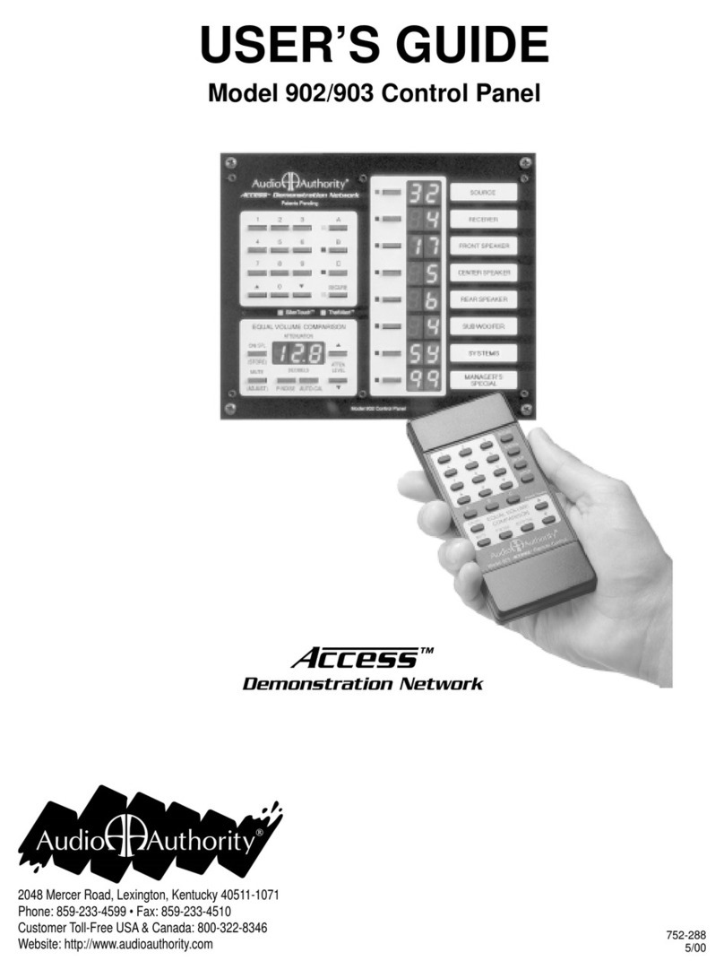
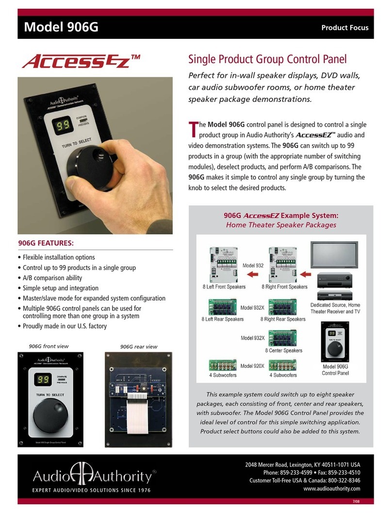
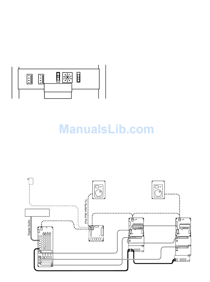
Audio Authority 903 User manual

Demonstration Network
USER’S GUIDE
Model 903 Control Panel

The Access™Demonstration Network is protected by U.S. Patent numbers 5,422,631 and 5,646,602 with foreign patents pending. The software imbedded
within the Access System is not sold, but rather licensed for this product specic use. The original purchaser is licensed to use this software in this product
and this application only. Under this license, the software may not be reproduced, copied, disassembled, distributed by any means, licensed, rented, sold, or
in any way revealed to or used by a third party.
The words “Audio Authority” in any font, the Audio Authority logo, and the “double-A” symbol, are registered trademarks of
Audio Authority Corporation. Access Demonstration Network, AccessEZ, AutoDamping, SPL Auto Limiting, TheftAlert, AccessEZ and SilenTouch are
trademarks of Audio Authority Corporation.
Dolby is a trademark of Dolby Laboratories, Incorporated. HDMI, the HDMI logo and High-Denition Multimedia Interface are trademarks or registered
trademarks of HDMI Licensing LLC. Toslink is a trademark of Toshiba America.
2048 Mercer Road, Lexington, Kentucky 40511-1071
800-322-8346 • 859-233-4599 • Fax: 859-233-4510
www.audioauthority.com • support@audioauthority.com

3
Contents
INTRODUCTION ......................................................................................................................................................... 4
CONFIGURING THE CONTROL PANEL .................................................................................................................... 5
CONNECTING THE CONTROL PANEL TO THE ACCESS™ SYSTEM .................................................................... 6
STARTING THE SYSTEM THE FIRST TIME .............................................................................................................. 6
HOW PRODUCT GROUPS APPEAR ON THE CONTROL PANEL ............................................................................ 7
SELECTING PRODUCTS............................................................................................................................................ 8
STORING AND DEMONSTRATING COMPONENT SYSTEMS ................................................................................. 9
ABOUT SECURE FEATURES .................................................................................................................................. 10
USING THE SECURE FEATURES ........................................................................................................................... 10
SECURE 0 – DISPLAY SLEEP MODE ..................................................................................................................... 11
SECURE 1 – SYSTEM LOCKOUT ........................................................................................................................... 11
SECURE 2 – PRODUCT GROUP LOCKOUT .......................................................................................................... 11
SECURE 88 – SYSTEM HARDWARE RESET ......................................................................................................... 12
SECURE 89 – DISPLAY SOFTWARE REVISION NUMBER .................................................................................... 12
SECURE 91 – GLOBAL ON/OFF FOR SECURE COMMANDS ............................................................................... 12
SECURE 92 – SPECIFY A DEFAULT SYSTEM SELECTION .................................................................................. 12
SECURE 96 – SYSTEMS WRITE PROTECTION FEATURE ON OR OFF .............................................................. 13
SECURE 97 – SET SYSTEM WRITE PROTECT STATUS FOR CURRENT SELECTION ...................................... 13
SECURE 98 – SPECIFY A RANGE OF SYSTEMS TO WRITE PROTECT .............................................................. 13
USING PRODUCT SELECTOR BUTTONS .............................................................................................................. 14
TROUBLESHOOTING .............................................................................................................................................. 14
DEFINITIONS OF TERMS ......................................................................................................................................... 15
WARRANTY ................................................................................................................................................................17
INDEX ........................................................................................................................................................................ 18

4
INTRODUCTION
The Model 903 Control Panels connect to the Access™ Demonstration Network switching
system to show the products currently selected to play and to provide an easy method of
controlling the display to select products, store and recall systems, and activate special
features. The panel controls are divided into two functional sections - a selection keypad and
a Product Group selection. See the illustration below.
Please read and follow these instructions carefully. If you have any difculties during the installation, don’t hesitate
to call us for assistance! We’re open Monday through Friday from 8:30 AM until 5:00 PM, Eastern Time. Also check our
website for diagrams and tips: audioauthority.com/access_tips.
The Selection Keypad includes:
• 0 – 9 numeric keypad
• UP and DOWN arrow keys for scrolling through selections
• A/B/C comparison keys for easy system comparison
• SECURE key for accessing various secure modes and system features
• SilenTouch™ circuit indicator
• Infrared remote receiver window
The Product Group Section includes the following for each of the 8 Product Groups:
• A Select key for activating each Product Group
• A LED indicator that illuminates when each Product Group is Selected
• A 2-digit display that shows the number of the ACTIVE component
• An ID window for slide-in Product Group labels
In addition to the 903 Control Panel, the Access™ System can also be operated by:
• Product Select Buttons - push-button located next to each product
• IR Remote Control - Download IR codes from website
• By using a computer touchscreen with custom software congured to enable product selections
and other control functions
Figure 1. Basic overview of the 903 Control Panel
audioauthority.com/access_tips
• Tips
• Examples
• FAQ
Info Display PG Window
Selection Keypad
Indicator Select Key Product Group Display Window
Label Insert

5
One unique characteristic of the Access System is that all of these different modes of product selection may be used in
the same system. This means that your system could contain a Control Panel, an IR Remote, and Product Select Buttons,
as well as an external computer touchscreen. So, it is important for you to be familiar with your system and know the
different modes of access (input) to your system.
Model 903 Control Panel - Rear View
Conguring the Control Panel
On the back of the Control Panel is a bank of Conguration DIP Switches that enable or disable certain functions. These
switch settings should have been adjusted to match your merchandising requirements during the installation, however,
they may be changed at any time. The following chart details the function of each switch.
Switch Settings
Switch Function Comments
A Keyboard Click Turn ON for audible key feedback or “beep”
B Demo-Mode Leave OFF. Use only when control panel is not
connected to a system as a “Training Mode”
C Systems ON makes the last (unused) Product Group capable of
Memory storing and recalling 99 system congurations*
D Future Use Spare, leave OFF
E Previous Selection OFF = “C” key is third “ash memory” key
ON = “C” key is toggle between current selection and previous selection
F 903 Turn ON
G Internal IR Turn OFF when using Remote IR Receiver
H Auxiliary IR Turn ON when using Remote IR Receiver
Figure 2. Rear view of
the 903 Control Panel.
6-Pin Header
Connection for Model
980EZ System Module
Product Group Expansion Port
34-pin connector for model 904
Product Group Expander Module
Conguration DIP Switches
to enable/disable control panel
features
3-Pin Header
Connection for Auxiliary IR Sensor

6
INSTALLING A CONTROL PANEL
Preparation
A.Cut an opening for the Control Panel if you wish to ush mount it in your
display or other surface.
• For a 903 Control Panel, cut an opening 7” (178 mm) wide by
5-1⁄8” (130 mm) high.
• Use the panel to mark screw hole locations and drill 7⁄64” (2.5
mm) holes for the screws.
• Insert the appropriate slide-in Product Group labels provided with a 903 control panel into the product group
display windows to identify each component group on the panel. Consult page 6 of your 903 User’s Guide for
more information on Product Group labeling.
Note: The 903 Control Panel can also be remotely controlled using a third party IR remote programmed with the IR codes avail-
able at audioauthority.com/access_tips.
B. Using the ten foot cables supplied, plug the 903 into the 980 System Module at the header marked 903 (Figure 3).
C. Set the Conguration Switches on the control panel (See Switch Settings on page 5.)
D. Mount the control panel using the four screws provided. Do not overtighten the screws.
Testing SYSTEM Function
903 Test Sequence
Test the Control Panel. Reboot the system (press Secure, 88, Secure) and
observe the following test results on the Control Panel. If you encounter
any problems, keep a note pad handy to record results as they are
reported in the Control Panel windows.
1. All display segments and indicators on the control panel are lit briey
(lamp test).
2. The Info Display at the left of the panel shows software version
(e.g., 3.4).
3. A System Bus Test is performed.
a. If the word “bUS” ashes in the Info display, it indicates a
problem with a system bus cable or switching module.
b. To nd the faulty cable or module, use this process of
elimination: carefully unplug portions of the yellow-red-blue-black system bus cable to isolate them from the
980 module, then press any key on the control panel. If “bUS” still appears on the Info Display, plug the cable
back in and try a different cable.
c. If “bUS” disappears from the Info Display, you have isolated the module or bus cable that is faulty.
Re-address the module and cycle power or replace the cable.
d. Call Audio Authority®Technical Service at 800-322-8346 for assistance with parts replacement.
4. After the bus test, the diagnostic program scans the active range of module addresses in every Product Group. You
will observe these module addresses counting up in the Info Display as the product group number is displayed in each
group’s Product Group window. Lowest group numbers rst, and electronics groups come up before speaker groups
(e.g., 922, 942, 945, 955, 956, (all electronics), 932, 939, (speakers).
Figure 4.
Info Display PG Window
Figure 3.

7
If the numeric displays begin ashing during the module scan, then two or more modules have the same address.
Duplicate addresses are disallowed because the control panel is unable to tell two identically addressed modules apart
unless they are left and right modules in a stereo pair.
a. Make a note of the last group number displayed in the Product Group windows and the module number
shown in the Info Display nd the two modules that both have this address. For example, if the control panel
is ashing, the Info Display shows 002, and the third Product Group window shows S4, you would look for
two speaker modules (932) with the same address of “Group 4, Module 02, Right.”
b. Remember that pairs of speaker modules must have the same Group and Module ID address, but must be
identied Left and Right to avoid a duplication.
c. If the problem address disappears too quickly to write down, press SECURE, 88, SECURE to reboot the
system and repeat the test.
d. As each new group number appears in a PG window (Product Group, Figure 4), the Info Display counts up
the number of modules in that group that can be recognized. Write down the highest number reported in the
Info Display and the Group number with it. For each group, compare the reported module tally with a physical
count of the modules.
e. If the module count in a group does not match the number
of modules you actually have, look for disconnected or
mis-addressed modules. For example in a system has four “E
Group 0” modules, four “E Group 4” modules, and three pairs
of “S Group 4” modules.
1.The top PG window displays “E0” as Info Display
scans up to 4 (good).
2.The second PG window displays “E4” as Info Display
scans up to 5 (bad)
3. The third PG window (shown in Figure 5) displays
“S4” as Info Display scans up to 3 (good.)
In this case you would look for a mis-addressed, unplugged,
or faulty E4 module (Electronics Group 4.)
f. Also check for gaps in the series of Module ID settings in that
group. For example, 0, 1, 2, 4, 5 is not allowed and will be
reported as 3 modules; in this case, the modules addressed
4 and 5 must be corrected to 3 and 4, respectively.
How Product Groups Appear on the Control Panel
Module addresses set during installation determine the order in which Product Groups appear on the Control
Panel. If the rules for addressing described in the Installation Manual are followed, the rst (top) Product
Group should be Sources, with the next logical component Product Group in the signal path being the second
Product Group (e.g. ampliers, or maybe preamp EQs or processors). Here are examples of how Product
Groups might be congured on your Control Panel:
Electronics Speaker Product Group 903 Control
Product Group Product Group Number Panel Display
Sources - 0 1
Processors - 2 2
Receivers - 4 3
- Front Speakers 4 4
- Center Speakers 5 5
- Surround Speakers 6 6
- Subwoofers 7 7
Figure 5. Address Scan: In Control Panels, "E" refers to
Electronics switching modules and "S" refers to Speaker
switching modules.
Info Display PG Window

8
Notice that the Product Groups are in a logical order that represents the normal signal ow of the components if
they were “hard-wired.” Notice also that speaker Product Groups follow their related amplier’s Product Group. Your
particular demonstration needs may not require that all Product Groups be used, leaving some vacant (i.e. no attached
switching modules). If this is the case, then your 903 Control Panel can be used very creatively by programming a single
promotional system into each unused Product Group, for instant one-button activation.
The last Product Group can store up to 99 preprogrammed systems of your choice if there are no components assigned
to that Product Group. To enable this feature, DIP Switch “C” on the Control Panel’s Conguration DIP Switch array must
be ON. See the diagram on page 5.
Blank and printed labels for all types of component Product Groups are included with your 903 Control Panel. However,
you may wish to make your own labels using different words, symbols or languages. If so, custom label inserts can be
printed on 20 - 24# paper using the following specications:
Label size: .45” H x 2” W Max. Text Width: 1-3/8”
Text Center: 11/16” from left edge Max. Text Height: 3/8”
Selecting Products
To select a product from the Control Panel by the product number:
1. PRESS the desired Product Group Select Key if that group is not already Selected.
2. Enter a 1 or 2 digit product number using the numeric keypad (the Product Group display clears
and then ashes the new entry).
3. PRESS the Product Group Select Key to enter your new selection.
You may also simply wait 2 seconds and the new selection will be entered automatically without PRESSing
the SELECTED Product Group key. Any component in any Product Group can be SELECTED in this manner
(Auto-Enter).
To play multiple pairs of speakers in the same Product Group:
1. Make sure the desired speaker Product Group is SELECTED (LED ON).
2. Enter 1 or 2 digit number of speaker pair you wish to add and LPRESS Product Group key.
The SELECTED speaker’s Product Group window will alternately display the two speaker pair numbers. You may add
more speaker pairs in the same manner (depending on system limitations set during installation), but remember that you
could be presenting a severe load (low impedance) to the amp’s output, so be careful. Check the receiver or amplier
manufacturer’s recommendations for maximum number of speakers.
To deselect one of the speaker pairs playing in the same Product Group:
1. Enter the 1 or 2 digit number of the pair you wish to deselect, and
2. PRESS the corresponding Product Group key or simply wait for Auto-Enter.
Note: The maximum number of speakers that can play at the same time is determined by DIP Switch
settings on the 980 System Module Board. If you cannot select multiple speakers to play simultaneously,
please refer to the Installation Manual’s instructions on setting the 980 System Module or call the factory at
800-322-8346.
To turn off all products in a Product Group.
This may be done by either of two ways:
1) Deselect the Product Group by DOUBLE-CLICKing its Select Key, or
2) Deselect the ACTIVE product within that GROUP by entering its number again.
In both cases the result is the same. The Product Group window will display dashes (– –), indicating that the
Group is available, but not ACTIVE.

9
Storing and Demonstrating Component Systems
There are three different ways to store complete systems with 903 Control Panels. During product demonstrations,
it is normal to “build” a system for your customer as you qualify his/her needs during the selling process. Once the
components of the desired system are active, the system may be stored in one of the following ways:
1) LPRESS the A, B, or C keys. These keys are essentially used like scratchpad or “ash” memory.
Once a system has been stored in this way, PRESS A, B, or C to instantly compare the stored
systems. Future systems can be stored in A, B, or C by repeating the same process thereby overwriting
the previously stored systems.
2) LPRESS any unused Product Group Select Key to store the system that is currently playing. Once
stored, the system can be SELECTED by simply PRESSing the Product Group key. When selected,
“SY” will be displayed in the system’s Product Group window and all the components comprising
the system will have their numbers displayed in their respective Product Group windows. Future
systems can be stored in the same manner by simply overwriting with a newly selected system.
3) Store as 1 of up to 99 systems in the Systems Product Group. To do this:
• Select the Systems Product Group by PRESSing its Select Key.
(DIP Switch-C must be ON).
• Enter a 1 or 2 digit number (e.g. #22) for the system.
• LPRESS the Systems Product Group’s Select Key to store.
Continue this procedure to store up to 99 systems. Systems that have been temporarily stored using the A, B, or C keys
may be copied to the System Product Group to prevent being erased.
To select a system previously stored in the System Product Group:
1) SELECT the Systems Product Group,
2) Enter the 1 or 2 digit system number you wish to play, and
3) PRESS the Systems Product Group key or wait 2 seconds for auto-enter.
Figure 6. Info Display PG Window
Selection Keypad
Indicator Select Key Product Group Display Window
‘A’ Key
‘B’ Key
‘C’ Key
Secure Key
Up Arrow Select
Down Arrow Select

10
ABOUT SECURE FEATURES
Beyond the basic operational features are many special features and functions that can dramatically enhance the
switching system’s convenience and utility. Secure Features allow you to control and restrict access to the display, put
the switching system into the SLEEP mode, protect stored systems from accidental erasure, etc. These special features
are initiated with the SECURE Key. Properly used, Secure Features will eliminate most of the risks associated with giving
customers access to the switching system, making offensive “Please Don’t Touch” signs unnecessary. The Access System
is designed to be equally appropriate for operation by you or your customer.
Control over these special features is by two different SECURITY CODES – a MANAGER CODE and an OPERATOR
CODE. Whenever a Code is required to execute a Secure Feature, “coA” will appear in the display window to prompt
for the Manager Code, or “coB” to prompt or the Operator Code.
Security Codescan be any number from 0 to 999. Or, either Code
may be set to null or empty, to bypass the requirement of entering a
Code altogether. The Manager’s Code is used to control access to
certain system setup parameters, while the Operator Code is used
to restrict Customer access. The MANAGER CODE, or Code A, is
factory set at 999. The OPERATOR CODE, or Code B, is factory set
as blank or null.
Changing the Manger’s Code requires you to press and hold the
recessed button on the Control Panel. To reach the button, you must
unbend a paper clip and insert it through the hole in the Control
Panel (Figure 6). While holding the recessed button, short press
the A key. The Manager’s Code will appear. To change the code,
press the C key to backspace, and then enter a new three digit code
and long-press the A key to enter. Release the recessed button to
exit Change Password Mode. Changing the Operator’s Code is a
similar process: while holding the recessed button, short press the
B key. The Operator’s Code will appear. To change the code, press
the C key to backspace, and then enter a new three digit code.
Long-press the B key to enter. Release the recessed button to exit Change Password Mode.
All Secure Commands are initiated by PRESSing the SECURE Key, followed by the number of the desired feature or
function. During Secure Command key sequences, the SECURE Key is used like an “Enter” key to conrm input and
move to the next operator prompt. Also, the Arrow Keys, depicted as for UP and for DOWN, are used to toggle between
available choices. When one Secure Command has an impact on, or is dependent on another, that is also noted. The
Manager Code may be substituted at any prompt for the Operator Code. Of course, the opposite is not true.
Most secure functions have a TIMEOUT function that automatically terminates the command in process and puts you
back where you were previously if the keystrokes are not entered properly or if you take too long. So if you are interrupted
in the middle of entering a Secure Command, you need not worry about the system being inadvertently left vulnerable.
It may take a little practice for the Secure Features to become second nature. After all, this aspect of the Control Panel’s
operation is security related and should not be too obvious.
TIP: If you experience any initial uncertainty in entering any Secure Command, DOUBLE-CLICKing the SECURE Key will
terminate the current command sequence and return the Control Panel to its previous state, allowing you to start over.
The different Secure Commands are listed in the following section along with an explanation of what each code does.
Using the Secure Features
Please acquaint yourself with the Secure 91 and Secure 95 Codes rst, since they are generally required for other Secure
Features to operate. Generally, those Secure Features that are used frequently and by store personnel have lower
numbers to reduce keystrokes. Secure Features requiring the Manager Code to make changes generally have higher
numbers.
In this section, the keys to press are capitalized. Keystrokes are separated by a dot (•). The entry of numbers is indicated
by the # sign, one for each possible digit. An asterisk (*) indicates that a keystroke is optional, that is, it will automatically
execute if the key is not pressed.
Figure 7. Recessed button used to activate Change Password Mode

11
SECURE 0 – Display Sleep Mode
The Sleep Mode provides the equivalent of a master on/off switch for the display system. When in sleep mode, the
switching system is still powered but all products are deselected, all lights on the Control Panel are off (except for a single
ashing LED “pulse”), 12-volt ignition power to car audio products is turned off, and all operator input is ignored, except to
awaken the system.
- Secure 91 must be ON to use this feature.
- POWER switch on the 980 System Module must be in the OFF position.
To Initiate Sleep Mode (turn system OFF):
1) SECURE • 0 • SECURE*
To Awaken (turn system ON):
1) Press any key.
If no Operator Code is dened the system will awaken immediately. Otherwise, you will be prompted for Code B (coB).
Proceed to Step 2 below.
2) # • # • # • SECURE*
SECURE 1 – System Lockout
Causes the system to ignore all operator input from the Control Panel, Product Select Buttons. This is very useful to
prevent unwanted system tampering.
- Secure 91 must be ON to use this feature.
To Lockout or Unlock System, PRESS:
1) SECURE • 1 • SECURE*
2) or toggles between ‘ON’ (locked out) & ‘OFF’ (unlocked)
3) SECURE*
“LO” appears in 3 character window when system is locked out. If ‘coB’ appears in 3 character display window, enter
3-digit Code A or Code B, described in Step 4.
4) # • # • # • SECURE*
SECURE 2 – Product Group Lockout
Deselects all products in the affected Product Group and prevents any product in the group from being selected. Multiple
Product Groups may be locked out one Product Group at a time.
- Secure 91 must be on to use this feature
To Lockout a Product Group:
1) Press Select Key of Product Group to Lockout
2) SECURE • 2 • SECURE*
“LO” appears in selected Product Group window.
To Unlock a Product Group:
1) Select locked Product Group by pressing its key, then PRESS
2) SECURE • 2 • SECURE*
If “coB” appears in 3 character display window, enter 3-digit Code A or Code B, described in Step 3.
3) # • # • # • SECURE*

12
SECURE 88 – System Hardware Reset
Provides a method for forcing a hardware reset (warm boot) for the control panel, switch modules, and 980 system
module. Used after changing switching module address, control panel DIP switch settings, etc. to store new values, as a
convenient alternative to removing power from the system.
To reset system, PRESS:
1) SECURE • 8 • 8 • SECURE*
SECURE 89 – Display Software Revision Number
Causes software revision number to be displayed in the 3 character window for 2 seconds.
To display software revision number, PRESS:
1) SECURE • 8 • 9 • SECURE*
SECURE 91 – Global On/Off for Secure Commands
Provides a master on/off toggle for most secure features.
To display software revision number, PRESS:
1) SECURE • 8 • 9 • SECURE*
SECURE 91 – Global On/Off for Secure Commands
Provides a master on/off toggle for most secure features.
To turn Secure features ON/OFF, PRESS:
1) SECURE • 9 • 1 • SECURE*
2) Use the or keys to toggle between “ON” (features enabled) & “OFF” (features disabled)
3) SECURE*
If “coA” appears in 3 character display window, enter 3-digit Code A in Step 4.
4) # • # • # • SECURE*
SECURE 92 – Specify a Default System Selection
When on, provides the capability for the control panel to automatically activate a ‘default’ system after a specied period of
input inactivity at the Control Panel or Product Selector Buttons.
- Secure 91 must be on to use this feature.
To Specify a Default System Selection or Turn Feature OFF:
1) Select desired system on Control Panel, then PRESS:
2) SECURE • 9 • 2 • SECURE*
3) “OFF” (feature disabled) or “##” (feature ON) minutes will be shown.
4) Press or Keys to set the number of minutes of inactivity to activate the default system. PRESSing until “OFF”
appears in 3 character window turns feature off.
5) SECURE*
If “coA” appears in 3 character display window, enter 3-digit Code A in Step 6.
6) # • # • # • SECURE*

13
SECURE 96 – Systems Write Protection Feature ON or OFF
Write Protection prevents inadvertent or unauthorized changes to management’s stored systems. When the Systems are
Write Protected (this feature ON), over-writing a stored system requires the entry of the Manager Code (Code A). Given
this, if there are several Write Protected systems to change, it is easiest to turn this feature OFF temporarily to eliminate
the Code A prompt, then turn if back ON, once editing is completed.
- Secure 91 must be on to use this feature.
To Turn Systems Write Protection ON or OFF, PRESS:
1) SECURE • 9 • 6 • SECURE*
2) Use the or keys to toggle between “ON” (Write Protect enabled) & “OFF” (Write Protect disabled).
3) SECURE*
If “coA” appears in 3 character display window, enter 3-digit Code A in Step 4.
4) # • # • # • SECURE*
SECURE 97 – Set System Write Protect Status for Current Selection.
Provides a quick method for setting an individual system’s Write Protect status. For setting write protect status for a range
of systems use Secure 98.
- Secure 91 must be on to use this feature.
To Write Protect/Unprotect a Single System, PRESS:
1) SECURE • 9 • 7 • SECURE*
2) Use the or keys to toggle between “ON” (Write Protect enabled) & “OFF” (Write Protect disabled).
3) SECURE*
If “coA” appears in 3 character display window, enter 3-digit Code A in Step 4.
4) # • # • # • SECURE*
SECURE 98 – Specify a Range of Systems to Write Protect
Allows a range of systems (1-99) to be specied for write protection. The command sequence will prompt you to specify
the Low and High numbers in the range to be protected.
- Secure 91 must be on to use this feature.
To specify a range of systems to Write Protect, PRESS:
1) SECURE • 9 • 8 • SECURE* “L##” appears in 3 character window.
2) Use the or Keys to select the lowest system number in the range. Use the C-Key as a deleting backspace
key if needed.
3) SECURE*
4) Use the or Keys to select the highest system number in the range.
5) SECURE*
If “coA” appears in 3 character display window, enter 3-digit Code A in Step 6.
6) # • # • # • SECURE*

14
USING PRODUCT SELECT BUTTONS
Product Select Buttons (PSBs) offer a very friendly interface
that encourages self-service. They also make a powerful
addition to the merchandising exibility of systems that use
Control Panels. If you have both a Control Panel and PSB,
notice that the PSBs communicate with the ControlPanel and
vice versa through the bidirectional architecture of your system.
Any selection made with a PSB will be conrmed by the PSB’s
LED and in the selected component’s Product Group window
on the Control Panel.
Usually, PSBs are located adjacent to the component they
select. To use a PSB, simply PRESS it momentarily. The green
LED will light and your selection will play, assuming you have
source material. PRESSing an alternate component’s PSB
will activate the new selection and deactivate the previous
selection. To turn a selected component OFF, simply PRESS
its PSB.
One can play multiple pairs of speakers using a PSB by adding additional pairs to the current selection (the maximum
number of pairs allowed is determined at installation). To add a pair of speakers to the current selection, LPRESS the
PSB for the set of speakers you wish to add. To deselect one of the multiple pairs playing, PRESS its PSB.
Product Select Buttons
A product select button is a momentary switch, usually with an LED to indicate when a product is selected. Each button
has a four-pin cable and four-conductor wire connecting the button to the switch module. Audio Authority carries several
button styles and colors, check with your Account Manager for colors and availability.
TROUBLESHOOTING
There are two common conditions that can cause a system to malfunction:
1) Switching Modules that are not properly addressed.
2) Buses are improperly connected (system bus, high-level bus, low-level bus).
Either of these conditions can cause the system to be “confused” since the Control Panel cannot then communicate
with all switching modules. All of the module addresses should have been set and all the bus networks connected
by the person(s) who originally installed your system. If this was not properly done or if any module addresses have
been changed, or new modules added to the system since the original installation, someone will have to verify all the
address settings and check all the bus connections in your system before further troubleshooting can continue. Run the
self-diagnostic tests on page 6 to discover module addressing problems and refer to the original Installation Manual for
instructions on module addresses and bus connections.
If you have any difculties during the installation, don’t hesitate to call us for assistance! We’re open Monday through
Friday from 8:30 AM until 5:00 PM, Eastern Time. Also check our website for diagrams and tips: audioauthority.com/
access_tips.
TECH TIPS
Figure 8. Product Select Button

15
Denition of Terms
To successfully install your new Access Demonstration Network, you should familiarize yourself with the
following terms:
Active Any Component or Product Group that is currently selected to play, i.e. part of the
signal path. The 2-digit number for all active components is shown in its respective
Product Group window
Address A number that pinpoints the identity and location of a switch module within a system. The
installer sets numeric switches like the ones in Figure 20 for each module which provides
a unique address in the proper sequence for each component connected to the system.
Bus A Bus is a pathway for signals to travel from module to module; a cable connecting
modules. There are three types of buses found in most AccessEZ Systems:
• System Bus A four wire harness (red, black, yellow, blue) connected to every
Access module. The System Bus carries the signals that control the selection of
the components and perform various housekeeping functions among the modules
in the system.
• Speaker Bus (or High-level Bus) A four wire harness (green, white, brown, gray)
that carries speaker-level signals from source and/or amplier modules to
speaker modules.
• Low-level Bus A signal bus using RCA patch cables to carry low-level audio
signals between source modules and equalizer or amplier modules.
Control Panel Control Panels, like the 903, 906G or third party Touchscreen, add central control and
display capabilities to a system. Any control panel can operate hand-in-hand with product
select buttons.
Component The merchandise or products connected to the switching system.
Double-Click To press and release a key twice in rapid succession. Used for alternate key functions,
such as turning off an active Product Group.
Hold To HOLD a key down while PRESSing other keys, like the “Shift” key on a
computer keyboard.
Lpress To press and hold a key until the Control Panel beeps (about 1/2 second) then
release. LPRESS is generally used to store values. Examples are dening systems
and storing current selections using A/B/C keys, etc.

16
Module A basic component of the Access™ System. There are ve types of modules normally
found in home entertainment applications:
• Switching Modules select and connect products for demonstration and
communicate with other system components through the System Bus. Examples
are Models 922, 932, 942, 945 and 955.
• Expander Modules add channel capacity to switching modules. Examples are
Models 920X and 940X.
• System Module (Model 980) performs basic control, interface and housekeeping
functions within the system.
Press A momentary press and release of a key. The PRESS is used for primary key functions
like entering numbers or selecting a Product Group.
Product Group A group of functionally similar components within the display, such as DVD players,
or Group ampliers, subwoofers etc. The 903 Control Panel has provisions for eight product groups
and has capacity for 99 components in each product group.
Product Select A push-button mounted at, or near the product location. Pushing this button selects the
Button (PSB) product for demonstration and lights an LED to conrm the selection.
Selected The Product Group currently selected to be the object of keypad input. A Product Group
Product Group is selected by pressing its Select Key and conrmed by the illumination of its red LED
indicator. When selected, input from the numeric keypad will be displayed in the Product
Group’s 2-digit window and directed to its switch modules.
SilenTouch™SilenTouch mutes the sound for a brief period during the switching process to eliminate
transient noises while changing from one product to the next.
System 1. A network of switching modules interconnected by buses where a control panel and/
or PSBs are employed to select and thereby interconnect specic components for
demonstration.
2. A conguration of audio products or components playing together which can be stored
in control panel memory and A/B compared with other “systems.”
Timeout The automatic termination of an incomplete keypad or remote control command
after a set amount of time; the control panel is restored to its previous state.

17
ACCESS™ WARRANTY
Limited Warranty
If an Access™ product becomes defective in materials or workmanship within ve years from the date of purchase,
Audio Authority® Corporation guarantees to the original purchaser that it will replace the defective product at no cost.
This warranty is not applicable for products which, in our opinion, have been damaged, altered, abused, misused, or
improperly installed.
Warranty Service Procedures
If you suspect a product defect, immediately contact the Audio Authority Technical Service Department by calling
800-322-8346 or 859-233-4599 for assistance in verifying the problem. If a defect is found, a replacement product will be
shipped immediately, prepaid via UPS on a defect-exchange basis and a Return Authorization number will be issued for
the defective product. At the time of shipment, the replacement product is invoiced to the customer, secured via a bank
card, and later credited in full upon inspection of the defective product. A bank card sales draft is executed for the cost of
the replacement product and held for 14 days to allow the customer time to return the defective product. If the defective
product is not received within 14 days, the bank card sales draft is deposited. All returns for credit must be freight prepaid.
Alternatively, if the customer has previously established open account terms, the invoice amount can becharged to
his account and later cleared with a corresponding credit memo upon receipt and inspection of the defective product.
Similarly, the defect-exchange transaction may be handled by COD, in which case Audio Authority will issue a refund
check upon inspection of the defective return. Alternate methods of return shipping (UPS Red, Federal Express, DHL,
etc.) are available, but at the customer’s expense.
Defects Within the First 30 Days
Replacements for products found defective within the rst 30 days from date of sale, will be shipped via overnight courier,
freight paid by Audio Authority.
Out of Warranty Service
Products not within the terms of the Access Warranty may be returned to our factory, freight prepaid, for repair at the
current labor rate (1 hour minimum) plus parts and return freight. Repairs are normally shipped within two working days
via UPS or FedEx Ground unless requested otherwise. Payment for repairs is made via bank card or COD unless other
arrangements are requested and approved. Alternatively, out-of-warranty repairs may be accomplished on a defect
exchange basis. The customer will be invoiced, per the terms above, at the current dealer cost for the replacement
product. When the defective product is returned and inspected, a partial refund or credit will be issued based on its
condition and the repair costs.
For future reference, please record below:
Date of Purchase: ___/___/___ Invoice No: __________________

18
Index
Product Numbers
903 Mode...4
980 System Module...6
99 preprogrammed systems...8
99 systems conguration...5
A
A, B, or C keys to store
systems...9
A/B/C comparison keys...4
Address, denition of...15
Awaken from Display Sleep
Mode...11
B
Blinking numeric displays
on 903...6
bUS ashing in EVC window...6
C
Changing the Manger’s Code...10
“coA” appears on display...12
Codes, Operator and
Manager...12
Component...8
Conguration DIP switch
activation...5
Conguration DIP Switches...5
Customer access and Secure
Features...10
D
Default System Selection
Secure 92...12
Denitions of Terms...15
Demo Mode...5
Deselect the ACTIVE product...8
Deselect the Product Group...8
DIP switch activation...5
DIP Switches...5
Display Sleep Mode...11
Display Software Revision
Number, Secure 89...12
Display Window...4
Double-Click, denition of...16
DOUBLE-CLICK of the
UP/DOWN Keys...8
Duplicate addresses...7
F
Feedback (beep)...5
Flashing numeric displays...7
G
Global On/Off, Secure 91...12
GROUP, denition of...16
Group Lockout, Secure 2...11
H
HOLD, denition of...15
K
Keypad...9
L
Labels for Product Group
Windows...8
LO in Product Group window...11
Lockout Product Group,
Secure 2...11
Lockout System, Secure 1...11
LPRESS, denition of...15
M
Manager’s Code...12
Module count on 903...7
multiple pairs of speakers playing
simultaneously...8
O
Operator’s Code...12
P
PC/Touchscreen control...5
Power-up...6
preprogrammed systems...8
Press, denition of...16
Previous Selection Key...5
Product Group, denition of...16
Product Group Lockout,
Secure 2...17
Product Group Section...4
Product Select Buttons...14
PSB, Product Select Button...14
R
Reset System, Secure 88...12
S
Secure features (about)...10
SECURE key...9
Selecting Products...8
Selecting products with PSBs...14
Selection Keypad...9
SilenTouch™ circuit indicator...4
Sleep Mode, Secure 0...11
Software Revision Number...12
Software version...6
Starting the System...6
Storing Component Systems...9
Switch Module, denition of...16
Switches A through H...5
SY in the Product Group
window...9
System Bus, denition of...15
System Bus Test...6
System Hardware Reset,
Secure 88...12
System Lockout, Secure 1...13
Systems Product Group...8
Systems Product Group
activation...5
Systems Write Protection,
Secure 96...13
T
Test Sequence...6
TIMEOUT and Secure
functions...10
TIMEOUT, denition of...17
Training Mode...5
Troubleshooting...15
Turn off products...8
U
Unused Product Group Select Key
to store systems...8
UP and DOWN arrow keys...4
UP/DOWN arrow keys...9
W
Wake-up from Sleep mode...11
Write Protect a range of
systems...13
Write Protect a Range of Systems,
Secure 98...13
Write Protect for Current
Selection, Secure 97...13
Write Protection Feature,
Secure 96...13
Y
Yellow/red/blue/black cable…6


752-288B
20150611
2048 Mercer Road, Lexington, Kentucky 40511-1071
800-322-8346 • 859-233-4599 • Fax: 859-233-4510
www.audioauthority.com • support@audioauthority.com
audioauthority.com/access_tips
• Tips
• Examples
• FAQ
Table of contents
Other Audio Authority Control Panel manuals
Popular Control Panel manuals by other brands
AMX
AMX Modero Viewpoint MVP-5200i installation guide
DeDietrich
DeDietrich S2NA manual
alphatronics
alphatronics AlphaVision New Generation installation manual
Simplex
Simplex 4100-9401 Assembly/installation instructions
Johnson Controls
Johnson Controls IFC-200 Installation procedures
Digital Monitoring Products
Digital Monitoring Products XTL Series user guide
Hanna Instruments
Hanna Instruments BL 983321-0 instruction manual
Electro-Air
Electro-Air EA-13000 installation manual

CityGrow
CityGrow CG100HHB-SKY user manual
Videofied
Videofied XL GPRS installation manual
Secutron
Secutron MR-2300 series Installation and operation manual
Secutron
Secutron MR-2300 series user guide
