manuals.online logo
Brands
  1. Home
  2. •
  3. Brands
  4. •
  5. DeDietrich
  6. •
  7. Control Panel
  8. •
  9. DeDietrich S2NA User manual

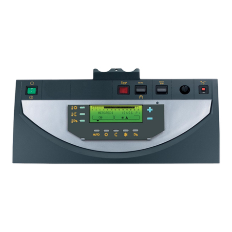
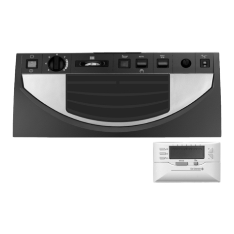
DeDietrich S2NA User manual

GT120 & GT 220A Series
Boiler Control Panel
S2NA Control Panel (Package ME50) EN11/12/09
Installation
instructions
XXXX-XXXX R0
¯ Warning:
This control is approved for use with the De Dietrich GT120A or GT220A series boiler only.
Before you operate youinstall or use this boiler control,read this manual carefully andtake extra precautions toall safety andwarningsymbolsor
important items. The operating manual is part of the documentation along with the boiler. The installer is required to explain the heating system
and boiler operating instructions to the owner.
! Notice:
Pleasereadthismanualandretain forfuturereference. Improperinstallation, adjustment,alteration, serviceormaintenancecancauseinjury,loss
of life or property damage. Refer to this manual for assistance or additional information or consult a qualified installer, service agency or the gas
supplier.
Operating-User
instructions
Technical
instructions
2GT 220A 06/01/09 - XXXX-XXXX R0
0.1 Contents
1 Description..........................................................................................................................................................3
2
2 Description4
2.1 Introduction.5
2.2 Overview.5
2.3 Technical Info..5
3 Installation.11
3.1 Control panel assembly11
3.2 Boiler sensors.11
3.3 Main electrical connection.13
3.5 Prinicipal diagram.
3.6 Basic burner connections
3.6 Commissionning23
4 Maintenance24
5.1 Checking and cleaning the main components24
5.2 Boiler24
5.3 Burner27
6 Stopping the boiler27
7. Spare parts (Exploded View)28
7.1 Boiler body.28
7.2 Boiler casing & Insulation29
7.3 Control30
7.4 Spare parts list31
Symbols used
Important Items
¯ WARNING:
Forproperoperationoftheboilertheseinstructionmustbe flollowed
excactly.
Any repair or service to this control must be done by a qualified and
trained service person or company.
There are no owner serviceable parts on this control, the usage of
Non-OEM parts void any product warranty and approvals.
Themanufactureris not responsible nor held liable foranyimproper
use or failure to maintain this control is good operating condition.
Always Observe the power polarity
This control requires to be earth grounded (bonded)
If the control must be protected from water. If the control has been
subjected to spray or ingest of water, the entire control must be
replaced.
Before servicing this control, all wires must be labeled carefully to
avoidwiringerrors,wiringerrormay leadtopersonalandequipment
damage including loss of life.
¯Caution danger Risk of injury and damage to equipment. Attention must be paid to the warnings on
safety of persons and equipment
!Specific information Information must be kept in mind to maintain comfort
±Reference Refer to another manual or other pages in this instruction manual
3
11/13/09 - XXXX-XXXX R0 GT 220A
.
¯ Alaysfollowthe safetyinstruction describedbeloworlabels
ahdered to the boiler. failure to follow such instruction may result in
personal injury, including loss of life or damage to the boiler and
surronding property.
iNSTRUCTIONS & SAFETY WARNING LABELS: These
instructions and labels must never beremoved or covered. Replace
damaged or illegible instructions and labels.
The boiler casing is not designed for structual support DO NOT
STAND ON OR USE THE BOILER AS A LADDER.
IF YOU SMELL GAS OR COMBUSTION RELATED FUMES,
PROCEED AS FOLLOWS:
`Do not smoke or generate fire or sparks
`Do not operate any electrical devices or switches
`Close the gas supply cock to the appliance
`Open doors and windows
`Warn those present to leave the building
`Do not use any phone in the building
`Call your local gas supplier once outside the building, if you
cannot reach them call the local fire department.
DO NOT USE THE BOILER IF ANY PORTION OF THE CONTROL
SYSTEM HAS BEEN SUBJECTED TO WATER, INGESTED WITH
WATER OR SUBMERGED IN WATER.
IMMEDIATELY CALL YOUR SERVICE COMPANY TO INSPECT
AND REPLACE ALL CONTROLS AND GAS COMPONENTS.
Boiler Modification and spare parts:
This boiler use specific original manufactured parts, the boiler must
not be modified or use non OEM parts, without the written approval
from DDR Americas Inc. De Dietrich Boilers.
Installation, servicing & maintenance of this boiler shall be
completed by a licenced and trained individual, experinced in
hot water boiler heating and gas & oil combustion. The
installationmustconformtoallnationalandlocalcodeshaving
jurisdication:
`In Canada CSA B149.1 Gas Code & CSA B139 Oil Code
`InUSA ANSIZ223.1 (NFPA54) GasCode, NFPA31 OilCode
& ASME CSD-1 Automatically fired boilers.
If you have any technical questions or need assistance with
this product, please call us toll free
1.800.943.6275 E.S.T. Monday thru Friday 08:00 - 17:00 EST
0.2 Description
S2NA control panel is designed specifically for the De Dietrich
GT120-220A series cast iron sectional boilers, they are
approved for use with the above mentioned boiler series, they
are not approved to be used with any other boiler series or
manaufacturers.
The panel is designed for to be used with a power burner
Application(s):
Space heating only
DHW heating possible with seperate control
Single or 2 stage* burners
2 stage
Modulating burner require a seperate control
a single heating circuits non
0.3 Control overview
S2NA Panel overview 1. Wiring terminal strip
4GT 220A 06/01/09 - XXXX-XXXX R0
2. Dial conversion
3. Safety (Fixed Hi-Limit) Limit (manual reset)
4. Fuse breaker 10A
5. 1st stage or operating limit adjustable
6. Provision for optional digital control offering
7. 2nd stage or aux operating limit adjustable
8. MAN/AUTO/STB switch
• Man = basic panel operation
• AUTO = digital control operation
• STB = safety test button (testing of fixed hi limit)
9. Illuminated main On/Off switch
10. AUTO/O/MANU (pump control) not part of the safety or
operating limits)
• AUTO = digital control pump operation
• O = pump off
• MAN = basic panel pump control - pump operates continously
0.4 Technical Info.
Power supply: 120VAC +/- 10% single phase with neutral and
ground earth.
Maximum 10A operation, fuse breaker protected
Safety Hi Limit (Fixed Hi-Limit) 230°F [110°C] +/- 5%
1st stage or operating adjustable limit 104-212°F [40-100°C] dial
increments of 4-10
1
2
4 5 6 7 8 9 10
3
5
11/13/09 - XXXX-XXXX R0 GT 220A
.
2nd stage or aux operating adjustable limit 104-212°F [40-100°C]
dial increments of 4-10
Switches
Main illuminated ON/OFF switch = 250v 12A max
MAN/AUTO/STB switch = 250v 12A max
AUTO/O/MANU switch = 250v 12A max
All Wiring CSA TEW/ UL 1015 18awg. 105°C
Ifburnerloadexceeds120v 10Asingle phase a seperatedisconnect
power supply will be needed for the burner.
0.5 Compliance
The S2NA (ME50 Package) complies with latest standards:
• CSA 22.2 No. 24
• UL 873
• UL 353
• ASME Section IV
• CSA B51
•CSD-1
• Consult factory for other compliance requirements not
mentioned.
0.6 Main electrical connections
¯Only qualified and trained personell shall make electrical
connections.
`All wiring must comply with the latest national and local electrical codes NEC NFPA70 & CSA 22.2
`Main fuse disconnect must be provided 15A max
`Suitable strain relief and wire protection must be provided
`All wiring UL/CSA approved type suitable for the installation
and must be at least 18awg [0.75mm2] rated for 300v 90°C
min.
`The equipment must be earth grounded (bonded)
`No modification to the internal panel wiring
`
The main power is routed through the rear of the panel as shown,
strain reliefs are provided in the accessories packaging with the
panel.
1. Main power supply wires to panel
2. Optional sensors or building control wiring
3. Strain reliefs
Consult typical installation wiring diagrams as shown on the procee-
ding pages.
Always consult the supplied burner wiring diagram
GT 220A Series boilers
GT 120A Series boilers
6GT 220A 06/01/09 - XXXX-XXXX R0
0.7 Panel - burner wiring
Application wiring method #1 (ON/OFF panel operation)
Main power provided to burner then through panel, using then 2nd
stage limit control as a redundant operating limit.
ALL WIRING BETWEEN BURNER AND PANEL AS SHOWN
INSTALLED BY OTHERS
1. Main power disconnect fuse 15A max
2. Service switch (located near boiler in an accessible location)
3. Low water cutoff control (2 possible wiring connections)
4. Vent safety device installed on venting
5. Optional instead of vent safety device a jumper can be installed
between 6-7 if the burner is equipped with a high gas or over
pressure switch (manual reset)
MAN/AUTO/STB Switch
Must be in the MAN position for the basic panel operation.
STB = Testing safety (fixed Hi-limit)
AUTO = Not used no function
BMS or Digital Control Sensor Wiring
4 5 6 7 10 11813 1412 1615 1917 2120 25 28 2927 3130 33 3432 3635 3837
Thermostat
(Optional)
TS
2
3
1
(1) AUTO (1a) STB
(1b)MAN
TCH1
TCH2
ZSTB
ZG
DJ10A
Internal Wiring – By Factory Do not Modify
De Dietrich Control Panels
S2NA (ME50) = GT120-220A Series boilers
S3NA (MD5) = GT330-430-530A Series
(2) AUTO
(2a) STB
(2b) MAN
922 23 24 2618
ZP
(2a) AUTO
(1a) AUTO
(2b) MAN
(1b) MAN
(2) OFF (1) OFF
Optional BMS – Digital Control Wiring
Optional BMS or Digital Control Wiring
Transformer & Pump Wiring
(Not part of safety or operating limits)
N
L
AC Supply
120/60/1 – 15A Max
321
120/60/1
Main Power Supply
CS – Safety
Contact 120v
Burner Connections
Heating
Pump
DHW
Pump
120/24v
Transformer optional
BMS or Digital Control Wiring
1
st
Stage
2
nd
stage
GndN
Only used with Optional
BMS & Digital Control
BURNER CONTROL
POWER
X X
LOW WATER CUTOFF
X XNL
Operator (Limit) Circuit
Gnd
1 2 3
4
4
X= Burner terminals - not all terminal designations shown
3*
5
Open terminals
Panel Internal Wiring Legend
symbol Description
ZG main power switch
Earth Ground
DJ 10A Fuse breaker
TS – Safety limit (SPDT) manual reset
Panel wire terminals
ZSTB switch Man/Auto/STB
TCH1 – 1st stage or
limit control
TCH2 – Aux Limit or 2nd stage Limit (optional usage)
ZP – Aux (pump) switch AUTO/OFF/MAN
1
Common connection
All wiring min 18awg. (16 strd) type
CSA TEW or UL1015 (rated for at least 300v - 90°C)
All panels to be earth leakage test (Di-electric) and function tested
All components North American approved (see material listing)
Factory wiring Line
(Hot or L1)
Factory wiring Neutral
(N or L2)
Blocked vent safety interlock
(jumper if burner equipped)
ZSTB
switch
ZP
AUTO
MAN
STB
OFF
MAN
AUTO
ATTENTION – WARNING
FAILURE TO FOLLOWING THIS WIRING DIAGRAM MAY RESULT IN PROPERTY
DAMAGE OR PERSONAL INJURY INCLUDING DEATH.
Wiring must be in strict compliance with CSA C22.2 and NEC/NFPA 70.
All wiring shown supplied and wired by others.
Panel 2
nd
Stage output used 2-stage limit control or as a auxiliary limit works with the
1
st
limit.
This equipment must be earth bonded or grounded.
All wiring (field or replacement) must be min 18AWG type CSA TEW/ UL 1015 rated
300v - 90°C minimum.
All wiring and panels must be shielded from spray or ingestion of water.
Any portion of the control which has been subject to spray or ingestion of water, the
entire control must be replaced.
It is the responsibility of the installer/owner to verify the controls are functioning
correctly and are adjusted correctly.
Suitable wire protection and strain relief’s are required (upstream & downstream) of
the control panel.
Line voltage wiring and low voltage sensor wiring must use separate wire conduits.
LABEL ALL WIRES PRIOR TO DISCONNECTING THEM FOR SERVICE.
7
11/13/09 - XXXX-XXXX R0 GT 220A
.
0.8 Panel - Burner wiring
Application Method # 2 (ON/OFF panel operation)
Main power provided to panel then to burner, for burner that do not
require a constant uniterupted power.
ALL WIRING BETWEEN BURNER AND PANEL AS SHOWN
INSTALLED BY OTHERS
1. Main power disconnect fuse 15A max
2. Service switch (located near boiler in an accessible location)
3. Low water cutoff control (2 possible wiring connections)
4. Vent safety device installed on venting
5. Optional instead of vent safety device a jumper can be installed
between 6-7 if the burner is equipped with a high gas or over
pressure switch (manual reset) power disconnect fuse 15A max
Wiring does not show burner motor connections or firing controls
needed for 2 stage or modulating burners. This control are not pro-
vided and are by others.
MAN/AUTO/STB Switch
MustbeintheMANpositionforthebasicpaneloperation.
STB = Testing safety (fixed Hi-limit)
AUTO = Not used no function
BMS or Digital Control Sensor Wiring
4 5 6 7 10 1181
3
1
4
1
2
1
6
1
5
1
9
1
7
2
1
2
0
2
5
2
8
2
9
2
7
3
1
3
0
3
3
3
4
3
2
3
6
3
5
3
8
3
7
Thermostat
(Optional)
TS
2
3
1(1)
AUTO (1a) STB
(1b)MAN
TCH1
TCH2
ZSTB
ZG
DJ10A
Internal Wiring – By Factory Do not Modify
De Dietrich Control Panels
S2NA (ME50) = GT120-220A Series boilers
S3NA (MD5) = GT330-430-530A Series
(2)
AUTO
(2a) STB
(2b)
MAN
92
2
2
3
2
4
2
6
1
8
ZP
(2a)
AUTO
(1a)
AUTO
(2b)
MAN
(1b)
MAN
(2) OFF (1)OFF
Optional BMS – Digital Control Wiring
Optional BMS or Digital Control Wiring
Transformer & Pump Wiring
(Not part of safety or operating limits)
NL
AC Supply
120/60/1 – 15A Max
321
120/60/1
Main Power Supply
CS – Safety
Contact 120v
Burner Connections
Heating
Pump
DHW
Pump
120/24v
Transformer optional
BMS or Digital Control Wiring
1st
Stage
2nd
stage
GndN
Only used with Optional
BMS & Digital Control
NL Gnd
1
2
34
4
X
= Burner terminals - not all
terminal designations shown
5
3*
7
Open terminals
ATTENTION – WARNING
FAILURE TO FOLLOWING THIS WIRING DIAGRAM MAY RESULT IN PROPERTY
DAMAGE OR PERSONAL INJURY INCLUDING DEATH.
Wiring must be in strict compliance with CSA C22.2 and NEC/NFPA 70.
All wiring shown supplied and wired by others.
Panel 2
nd
Stage output used 2-stage limit control or as a auxiliary limit works with the
1
st
limit.
This equipment must be earth bonded or grounded.
All wiring (field or replacement) must be min 18AWG type CSA TEW/ UL 1015 rated
300v - 90°C minimum.
All wiring and panels must be shielded from spray or ingestion of water.
Any portion of the control which has been subject to spray or ingestion of water, the
entire control must be replaced.
It is the responsibility of the installer/owner to verify the controls are functioning
correctly and are adjusted correctly.
Suitable wire protection and strain relief’s are required (upstream & downstream) of
the control panel.
Line voltage wiring and low voltage sensor wiring must use separate wire conduits.
LABEL ALL WIRES PRIOR TO DISCONNECTING THEM FOR SERVICE.
Panel Internal Wiring Legend
symbol Description
ZG main power switch
Earth Ground
DJ 10A Fuse breaker
TS – Safety limit (SPDT) manual reset
Panel wire terminals
ZSTB switch Man/Auto/STB
TCH1 – 1st stage or
limit control
TCH2 – Aux Limit or 2nd stage Limit (optional usage)
ZP – Aux (pump) switch AUTO/OFF/MAN
1
Common connection
All wiring min 18awg. (16 strd) type
CSA TEW or UL1015 (rated for at least 300v - 90°C)
All panels to be earth leakage test (Di-electric) and function tested
All components North American approved (see material listing)
Factory wiring Line
(Hot or L1)
Factory wiring Neutral
(N or L2)
Blocked vent safety interlock
(jumper if burner equipped)
ZSTB
switch
ZP
AUTO
MAN
STB
OFF
MAN
AUTO
8GT 220A 06/01/09 - XXXX-XXXX R0
BMS or Digital Control Sensor Wiring
4 5 6 7 10 11813 1412 1615 1917 2120 25 28 2927 3130 33 3432 3635 3837
Thermostat
(Optional)
TS
2
3
1
(1) AUTO (1a) STB
(1b)MAN
TCH1
TCH2
ZSTB
ZG
DJ10A
Internal Wiring – By Factory Do not Modify
De Dietrich Control Panels
S2NA (ME50) = GT120-220A Series boilers
S3NA (MD5) = GT330-430-530A Series
(2) AUTO
(2a) STB
(2b) MAN
922 23 24 2618
ZP
(2a) AUTO
(1a) AUTO
(2b) MAN
(1b) MAN
(2) OFF (1)OFF
Optional BMS – Digital Control Wiring
Optional BMS or Digital Control Wiring
Transformer & Pump Wiring
(Not part of safety or operating limits)
N
L
AC Supply
120/60/1 – 15A Max
321
120/60/1
Main Power Supply
CS – Safety
Contact 120v
Burner Connections
Heating
Pump
DHW
Pump
120/24v
Transformer optional
BMS or Digital Control Wiring
1
st
Stage
2
nd
stage
GndN
Only used with Optional
BMS & Digital Control
BURNER CONTROL
POWER
X X X XNL
Limit Circuit (Operator)
Gnd
1 2 3
4
4
X
= Burner terminals - not all
terminal designations shown
3*
k1
2
ND
stage limit circuit
(2
nd
stage operator)
Open terminals
0.9 Panel - burner wiring
Application Method # 3: 2 stage operation (L-H-L)
Main power provided to panel then to burner,
ALL WIRING BETWEEN BURNER AND PANEL AS SHOWN
INSTALLED BY OTHERS
1. Main power disconnect fuse 15A max
2. Service switch (located near boiler in an accessible location)
3. Low water cutoff control (2 possible wiring connections)
4. Vent safety device installed on venting
5. Optional instead of vent safety device a jumper can be installed
between 6-7 if the burner is equipped with a high gas or over
pressure switch (manual reset) power disconnect fuse 15Amax
Wiring does not show burner motor connections or firing controls
needed for 2 stage or modulating burners. This control are not pro-
vided and are by others.
MAN/AUTO/STB Switch
Mustbe intheMAN positionfor thebasic panel operation.
STB = Testing safety (fixed Hi-limit)
AUTO = Not used no function
ATTENTION – WARNING
FAILURE TO FOLLOWING THIS WIRING DIAGRAM MAY RESULT IN PROPERTY
DAMAGE OR PERSONAL INJURY INCLUDING DEATH.
Wiring must be in strict compliance with CSA C22.2 and NEC/NFPA 70.
All wiring shown supplied and wired by others.
Panel 2
nd
Stage output used 2-stage limit control or as a auxiliary limit works with the
1
st
limit.
This equipment must be earth bonded or grounded.
All wiring (field or replacement) must be min 18AWG type CSA TEW/ UL 1015 rated
300v - 90°C minimum.
All wiring and panels must be shielded from spray or ingestion of water.
Any portion of the control which has been subject to spray or ingestion of water, the
entire control must be replaced.
It is the responsibility of the installer/owner to verify the controls are functioning
correctly and are adjusted correctly.
Suitable wire protection and strain relief’s are required (upstream & downstream) of
the control panel.
Line voltage wiring and low voltage sensor wiring must use separate wire conduits.
LABEL ALL WIRES PRIOR TO DISCONNECTING THEM FOR SERVICE.
Panel Internal Wiring Legend
symbol Description
ZG main power switch
Earth Ground
DJ 10A Fuse breaker
TS – Safety limit (SPDT) manual reset
Panel wire terminals
ZSTB switch Man/Auto/STB
TCH1 – 1st stage or
limit control
TCH2 – Aux Limit or 2nd stage Limit (optional usage)
ZP – Aux (pump) switch AUTO/OFF/MAN
1
Common connection
All wiring min 18awg. (16 strd) type
CSA TEW or UL1015 (rated for at least 300v - 90°C)
All panels to be earth leakage test (Di-electric) and function tested
All components North American approved (see material listing)
Factory wiring Line
(Hot or L1)
Factory wiring Neutral
(N or L2)
Blocked vent safety interlock
(jumper if burner equipped)
ZSTB
switch
ZP
AUTO
MAN
STB
OFF
MAN
AUTO
9
11/13/09 - XXXX-XXXX R0 GT 220A
.
0.10 Panel - Burner Wiring
Applicationwiring:2Stageoperation(L-H-L)mainpowerprovided
to panel then to burner.
ALL WIRING BETWEEN BURNER AND PANEL AS SHOWN
INSTALLED BY OTHERS
1. Main power disconnect fuse 15A max
2. Service switch (located near boiler in an accessible location)
3. Low water cutoff control (2 possible wiring connections)
4. Vent safety device installed on venting
5. Optional instead of vent safety device a jumper can be installed
between 6-7 if the burner is equipped with a high gas or over
pressure switch (manual reset) power disconnect fuse 15A max
Wiring does not show burner motor connections or firing controls
needed for 2 stage or modulating burners. This control are not pro-
vided and are by others.
MAN/AUTO/STB Switch
Must be in the MAN position for the basic panel operation.
STB = Testing safety (fixed Hi-limit)
AUTO = Not used no function
BMS or Digital Control Sensor Wiring
4 5 6 7 10 11813 1412 1615 1917 2120 25 28 2927 3130 33 3432 3635 3837
Thermostat
(Optional)
TS
2
3
1
(1) AUTO (1a)STB
(1b)MAN
TCH1
TCH2
ZSTB
ZG
DJ10A
Internal Wiring – By Factory Do not Modify
De Dietrich Control Panels
S2NA (ME50) = GT120-220A Series boilers
S3NA (MD5) = GT330-430-530A Series
(2) AUTO
(2a) STB
(2b) MAN
922 23 24 2618
ZP
(2a) AUTO
(1a) AUTO
(2b) MAN
(1b) MAN
(2) OFF (1) OFF
Optional BMS – Digital Control Wiring
Optional BMS or Digital Control Wiring
Transformer & Pump Wiring
(Not part of safety or operating limits)
NL
AC Supply
120/60/1 – 15A Max
321
120/60/1
Main Power Supply
CS – Safety
Contact 120v
Burner Connections
Heating
Pump
DHW
Pump
120/24v
Transformer optional BMS or Digital Control Wiring
1
st
Stage
2
nd
stage GndN
Only used with Optional
BMS & Digital Control
BURNER CONTROL
POWER
NLGnd
1
2
3
4
4
X
= Burner terminals - not all terminal designations shown
3*
X X
k1
X X
Limit Circuit
(Operator)
2
nd
stage Limit Circuit
(Operator)
Open terminals
ATTENTION – WARNING
FAILURE TO FOLLOWING THIS WIRING DIAGRAM MAY RESULT IN PROPERTY
DAMAGE OR PERSONAL INJURY INCLUDING DEATH.
Wiring must be in strict compliance with CSA C22.2 and NEC/NFPA 70.
All wiring shown supplied and wired by others.
Panel 2
nd
Stage output used 2-stage limit control or as a auxiliary limit works with the
1
st
limit.
This equipment must be earth bonded or grounded.
All wiring (field or replacement) must be min 18AWG type CSA TEW/ UL 1015 rated
300v - 90°C minimum.
All wiring and panels must be shielded from spray or ingestion of water.
Any portion of the control which has been subject to spray or ingestion of water, the
entire control must be replaced.
It is the responsibility of the installer/owner to verify the controls are functioning
correctly and are adjusted correctly.
Suitable wire protection and strain relief’s are required (upstream & downstream) of
the control panel.
Line voltage wiring and low voltage sensor wiring must use separate wire conduits.
LABEL ALL WIRES PRIOR TO DISCONNECTING THEM FOR SERVICE.
Panel Internal Wiring Legend
symbol Description
ZG main power switch
Earth Ground
DJ 10A Fuse breaker
TS – Safety limit (SPDT) manual reset
Panel wire terminals
ZSTB switch Man/Auto/STB
TCH1 – 1st stage or
limit control
TCH2 – Aux Limit or 2nd stage Limit (optional usage)
ZP – Aux (pump) switch AUTO/OFF/MAN
1
Common connection
All wiring min 18awg. (16 strd) type
CSA TEW or UL1015 (rated for at least 300v - 90°C)
All panels to be earth leakage test (Di-electric) and function tested
All components North American approved (see material listing)
Factory wiring Line
(Hot or L1)
Factory wiring Neutral
(N or L2)
Blocked vent safety interlock
(jumper if burner equipped)
ZSTB
switch
ZP
AUTO
MAN
STB
OFF
MAN
AUTO
10 GT 220A 06/01/09 - XXXX-XXXX R0
0.11 Panel - Burner wiring
Application wiring: Typical Riello or Weishaupt Burner, 2 Stage
operation (L-H-L) main power provided to panel thento burner.
ALL WIRING BETWEEN BURNER AND PANEL AS SHOWN
INSTALLED BY OTHERS
1. Main power disconnect fuse 15A max
2. Service switch (located near boiler in an accessible location)
3. Low water cutoff control (2 possible wiring connections)
4. Vent safety device installed on venting
5. Optional instead of vent safety device a jumper can be installed
between 6-7 if the burner is equipped with a high gas or over
pressure switch (manual reset) power disconnect fuse 15Amax
Wiring does not show burner motor connections or additional bur-
nerwiring required.2 stage operation requires a 2 stage firing relay
as shown in the diagram, this firing relay is sold as an option and is
not provided with the standard panel, unless specifically ordered.
MAN/AUTO/STB Switch
MAN = position for the basic panel operation.
STB = Testing safety (fixed Hi-limit)
AUTO = Not used no function
BMS or Digital Control Sensor Wiring
4 5 6 7 10 1181
3
1
4
1
2
1
6
1
5
1
9
1
7
2
1
2
0
2
5
2
8
2
9
2
7
3
1
3
0
3
3
3
4
3
2
3
6
3
5
3
8
3
7
Thermostat
(Optional)
TS
2
3
1
(1)
AUTO (1a) STB
(1b)MAN
TCH1
TCH2
ZSTB
ZG
DJ10A
Internal Wiring – By Factory Do not Modify
De Dietrich Control Panels
S2NA (ME50) = GT120-220A Series boilers
S3NA (MD5) = GT330-430-530A Series
(2)
AUTO
(2a) STB
(2b)
MAN
92
2
2
3
2
4
2
6
1
8
ZP
(2a)
AUTO
(1a)
AUTO
(2b)
MAN
(1b)
MAN
(2) OFF (1) OFF
Optional BMS – Digital Control Wiring
Optional BMS or Digital Control Wiring
Transformer & Pump Wiring
(Not part of safety or operating limits)
NL
AC Supply
120/60/1 – 15A Max
321
120/60/1
Main Power Supply
CS – Safety
Contact
120v
Burner Connections
Heating
Pump
DHW
Pump
120/24v
Transformer optional
BMS or Digital Control Wiring
1
st
Stage
2
nd
stage
GndN
Only used with Optional
BMS & Digital Control
BURNER
CONTROL POWER
NLGnd
1
2
3
4
4
X
= Burner terminals - not all terminal
designations shown
3
*
T6 T7 T8
k
1
T1 T2
Limit Circuit
(Operator)
2
nd
Stage Limit Circuit (2
nd
stage operator)
Open terminals
ATTENTION – WARNING
FAILURE TO FOLLOWING THIS WIRING DIAGRAM MAY RESULT IN PROPERTY
DAMAGE OR PERSONAL INJURY INCLUDING DEATH.
Wiring must be in strict compliance with CSA C22.2 and NEC/NFPA 70.
All wiring shown supplied and wired by others.
Panel 2
nd
Stage output used 2-stage limit control or as a auxiliary limit works with the
1
st
limit.
This equipment must be earth bonded or grounded.
All wiring (field or replacement) must be min 18AWG type CSA TEW/ UL 1015 rated
300v - 90°C minimum.
All wiring and panels must be shielded from spray or ingestion of water.
Any portion of the control which has been subject to spray or ingestion of water, the
entire control must be replaced.
It is the responsibility of the installer/owner to verify the controls are functioning
correctly and are adjusted correctly.
Suitable wire protection and strain relief’s are required (upstream & downstream) of
the control panel.
Line voltage wiring and low voltage sensor wiring must use separate wire conduits.
LABEL ALL WIRES PRIOR TO DISCONNECTING THEM FOR SERVICE.
Panel Internal Wiring Legend
symbol Description
ZG main power switch
Earth Ground
DJ 10A Fuse breaker
TS – Safety limit (SPDT) manual reset
Panel wire terminals
ZSTB switch Man/Auto/STB
TCH1 – 1st stage or
limit control
TCH2 – Aux Limit or 2nd stage Limit (optional usage)
ZP – Aux (pump) switch AUTO/OFF/MAN
1
Common connection
All wiring min 18awg. (16 strd) type
CSA TEW or UL1015 (rated for at least 300v - 90°C)
All panels to be earth leakage test (Di-electric) and function tested
All components North American approved (see material listing)
Factory wiring Line
(Hot or L1)
Factory wiring Neutral
(N or L2)
Blocked vent safety interlock
(jumper if burner equipped)
ZSTB
switch
ZP
AUTO
MAN
STB
OFF
MAN
AUTO
11
11/13/09 - XXXX-XXXX R0 GT 220A
.
0.12 Optional Panel - Burner wiring with BMS
Application wiring: Example burner wiring 2 stage (L-H-L)
operation, main power provided to panel then to burner.
ALL WIRING BETWEEN BURNER AND PANEL AS SHOWN
INSTALLED BY OTHERS
1. Main power disconnect fuse 15A max
2. Service switch (located near boiler in an accessible location)
3. Low water cutoff control (2 possible wiring connections)
4. Vent safety device installed on venting
5. Optional instead of vent safety device a jumper can be installed
between 6-7 if the burner is equipped with a high gas or over
pressure switch (manual reset) power disconnect fuse 15A max
Wiring does not show burner motor connections or additional bur-
nerwiring required.2 stage operation requires a 2stagefiringrelay
as shown in the diagram, this firing relay is sold as an option and is
not provided with the standard panel, unless specifically ordered.
MAN/AUTO/STB Switch
MAN = Position for the basic panel operation.
STB = Testing safety (fixed Hi-limit)
AUTO = Position remote BMS operation
BMS or Digital Control Sensor Wiring
4 5 6 7 10 11813 1412 1615 1917 2120 25 28 2927 3130 33 3432 3635 3837
Thermostat
(Optional)
TS
2
3
1
(1)
AUTO (1a) STB
(1b)MAN
TCH1
TCH2
ZSTB
ZG
DJ10A
Internal Wiring – By Factory Do not Modify
De Dietrich Control Panels
S2NA (ME50) = GT120-220A Series boilers
S3NA (MD5) = GT330-430-530A Series
(2)
AUTO
(2a) STB
(2b)
MAN
922 23 24 2618
ZP
(2a)
AUTO
(1a)
AUTO
(2b)
MAN
(1b)
MAN
(2) OFF (1) OFF
NL
AC Supply
120/60/1 – 15A Max
321
120/60/1
Main Power Supply
CS – Safety
Contact 120v
Burner Connections
Heating
Pump
DHW
Pump
120/24v
Transformer BMS or Digital Control Wiring
1
st
Stage
2
nd
stage GndN
Only used with Optional
BMS & Digital Control
L
1
2
3
4
4
X= Burner terminals - not all
terminal designations shown
3*
BMS (Remote)
x x
L N
NL
x x x x x x
All contact must be (dry)
Operator (Limit)
1 stage control
Operator (Limit)
2 stage control
Heating
Pump Control
DHW Pump
Control
Open terminals
NGND X X
k1
X X
Limit circuit
(Operator)
2
nd
stage
Limit circuit
(Operator)
Panel Internal Wiring Legend
symbol Description
ZG main power switch
Earth Ground
DJ 10A Fuse breaker
TS – Safety limit (SPDT) manual reset
Panel wire terminals
ZSTB switch Man/Auto/STB
TCH1 – 1
st
stage or
limit control
TCH2 – Aux Limit or 2
nd
stage Limit (optional usage)
ZP – Aux (pump) switch AUTO/OFF/MAN
1
Common connection
All wiring min 18awg. (16 strd) type
CSA TEW or UL1015 (rated for at least 300v - 90°C)
All panels to be earth leakage test (Di-electric) and function tested
All components North American approved (see material listing)
Factory wiring Line
(Hot or L1)
Factory wiring Neutral
(N or L2)
Blocked vent safety interlock
(jumper if burner equipped)
ZSTB
switch
ZP
AUTO
MAN
STB
OFF
MAN
AUTO
ATTENTION – WARNING
FAILURE TO FOLLOWING THIS WIRING DIAGRAM MAY RESULT IN PROPERTY
DAMAGE OR PERSONAL INJURY INCLUDING DEATH.
Wiring must be in strict compliance with CSA C22.2 and NEC/NFPA 70.
All wiring shown supplied and wired by others.
Panel 2
nd
Stage output used 2-stage limit control or as a auxiliary limit works with the
1
st
limit.
This equipment must be earth bonded or grounded.
All wiring (field or replacement) must be min 18AWG type CSA TEW/ UL 1015 rated
300v - 90°C minimum.
All wiring and panels must be shielded from spray or ingestion of water.
Any portion of the control which has been subject to spray or ingestion of water, the
entire control must be replaced.
It is the responsibility of the installer/owner to verify the controls are functioning
correctly and are adjusted correctly.
Suitable wire protection and strain relief’s are required (upstream & downstream) of
the control panel.
Line voltage wiring and low voltage sensor wiring must use separate wire conduits.
LABEL ALL WIRES PRIOR TO DISCONNECTING THEM FOR SERVICE.
12 GT 220A 06/01/09 - XXXX-XXXX R0


T
TT
T


























T
TT
T









 

 






 














  
!""#!#"#$%#&#$%#
&!""#!#"$%!#%&
&!""#!#"!!"'%&&
!"!!&#
!"%$!!#"&!(!)!"%$
!"%$!#&!"!*''#"!$&'!"!"%$+,!
!"%$!#&!"!-''#"!$&'!"!"%$.!
!#"!!#"'
%#!'
!!!
"#'!#"#"!"
!##!&&"!$%!&$!""#
& $!#"
&"#&"!/!"
"$ %
!""!!"
&
""!!$!&$"
$%!!"!
$%!#((!!&#%
'$#%
'
''
'
%#'
"($"%!#"010"($"%!"010
'
''
'
'
''
'
'
''
'
'
''
'
$!!#"&!(!)$

0.13 Principle wirig diagram
13
11/13/09 - XXXX-XXXX R0 GT 220A
.
0.1
55
56
57 58 58 59 60 61
14 GT 220A 06/01/09 - XXXX-XXXX R0
15
11/13/09 - XXXX-XXXX R0 GT 220A
.
The Manufacturer:
Bp 30 – 57, RUE DE LA Gare
F – 67580 MERTZWILLER
Tel: +33/3/88/80/27/00 – Fax: +33/3 88 80 27 99
Ni IRC : 347 555 559 RCS STRASBOURG
www.dedietrich-thermique.com
DDR AMERICAS INC
.
In Canada:
1090 Fountain St., Unit #10
Cambridge, Ontario, N3E 1A3 - CANADA
Tel: 519.650.0420 Fax: 519.650.1709
In USA or South America:
1054 North DuPage Avenue
Lombard, Illinois, USA 60148
Tel: 630.953.2374 Fax: 630.953.2376
Toll Free 1.800.943.6275
www.dedietrichboilers.com
In the interest of customers, DE DIETRICH & DDR Americas are continuously endeavouring to make improvements in product quality.
All the specifications stated in this document are therefore subject to change without notice

This manual suits for next models

1

Other DeDietrich Control Panel manuals

DeDietrich S3 User manual

DeDietrich

DeDietrich S3 User manual

DeDietrich MIT/E iSystem User manual

DeDietrich

DeDietrich MIT/E iSystem User manual

DeDietrich IniControl Troubleshooting guide

DeDietrich

DeDietrich IniControl Troubleshooting guide

DeDietrich EASYMATIC User manual

DeDietrich

DeDietrich EASYMATIC User manual

DeDietrich DIEMATIC 3 User manual

DeDietrich

DeDietrich DIEMATIC 3 User manual

DeDietrich B control panel User manual

DeDietrich

DeDietrich B control panel User manual

DeDietrich Diematic iSystem Troubleshooting guide

DeDietrich

DeDietrich Diematic iSystem Troubleshooting guide

DeDietrich IniControl 2 Operating instructions

DeDietrich

DeDietrich IniControl 2 Operating instructions

Popular Control Panel manuals by other brands

Gemini GEM-P801 datasheet

Gemini

Gemini GEM-P801 datasheet

DITEC CS12M installation manual

DITEC

DITEC CS12M installation manual

Bender COMTRAXX CP305 quick start guide

Bender

Bender COMTRAXX CP305 quick start guide

Turbo E8T Use and maintenance instructions

Turbo

Turbo E8T Use and maintenance instructions

UTC Fire and Security ZP1-X3E Series installation manual

UTC Fire and Security

UTC Fire and Security ZP1-X3E Series installation manual

S&G SG-0007C user manual

S&G

S&G SG-0007C user manual

Satel INTEGRA Plus Programming manual

Satel

Satel INTEGRA Plus Programming manual

Frick QUANTUM Series Setup

Frick

Frick QUANTUM Series Setup

Chamberlain MyQ 889LM manual

Chamberlain

Chamberlain MyQ 889LM manual

Maple Armor FW106S,FW106SC Installation and operation manual

Maple Armor

Maple Armor FW106S,FW106SC Installation and operation manual

Sole Diesel SCO 11 Operator's manual

Sole Diesel

Sole Diesel SCO 11 Operator's manual

Cofem CLVR08Z manual

Cofem

Cofem CLVR08Z manual

Dometic MPC01 Installation and operating manual

Dometic

Dometic MPC01 Installation and operating manual

Technisonic Industries Limited TDAP-611 installation instructions

Technisonic Industries Limited

Technisonic Industries Limited TDAP-611 installation instructions

Teletek electronics ECLIPSE 8 User's operation manual

Teletek electronics

Teletek electronics ECLIPSE 8 User's operation manual

Maple Systems OIT3185 installation manual

Maple Systems

Maple Systems OIT3185 installation manual

Emerson NELSON HEAT TRACE SMMC-3 manual

Emerson

Emerson NELSON HEAT TRACE SMMC-3 manual

MZ electronic NAUTI220 Technical manual

MZ electronic

MZ electronic NAUTI220 Technical manual

manuals.online logo
manuals.online logoBrands
  • About & Mission
  • Contact us
  • Privacy Policy
  • Terms and Conditions

Copyright 2025 Manuals.Online. All Rights Reserved.