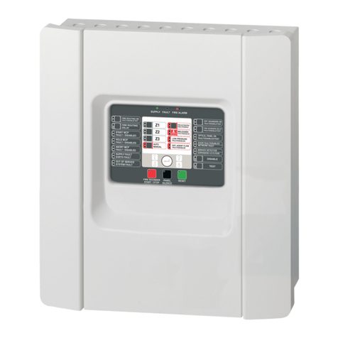
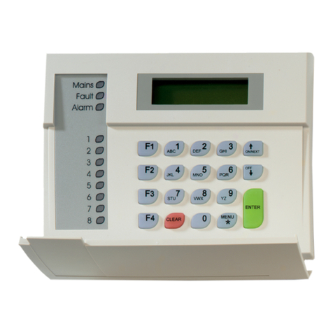
Aritech ATS4000 Operating instructions

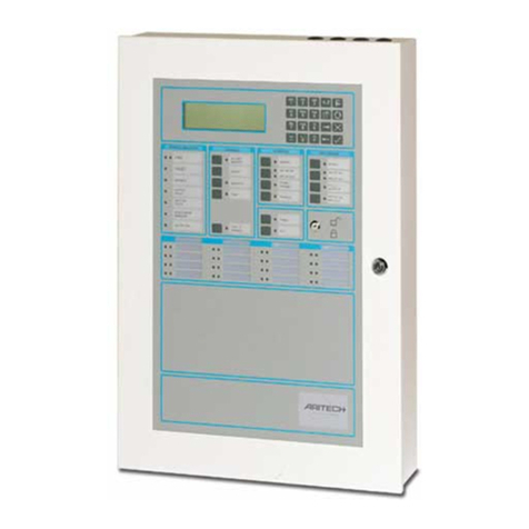
ATS4000 Control Panel
Installation and
Quick Programming Guide
Version 1.0

A
ritech is an interlogiX Company
© interlogix B.V. 2000. All rights reserved. No part of this publication may be reproduced, transmitted, stored in a retrieval system, or
transmitted in any form, or by any means – electronic, photocopying, recording, or otherwise – without the prior written permission of
interlogiX B.V.. interlogiX B.V. reserve the right to change information without notice.

ATS4000 Installation and Quick Programming Guide 1
CONTENTS
Installation ........................................................................................................................................................ 2
1. Control Panel ................................................................................................................................. 2
2. Important notes on mounting......................................................................................................... 2
3. LED’s ............................................................................................................................................. 2
4. Cabling........................................................................................................................................... 3
System databus connection diagram preferred wiring. ................................................................. 3
5. System databus connection .......................................................................................................... 4
6. Earthing ......................................................................................................................................... 4
7. Mounting ........................................................................................................................................ 5
8. Mounting the hardware – Addressing............................................................................................5
8-32 zone DGP programming (ATS 1201) .................................................................................... 5
Outputs .......................................................................................................................................... 5
Siren outputs ................................................................................................................................. 6
Output control groups .................................................................................................................... 6
Door and lift numbering ................................................................................................................. 6
Technical specifications.................................................................................................................................. 6
1. Specification ATS4000 Main Board (no accessories) ................................................................... 7
2. Specification External terminals .................................................................................................... 7
3. 7
4. Values for end-of-line resistors...................................................................................................... 7
5. Connection diagrams..................................................................................................................... 8
Quick Programming guide .............................................................................................................................. 9
1. Defaulting the panel to factory defaults ......................................................................................... 9
2. Powering up the panel................................................................................................................... 9
3. Disarming the system .................................................................................................................... 9
4. Entering the ATS menu ................................................................................................................. 9
5. Entering the programming menu to program the system.............................................................. 9
6. Changing parameters in the programming (examples)............................................................... 10
Default the panel ......................................................................................................................... 10
Programming zones .................................................................................................................... 10
Program users ............................................................................................................................. 10
7. Programming sequences............................................................................................................. 10
Programming map ......................................................................................................................................... 11

2ATS4000 Installation and Quick Programming Guide
INSTALLATION
1. Control Panel
①Earth plug for shields from data
cable
②Eprom (Factory fitted)
③Flash
④RAM or IUM (optional)
⑤TST1 restore master user code
⑥TST 2 factory use only
J2-J6 Zones
J7 Interface to ATS1202 input
expanders
J8 Clock-out Interface to plug on
output expansion
J9 On board relay output.
J10 RS485 system databus and box
tamper connections
J11 Connector to printer or printer/PC
board (ATS3000/4000)
J13 Siren and strobe connections
J14 Auxiliary power output
J15 Not fitted
J16 PSTN line connection
J17 Power connections
J18 Serial connection (RS232)
J19 RJ11 PTT connection
J20 Connector to ISDN/Audio
Mains Power connection
Use the Mains Connector Terminal for connecting the mains-supply. A fixed cable or a flexible mains lead to an
earthed mains outlet can be used. In case fixed wiring is used, insert a dedicated circuit breaker in the power
distribution network.
IMPORTANT: Disconnect the mains power before opening the cabinet!
•Disconnect AC mains plug from AC Mains wall socket. or
•Disconnect the mains with the dedicated circuit breaker.
2. Important notes on mounting
Minimum clearance between equipment enclosures:
50 mm (between equipment vents)
Minimum clearance between enclosure and sidewall:
25 mm
✍Only use units in a clean environment and not
in humid air.
3. LED’s
L1: Flashes slowly when the panel is operating
(the microprocessor is running)
Rx: Yellow LED flashes when remote units (RAS
and DGP) are replying to polling.
Tx: Red LED flashes when panel is polling remote
unit(s). It must always be active.
Rx1: Yellow LED flashes when data is being
received from a device connected to the PTT
line (J15/J16/J19) (central station or dialler
modem) or J18 (serial port (RS232 PC).
Tx1: Red LED flashes when data is being sent
from the panel to a device connected to the
PTT line (J15/J16) or J18 serial port.
J6
1 C 2 C 3 C
①
X
S+ S- S+ S- + -
F5 F4 F3 F2 F1
NC C NO
J5
4 C 5 C 6 C
J4
7 C 8 C 9 C
J3
10 C 11 C 1 2 C
J2
13 C 14 C 15 C16 C
J11
J7
RAM/IUM
FLASH
EPROM
J15
J19
J16
J18 J20
TST1 TST2
+12V
9-16
ISP
A B AX BX EA
KILL
12V RX TX 0V
J17
J14
J13
J10
J9 J8
Trans-
former
12 VDC Battery
Mains
Termina l
L1
RX
TX1
RX1
TX

ATS4000 Installation and Quick Programming Guide 3
4. Cabling
System databus connection diagram preferred wiring.
The “TERM” link is on the first and last devices
on the system databus. In a “star” wiring
configuration, the “TERM” link is only fitted
on the devices at the ends of the two longest
system databus cable runs.
➀TERM link fitted (first device
on local databus)
➁GND link fitted
➂Control Panel ATS4000
➃TERM link not fitted
➄Remote arming station
➅Separate 12 V power supply. Required if
RAS is more than 100 m from the nearest
panel or DGP. Connect “-“ to “-“ of the
databus
➆TERM link fitted (last device on
local databus)
➇Any data gathering panel like ATS1201
➈Preferred data cable type is
Belden 8723 (2 pair twisted).
➉System earth.
See: System databus connection and Earthing details on page 4
➈
➅
+
-
➃
SW1
SW2
+12 0V D+ D- IN OUT
Rx
Tx
ATS1105
➄
470
Ω
ATS1201
➇
➆
②
0
VD
+
D
-
+12345678-
470
Ω
②
ATS3000/4000.
③
+-
D
+
D
-
J14
J13
J16
J17
J6 J5 J4 J3 J2
J18
J8
J20
RX
TX
RX1
TX1
TH7
TH3
TH5
TH2
TH4
①
470
Ω
➉
EPROM
FLASH
RAM/IUM
J15
J7
RS
COMMS
J19
J10
J9
J2
J3
J3
J4
J6
J7
J8

4ATS4000 Installation and Quick Programming Guide
5. System databus connection
The system databus is used to connect Data
Gathering Panels (to provide extra zones) and
Arming Stations to the ATS control panel. Remote
devices can be up to 1.5 km from an ATS control
panels.
Arming stations and Data Gathering Panels must
be connected via a 2 pair twisted shielded data
cable from the system databus connection.
(Belden 8723 is recommended)
The shield of the data cable should be connected
to earth at the ATS control panel and should be
left disconnected at any other end.
It is recommended that where the distance
between the arming station and the nearest
device is more than 100 meters, a separate power
supply must be used to power the arming station.
To power the arming station, do not connect ‘+’
from the system databus. Connect '+' of the local
power supply to '+' on the arming station and
connect 0 volts from the power supply and 0 volts
from the system databus to the arming station
terminal marked ‘-’.
See Cabling on pages 3.
6. Earthing
WARNING! Correct Earthing
procedure must be followed.
•Earthing of one cabinet containing several
devices.
All devices designed for the system have earth
connections via metal studs to the metal housing.
Take care, that these metal studs make good
connection to the housing (beware of paint).
The earth connections of every piece of
equipment in the system can be used for
connecting the shielding of shielded cables.
If a device is placed in a plastic housing the earth
lug of this device does not have to be connected.
•Earthing panels in a single building.
In one building several cabinets or devices are
earthed to safety ground.
The safety earth of this building has to be checked
by a licensed contractor.
•Earthing panels in more buildings.
If the wiring extends to separated buildings, more
than one common earth system will be used. Use
isolater/repeaters ATS1740 to isolate the system
databus. In this way the system is protected
against variations in earth potential.
Shielding
The shielding of all shielded cables used in the
system should only be connected at ONE side to
one common earthing point in a building (see
figure). If a shielded databus cable is routed via
more than one plastic device, the shielding from
incoming and out-going cable has to be
connected.
!

ATS4000 Installation and Quick Programming Guide 5
7. Mounting
The unit is mounted with screws or bolts through the four
mounting holes in the base.
Ensure that the unit is mounted on a flat, solid, vertical
surface such that the base will not flex or warp when the
mounting screws/bolts are tightened.
Leave a 50-mm clearance between equipment
enclosures mounted side by side and 25 mm between
the enclosure and the sidewalk.
8. Mounting the hardware –
Addressing
All data gathering panels (DGP’s), zones and outputs
are numbered according to a set formula. This is used
when determining the physical numbers/locations of
DGP’s, outputs etc. when programming.
Table 1: zones and outputs allocated to each DGP
Control panel 1-16 DGP 8 129-144
DGP 1 17-32 DGP 9 145-160
DGP 2 33-48 DGP 10 161-176
DGP 3 49-64 DGP 11 177-192
DGP 4 65-80 DGP 12 193-208
DGP 5 81-96 DGP 13 209-224
DGP 6 97-112 DGP 14 225-240
DGP 7 113-128 DGP 15 241-255
Zones
Up to 16 zones can be connected to the ATS control
panel, which are numbered from 1 to 16. DGP 1 through
16 have zone numbers as shown in table 1. The control
panel can be expanded to 24 or 32 zones.
A standard DGP can have eight zones connected to it.
Some of them can be expanded in increments of 8, up to
32, so a DGP can have 8, 16, 24 or 32 zones.
Expanding the number of zones connected to the control
panel or a DGP to more than 16 using ATS 1202 is the
same as combining two DGP addresses. The additional
zones are taken from the next DGP. Do not include the
next DGP for polling. This way of operation is used to
maintain consistent numbering.
e.g. DGP1 has 32 zones (DGP2 consequently cannot
exist as DGP1 has used the zones allocated to its
address. DGP2 should not be used)
DGP3 is therefore the second physical unit. If it has
24 or 32 zones, DGP4 cannot exist and so on.
ATS1250 and ATS1260 are also DGP’s, and their zones
follow the standard zone numbering.
e.g. ATS1250 1 is DGP1 and has 16 zones, which the
ATS control panel identifies as zones 17 to 32.
8-32 zone DGP programming (ATS 1201)
For each DGP programmed to be polled, the ATS
control panel expects to see 16 or 32 zones, depending
on the setting of Dipswitch 5.
If a DGP is connected with only 8 or 24 zones, the
unused zone numbers in the system must be
programmed in the Zone Database as type 0 (Zone
disabled). The same applies to the control panel if only
24 zones are connected.
e.g. DGP 1 has 24 zones (2 zone expanders fitted &
Dipswitch 5 on). Therefore, zones 41 to 48 must be
programmed as Type 0.
Outputs
Output controllers are used to expand the number of
outputs on a DGP or control panel. Each output
controller expands the outputs by eight.
A DGP can have two output controllers connected,
increasing the outputs to a maximum of 16 per DGP.
An ATS control panel can have up to 32 output
controllers, which allows a maximum of 255 outputs.
✍If there are more than two output controllers
connected to the main ATS control panel,
therefore making more than 16 outputs, the
output numbers are duplicated on the DGP.
When this is done, one of two options can be
used:
- Do not use the outputs on the DGP, or
- both outputs are activated together.
e.g. The ATS control panel has three output controllers
fitted and DGP 1 has one output controller fitted.
When output 17 is active, the first output on the
third output controller connected to the ATS panel;
and the first output on the output controller that is
connected to DGP 1 are both activated.
Output and zone numbers are always the same as the
first 16 zone numbers on the DGP they are connected
to. If a DGP does not exist because the previous DGP
has an expanded number of zones, the output numbers
of that DGP address cannot be used.
The output numbers can be used if output controllers are
connected to the ATS panel that corresponds to those
output numbers.
eg. DGP1 has 32 zones: 17-48
DGP1 outputs (max 16): 17-32
(DGP2 outputs 33-48 are not used)
DGP3 has 32 zones: 49-80
DGP3 outputs: 49-64
(DGP4 outputs 65-80 are not used)
Outputs on a DGP only exist if the DGP exists.
6ATS4000 Installation and Quick Programming Guide
Siren outputs
The internal and external siren speaker outputs on the
ATS control panel, are always treated as output 16.
On DGP’s with siren speaker outputs, the last of the 16
output numbers associated with that DGP address is the
siren output. For example, on DGP3 the siren speaker
output is output 64 (see table 4).
Table 4: Siren output numbers
DGP no. Siren
output
no.
DGP no. Siren
output
no.
1
2
3
4
5
6
7
8
32
48
64
80
96
112
128
144
9
10
11
12
13
14
15
160
176
192
208
224
240
-
To enable the siren speaker output, the output number
representing the siren output must be assigned to the
required "Siren Event Flag Number". The "Siren Event
Flag Numbers" are programmed in programming menu 2
– Area Databases.
Output control groups
Output control group numbers are a way of identifying a
group of eight outputs controlled by the control panel, a
DGP or an arming station.
When an output control group is assigned to an arming
station, the Open Collector output (or "OUT") terminal
follows the FIRST output of the output control group.
For further information refer to programming menu 3 -
Arming Stations.
Door and lift numbering
Door numbers are determined by the address of the
arming station or reader connected to the ATS system
databus or 4-Door DGP local databus, and the 4-Door
DGP address if applicable.
Doors 1 to 16 are reserved for arming stations 1 to 16
that are connected to the ATS system databus and used
for door control functions.
Doors 17 to 64 are used for door or lift numbers that are
controlled by a 4-Door/4-Lift DGP (ATS1250 or
ATS1260). See table 5.
Table 5: Door/Lift numbers allocated to each DGP
Unit Door number
RAS 1 to 16 1 to 16 (Door only)
Door or Lift 1st 2nd 3rd 4th
DGP1 17 18 19 20
DGP2 21 22 23 24
DGP3 25 26 27 28
DGP4 29 30 31 32
DGP5 33 34 35 36
DGP6 37 38 39 40
DGP7 41 42 43 44
DGP8 45 46 47 48
DGP9 49 50 51 52
DGP10 53 54 55 56
DGP11 57 58 59 60
DGP12 61 62 63 64
TECHNICAL SPECIFICATIONS
FUSES
F1 Ext. siren + strobe 1A, slow 20x5 F4 Aux. Power supply 2A, slow 20x5
F2 Switched aux. Power 2A, slow 20x5 F5 Battery 3A, slow 20x5
F3 System databus 1A, slow 20x5 Mains Fuse * 630mA, fast 20x5
•Mains Fuse is part of the mains terminal block.
WARNING! Before removing this fuse, mains power must be disconnected (see page 2)!
!

ATS4000 Installation and Quick Programming Guide 7
1. Specification ATS4000 Main Board (no accessories)
Description:
Max. output current: Max. 2 Amp
Current consumption: 200 mA nominal
End of line resistors: 4,7 kΩ, 5 %, 0,25W
Enclosure dimensions (L x W x D): 360 mm x 260 mm x 82 mm
Operating temperature: 0 °C to + 50 °C
Humidity: 95% non-condensing
2. Specification External terminals
Part Terminal Description Min Typ Max
23 VACAC Secondary AC transformer
connection 58 VA
13,6 13,8 14,0 VDC
J17
BATT Battery connection
16 VA
J14 AUX.POWER Auxiliary Power output 13,6 13,8 14,0 VDC
13,6 13,8 14,0 VDCEXT
STRB
External Siren & Strobe
2A
13,6 13,8 14,0 VDC
J13
INT Internal Siren
1A
14,0 VDCJ9 BELL NO or NC contact Low Voltage
2A
3. Values for end-of-line resistors.
The following list contains the values to be used for end-of-line resistors. Both the resistance and the voltage
over the zone are shown. The voltage will differ for other power supply voltages measured.
To get the current power supply voltage measure the voltage over the zone when it is open. The end of line
resistor used is based on the setting for the end of line resistor code as programmed in the system options
(see ATS4000 programming guide).
EOL code 0 (10 kOhm resistors)
Status Rzone (kOhms) Vzone (V)
Short circuit < 2 < 4.14
Active zone 2.7 - 6.4 5.07 - 8.01
Normal zone 7.1 - 14.2 8.34 - 10.42
Active zone 18.1 - 70 11.01 - 13.01
Open circuit > 170 >13.01
EOL code 1 (4.7 kOhm resistors)
Status Rzone (kOhms) Vzone(V)
Short circuit < 0.6 < 1.8
Active zone 1.02 - 2.4 2.47 - 4.69
Normal zone 3.3 - 5.2 5.72 - 7.28
Active zone 7.2 - 15 8.34 - 10.56
Open circuit > 25 >11.71

8ATS4000 Installation and Quick Programming Guide
4. Connection diagrams
(1) Earth Lug
(2) System earth (see details page 4)
(3) 12 V battery
(4) External 8 Ohm siren speaker or sirene
(5) 1K resistor must be fitted if external siren
not connected
(6) Internal 8 Ohm siren speaker
(7) 12 V strobe
(8) System databus
(9) Normally closed front panel tamper contact
(10) Normally closed rear panel tamper contact
(11) Normally Closed Alarm Contact
(12) Normally Closed Tamper contact
(13) +12V Output board
(14) EPROM (factory fitted)
(15) Flash
(16) RAM or IUM (optional)
(17) ISP Circuit programming connector,
used to program the CPLD (factory used)
(18) Test 1 – Use for resetting the Master Engineer code
(19) Test 2 – Factory use only
(20) To be used for ATS1202 (only with ATS3000)
(21) Kill - Factory default control panel when shorted
(22) Transformer AC connection
J2 - J6 Zone wiring
J7 ATS1202 Zone expansion
J8 CLKOUT (ATS1810/1820)
J9 Bell
J10 Comms and panel tamper wiring
J11 Computer/printer expansion
J13 Sirens/Strobe Connection
J14 Auxiliary power
J17 Power
J18 Serial connection (RS232)
J20 ISDN/Audio Interface
J15 RJ45 PTT connector (not fitted)
J16 PSTN Line connection
J19 RJ45 PTT connector
E
a
r
t
hL
ugJ
17-P
o
w
e
r
Syste
m
ea
r
t
h
(see
deta
il
s
page
4
)
12V
batte
r
y
.
J
14-
Au
xili
a
r
y
po
w
e
r
J
1
3
S
ir
e
n
s/St
r
obe
Co
nn
ect
i
o
nEx
te
rn
a
l
8
O
hm
s
ir
e
n
spea
k
e
r
o
r
s
ir
e
n
e
1Kresistormustbefittedifexternalsirennotconnected.Internal8Ohmsirenspeaker12VstrobeJ3-CommsandpaneltamperwiringSystemdatabusNormallyclosedfrontpaneltampercontact
NormallyclosedrearpaneltampercontactJ9-BellJ2toJ6ZonewiringNormallyClosedAlarmContactNormallyClosedTampercontactJ7ATS1202ZoneexpansionJ8-CLKOUT(ATS1810/1820)
+12VOutputboardJ11Computer/printerexpansionJ18Serialconnection(RS232)J20ISDN/AudioInterfaceJ15/J19RJ45PTTconnector(notfitted)J16PSTNLineconnectionEPROM(factoryfitted)
Flash/RAMorIUM(optional)ISP.Circuitprogrammingconnector,usedtoprogramtheCPLD(factoryused)Test1UseforresettingtheMasterEngineercode.Test2FactoryuseonlyTobeusedforATS1202(onlywithATS3000)
J61C2C3C
④
①
③
S+S-S+S-+-
⑦
⑧
➉
➈
1211
J
1
0
TH1TH3TH5TH2TH4
NEGCPOS
J5
4
C
5
C
6
CJ
47
C
8
C
9
C
J3
1
0
C
11
C
12
CJ
21
3
C
14
C
1
5
C
1
6
C
J11
ABAXBXEA
J
1
8
J
2
0
TST1T
S
T2
+12V
9
-1
6
I
S
P
KILL
12VRXTX
0
V
1413
15
J9
30
161
6
1
6
1
6
1
6
17171
8
1
9
2
3
24
272
8
29
3
1
3
2
33
3
4
28
J
17
J
14
J
1
3
T
e
m
po
r
a
r
y
se
rvi
ce
co
nn
ect
i
o
n-
se
ri
a
P
C
ATS3000/4000J18DB12VRX.............................TX2TX.............................RX30V..............................GND7
1011121314
151617181920
21222324252627
282930313233
34
2
3
4
56
71
89
22
Kill-Factorydefaultcontrolpanelwhenshorted
TransformerACconnection
J6
1 C 2 C 3 C
④
①
X
③
S+ S- S+ S- + -
⑦
⑧
➉
➈
12
11
J10
TH1 TH3 TH5 TH2 TH4
NEG C POS
J5
4 C 5 C 6 C
J4
7 C 8 C 9 C
J3
10 C 11 C 12 C
J2
13 C 14 C 15 C16 C
J11
J7
RAM/IUM
FLASH
EPROM
A B AX BX EA
J15
J19
J16
J18 J20
TST1 TST2
+12V
9-16
ISP
KILL
12V RX TX 0V
14
13
15
J9
22
16
19
20
21
18
17
J17
J14
J13
J8
Temporary service connection - serial Port (J18)
PC Connection
ATS3000/4000 J18 DB25 Db9
12V
RX.............................TX 2 3
TX.............................RX 3 2
0V..............................GND 7 5

ATS4000 Installation and Quick Programming Guide 9
QUICK PROGRAMMING GUIDE
When you have finished installing the ATS system, you can then default the panel, apply power and start
programming.
1. Defaulting the panel to factory
defaults
When installed, the control panel needs to be defaulted
to factory defaults. Follow the next steps:
1. Remove all power to the control panel (mains
and battery)
2. Shorten the “KILL” jumper
3. Wait 30 seconds
4. Open the “KILL” jumper
The panel is now back to factory defaults.
2. Powering up the panel
On the initial power-up:
•The ATS control panel LED’s should indicate:
L1 - Slow flashing
Tx1 - Rapid flashing
Rx1 - Rapid flashing (If RAS 1 connected and
functional)
•The Master LCD Arming Station (RAS 1) should
have all area LED ON and the LCD should display
the name "Aritech Systems" followed by details of
the Arming Station software version.
A LCD RAS will also prompt you to Press the [MENU*]
key.
Press the [MENU*] key followed by [ENTER]. The
normal LCD display message shown below appears:
If there is a system condition, it is displayed on the top
line.
If the Master RAS powers up with no LED ON and there
is no LCD display, then no power has been applied to
the RAS. If the Master RAS powers up with all the LED
flashing, the LCD reads "Your System Needs Service"
and the control panel conditions as described above are
correct, then:
•The system databus cabling must be faulty, or
•The Arming Station address has been incorrectly set
(RAS 1 = All dipswitches OFF).
3. Disarming the system
You must disarm the system before you can use the
Installer Menu.
To disarm the system
Press 1 1 2 2 (Manager PIN code), [OFF] followed by 0
(select all areas) and then [ENTER].
If you are unable to disarm the system using the
Manager PIN Code and the [OFF] key, then you
might need to default the panel. See Defaulting the
panel to factory defaults.
4. Entering the ATS menu
Enter [Menu*] 1 2 7 8 and press [ENTER]. The following
display appears:
You can now enter the desired menu number.
See the programming and manager guide
5. Entering the programming menu to
program the system
To enter to the programming menu
1. Press [MENU*] 1 2 7 8 and press [ENTER] to
access the ATS menu.
2. Press 19 and [ENTER] to access the programming
menu. The following display appears:
Before programming the system, for the first time, you
must default the settings.
You can now select the option you want to program.
0-Exit, ENTER-Down, *-Up
0-Exit, Menu:
Installer Programming
0-Exit, Menu:
There Are No Alarms In This Area
Code:

10 ATS4000 Installation and Quick Programming Guide
Table 6: Programming menus
1. Zone database
2. Area database
3. RAS database
4. DGP database
5. Alarm groups
6. Timers
7. System options
8. Auto reset
9. Communication
options
10. Program Text
11. Version number
12. LED test
13. Timezones
14. Reset to Default
15. Alarm group
restrictions
16. Event to outputs
17. Auto Arm/Disarm
18. Areas assign to vaults
19. Area linking
20. System code
21. Zone shunts
22. Timezone to follow
output
23. Poll errors
24. Download to Remote
Devices
25. Display card
26. Reserved menu
27. Reserved menu
28. To remote devices
29. Computer connection
30. Printer
31. Battery testing
32. Custom LCD
message
33. Program next service
34. System Event flags
35. Program macro logic
36 – 48 Reserved menu
49. Class database
50. Test call
6. Changing parameters in the
programming (examples)
Default the panel
99-ALL – This option resets all programming to the
factory default. All programming will be erased and all
options will have be the standard values.
For other options refer to the ATS3000/4000
programming guide
To default the panel programming settings
1. Enter [Menu*] 1 2 7 8 and press [ENTER] to access
the ATS menu.
2. Press 19 [ENTER] to access the programming
menu.
3. Press 14 [ENTER] to access the Default menu
4. Press 99 [ENTER]. Panel is now defaulted.
Programming zones
This function is used to program information relating to
an individual zone.
This step determines how the zones will function in given
circumstances.
There are over 50 types of zones. Refer to section 1 of
the programming guide for further information.
To program the zones
1. Enter [Menu*] and the Master Engineer code. Press
[ENTER].
2. Press [ENTER] to access the programming menu
3. Press 1 [ENTER] to access the Zone Database
menu
4. Press zone number [ENTER] to access details of
the zone to be programmed and press [ENTER]
again to move to the next zone database display, or
Press [ENTER] to return to the programming menu.
Program users
This function allows you to add, delete or create a user.
To program the users
1. Press [Menu*] and enter the Manager PIN code.
Press [ENTER].
2. Press 14 [ENTER] for access to program users
3. Press 3 [ENTER] (Create user).
4. Press 1 [ENTER] (Create user 1).
5. Press [Menu*] to list the available alarm groups that
can be assigned.
6. Press [Menu*] again to scroll through the list.
7. Press [ENTER] three times and then press
[MENU*].
8. Enter the new code (up to 10 digits) and press
[ENTER].
9. Press [ENTER] three times.
10. Press 0 [ENTER] to exit. The Manager code is now
changed.
7. Programming sequences
The following can be used as a guide for the order
in which records can be programmed when setting
up a basic system.
1. Draw the floor plan and label all zones, equipment,
areas etc. Use programming sheets to fill out all
information
2. Default the control panel, change the Master
Engineer Code and set the time and date
3. Program specific words which are not in the library
4. Program the timezones
5. Program the areas
6. Program the alarm groups
7. Program the RAS and DGP
8. Program the zones
9. Program the dialler
10. Program users
11. Program outputs.

ATS4000 Installation and Quick Programming Guide 11
PROGRAMMING MAP
1. Zone Database 1. Zone number
Zone Type
0. No type programmed. 22. Dis. Delay reset/Arm Alm 44. Fire door with almgrp restr.
1. Disarmed alarm 23. Camera 1 count 45. (Event flag/Arm.Alm) Almgrp. restr.
2. Armed alarm 24. Camera 2 count 46. Disarm Alm/Arm Gen. Alm.
3. Entry exit alarm 25. Camera 3 count 47. Dis. Alm Susp./Arm Gen. Alm
4. Access zone 26. Camera 4 count 48. Camera 1 film out
5. 24 hour alarm 27. Technical with Report 49. Camera 2 film out
6. Pulsed keyswitch 28. Armed Alarm with reset 50. Camera 3 film out
7. Camera suspicion zone 29. 24 Hour Alarm with reset 51. Camera 4 fim out
8. Disarmed delay /Arm gen. alarm 30. Fire door with reset 52. Camera 5 fim out
9. Reset delayed input 31. Latching keyswitch 53. Camera 6 fim out
10. Do Not use! 32. Armed zone to event flag 54. Camera 7 fim out
11. Disarmed delay alarm 33. 24 hr Alarm and Inhibit 55. Camera 8 fim out
12. Restart exit timer 34. Area Dis/Almgrp restr. Arm 56. Fire door if No TZ41
13. Entry/Exit no arm check 35. Area Almgrp restr. Arm Only 57. Technical Report And Screen
14. Access without arm check 36. Camera 5 count 58. Technical Screen
15. Fire door 37. Camera 6 count 59. 24 hr Alarm If No Tz 41
16. 24-hour local mains fail 38. Camera 7 count 60. Exit Terminator
17. Do Not use! 39. Camera 8 count 61. Entry exit hold off reporting
18. 24-hour local comms fail 40. Dis. Susp.Delay /Arm Alm 62. Acces hold off reporting
19. Comms fail led 41. Fire door Entry/Exit 63. Entry check no arm check
20. Zone to Event Flag 24-hr 42. Fire door w. code Entry/Exit holdoff reporting
21. Firedoor with usercode 43. Disarm zone to Event Flag 64. acces no arm check holdoff reporting
1. Zone name
2. Zone type
3. Reporting of zone
6. Report alarm to CS 3
4. Report alarm to CS 1
5. Report alarm to CS 2
7. Report alarm to CS 4
8. Enable ALI for this zone
9. Enable engineer reset for alarms
10. Enable engineer reset for tampers
13. Area/alarm group assignment
11. Disable inhibit of the zone
12. Select voice message
14. Test option
15. Zone event flag
16. Siren event program in area DB
17. Keypad Buzzer
20. Trigger event flag 3, armed alarm
18. Make all events 24 hour
19. Trigger event flag 2, armed alarm
21. Trigger event flag 4, armed alarm
22. Trigger event flag 5, armed alarm
23. Trigger event flag 6, disarmed alarm
24. Trigger event flag 7, disarmed alarm
27. Trigger event flag 10, armed alarm
25. Trigger event flag 8, 24hr alarm
26. Trigger event flag 9, armed alarm
28. Trigger event flag 11, armed alarm
31. Trigger camera event in area DB
29. Trigger event flag 13, disarmed alarm
30. Trigger zone event flag when active
32. Print zone when active

12 ATS4000 Installation and Quick Programming Guide
4. Data Panels 1. DGP to be polled 1. DGP type
0. Standard
1. Door Controller
2. Lift Controller
1. Select the area to program2. Area Database
3. Arming Stations
1. Area name
2. Exit time
4. Siren event flag
5. Area disarmed event flag
1. RAS to be polled
1. Area alarm group
2. Menu alarm group
3. Door event flag
4. Output controller
5. LCD arming station
6. Toggle keyboard control
7. ENTER key opens door only
8. Door event flag on alarm codes
9. Display shunting on LCD
10. Arm/disarm using one key
11. Cards auto disarm
12. Card alway arm/disarm
13. Reset from RAS without code
14. Alarm group restrictions to disarm only
15. Enable entry/exit buzzers
6. Area active event flag
7. Inhibited event flag
8. Armed alarm event flag
9. Disarmed alarm event flag
10. Local Alarm event flag
11. Exit timer event flag
12. Entry timer event flag
13. Warning timer event flag
14. Camera event flag
15. Pre-Alarm timer event flag
16. Out-Of-Hours timezone
17. Area Disarm time
18. Voice report message
19. Report to Central Station 1
20. Report to Central Station 2
21. Report to Central Station 3
22. Report to Central Station 4
23. Enable audio listen in
24. Enable exit fault
25. A&B Alarm reporting (ACPO only)
26. Disable arming if all inputs inhibited
2. RAS detail
16. Timed lockout
3. Entry time

ATS4000 Installation and Quick Programming Guide 13
5. Alarm Group 1. Number 1. Name
8. Disable auto-uninhibit
2. Areas
3. User alarm group
4. Alarm system control
5. List areas
6. Keyboard duress
7. Reset system alarm
9. Arm & reset only
10. Disarm only
11. Alarm reset only
12. Auto inhibit active zones
13. force arming if active zones
14. Prevent forced disarming
15. Modem access
16. Alarm group restriction 1
24. No arming if alarm group restriction not timing
25. Time zones
26. Alternate alarm group
User menu options
1. Panel status 13. Start auto disarmed test
2. zone open 14. Program users
3. zone in alarm 15. Time & date
4. zone Inhibited 16. Inhibit/Uninhibit RAS/DGP
5. History 17. Enable/Disable sevice tech.
6. Test Report 18. Reset cameras
7. Service Menu 19. Install menu
8. Film counters 20. Door & floor groups
9. zone text 21. Holidays
10. Inhibit zone 22. Open door
11. Uninhibited zone 23. Unlock, lock, disable and enable
12. Test zone 24. print history
6. Timers 1. Alm/grp restriction 1 Disarmed time
2. Alm/grp restriction 2 Disarmed time
3. Alm/grp restriction 3 Disarmed time
4. Alm/grp restriction 4 Disarmed time
5. Alm/grp restriction 5 Disarmed time
6. Alm/grp restriction 6 Disarmed time
7. Alm/grp restriction 7 Disarmed time
8. Alm/grp restriction 8 Disarmed time
9. Disarm test time
10. Arm test time
11. Warning time
12. Delayed disarmed alarm
13. Suspicion time
17. Alarm group restriction 2
18. Alarm group restriction 3
19. Alarm group restriction 4
20. Alarm group restriction 5
21. Alarm group restriction 6
22. Alarm group restriction 7 - Emergency
23. Alarm group restriction 8 - Counter
14. Service time available
15. Local alarm reminder
16. Individual test mode time
17. Door unlock time
18. Testing event flag
19. Siren cut-out time
20. Mains fail delay time
21. Delay reporting of Entry/Exit alarms
22. A to B alarm delay (ACPO)
If "SKIP"

14 ATS4000 Installation and Quick Programming Guide
7. System options
8. Auto Reset
1. Area/s selected for total disarm
2. Film low level
3. Film out level
4. Test Mode
5. Output controllers
6. Zone event text
7. Alarm code prefix
8. Time before LCD text rotation
9. LCD text rotation speed
11. Automatic uninhibit
10. Dual zone enabled
12. Display one zone at a time
13. Username file
17. Disable "0 ENTER" for camera reset
15. Latching system alarms
16. Siren testing
14. System activates siren and strobe alarms
18. Disable auto insert of alarm group restriction
19. Disable area LED’s that do not report
21. Disable flashing area LED’s
20. Disable code from displaying
22. Two users before programming code
23. Display alarms instantly on LCD
27. Delayed disarmed alarm lockout
25. Financial institution options
26. Display user flags
24. Sirens only after fail to report
28. Zone expansion fitted
32. Engineer reset for system alarms
30. Report multi alarms in zone
31. Report each restored multiple alarms
29. Inhibit zone includes tamper
37. Duress mode
35. User offset
36. EOL code
33. Engineer reset for system tampers
1. Auto reset time 1. Reset alarm group
1. Tecom Dialler V1 (only used in Australia)
2. DTMF Contact ID - Small
3. DTMF Contact ID - Large
4. SIA - Small
5. SIA - Large
1. PABX number
3. Dial Tone Detection
4. Select tone dialling
5. Enable line fault monitor
6. Monitor service tones
7. Use 3 digit SIA codes (extensions)
8. Select the central station to program
9. Communication options
34. Arming without battery
38. Siren type
2. MSN number
6. Use BELL modem tones for SIA
7. Dual reporting
8. Audio Listen In
9. Disable reporting of inhibits
10. Use analog ISDN interface
1. Select the reporting format
2. Enter the 1st phone number
3. Enter the 2nd phone number
4. Enter the system account number
5. Enter the area account number

ATS4000 Installation and Quick Programming Guide 15
1. Output number 1. Event flag number
2. Timezone to control output
3. Active or Inactive during TZ
4. Invert output
19. Area linking
20. System code
10. Program text
11. Version number
12. Lamp test
13. Time zones
14. Reset defaults
15. Alarm group restrictions
16. Output mapping
17. Auto Arm/disarm
18. Area assign to vaults
1. System code 1
2. Card offset 1
3. System code 2
4. Card offset 2
1. Alarm group restriction n° 1. name
2. Timed disarm areas
3. Areas to arm/reset
4. 1st Alternate timed disarm area
1. Program text words
1. Select the device to
get information on
1. Select timezone 1. Program start time, hours.
2. Program start time, minutes
3. Program end time, hours.
4. Program end time, minutes
5. Days
1. Select default option
5. 1st alternate Areas to arm/reset
6. 2nd Alternate timed disarm area
7. 2nd alternate Areas to arm/reset
1. Auto Arm/Disarm program 1. Timezone to arm/disarm
2. Alarm group to auto arm/disarm
21. Zone shunts 1. Shunt timer number 1. Zone number to shunt
2. Output number to start shunt
3. Shunt time
4. Shunt warning time
5. Shunt event flag
6. Shunt warning event flag
7. Door open command starts shunt
8. Shunt zone when disarmed
9. Shunt zone when armed
10. Cancel Door event flag
11. Zone holds event flag at 2 seconds
12. Entry/exit shunting
13. Log door open/close

16 ATS4000 Installation and Quick Programming Guide
25. Display card
26. Reserved Menu
27. Reserved
28. To Remote Devices
29. Computer connection
22. Timezone to follow output
23. Poll errors
24. Download to remote device 1. Select download option
1. Select the device type
2. Select the device to program
1. Enable remote connection (U/D)
1. Select timezone 1. Assign output to follow
1. Select device type
2. Enable remote connection if area armed
3. Enable remote disarming
4. Enable Up/Download if armed
5. Up/Download via Hayes modem
6. Report alarms to computer
7. Report access events to computer
8.Computer telephone
9. Up/Download callback number
10. Service telephone telephone number
11. Computer address
12. Security password
13. Connection attempts
14. Number of rings before answering
15. Number of calls before answering
16. Answering machine defeat
30. Printer 1. Enable real time printer
2. Print alarm events
3. Print access control events
4. Print data outside TZ.
5. Print during timezone
6. Printer options
31. Battery testing 1. Battery test frequency
2. Start battery test
3. Run battery test
1. Select battery test program
1. Manual battery test
2. Battery test report
3. Select DGP n° for battery test
1. Display download status
2. Download all
1. Select battery test
Or

ATS4000 Installation and Quick Programming Guide 17
35. Program macro logic 1. Program number 1. Macro output function
2. Time
3. Macro output triggers event flag or zone
4. Macro inputs
34. System event flags 1. Mains fail event flag
2. Low battery event flag
3. Fuse fail event flag
4. Tamper Event Flag
5. Siren fail event flag
6. DGP Inhibited event flag
7. DGP offline event flag
8. RAS offline event flag
9. Duress Event Flag
10. Film out Event Flag
11. Report fail event flag
12. Testmode event flag
13. All armed event flag
14. Console trigger event flag
32. Custom message LCD
33. Program next service 1. Maintenance date
2. Maintenance message
5. Macro logic equation
36. Reserved
1. Select the reporting class
37. Reserved
38. Reserved
39. Reserved
40. Reserved
41. Direct line
42. Reporting class DB 1. Select the class condition
1. Start test call43. Test calls
2. Test call interval
3. Extend test call
1. Disabled
2. Network address
3. Securitel
4. Encryption key
5. Always terminate direct line
6. Enable network commands

144 235 999 - 2
Other manuals for ATS4000
1
Table of contents
Other Aritech Control Panel manuals

Aritech
Aritech CS350 User manual

Aritech
Aritech 1X-E4 Series User manual

Aritech
Aritech 1X-X3 User manual

Aritech
Aritech 1X-E4 Series User manual

Aritech
Aritech ATS3000 User manual

Aritech
Aritech Moose Z900 User manual

Aritech
Aritech ADVISOR CD72 User manual

Aritech
Aritech ATS1235 Assembly instructions

Aritech
Aritech 1X-F Series User manual

Aritech
Aritech 1X-X3E Series User manual